CeCalWin Pro & RV-4 USER MANUAL VOLUME III - Corrsys Datron
CeCalWin Pro & RV-4 USER MANUAL VOLUME III - Corrsys Datron
CeCalWin Pro & RV-4 USER MANUAL VOLUME III - Corrsys Datron

You also want an ePaper? Increase the reach of your titles
YUMPU automatically turns print PDFs into web optimized ePapers that Google loves.
User Manual<br />
<strong>CeCalWin</strong> <strong>Pro</strong> with <strong>RV</strong>-4<br />
<strong>Pro</strong><br />
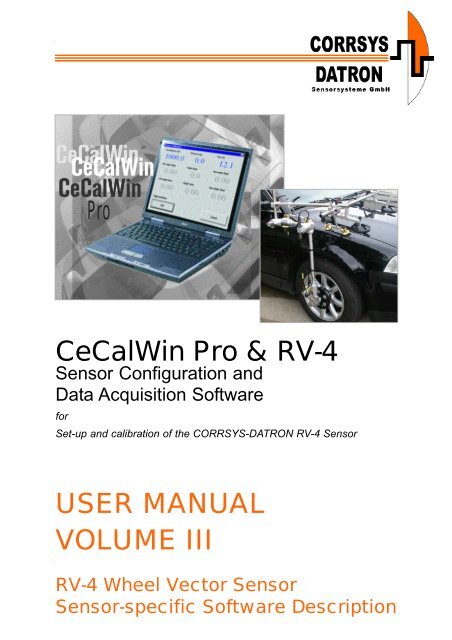
<strong>CeCalWin</strong> <strong>Pro</strong> & <strong>RV</strong>-4<br />
Sensor Configuration and<br />
Data Acquisition Software<br />
for<br />
Set-up and calibration of the CORRSYS-DATRON <strong>RV</strong>-4 Sensor<br />
<strong>USER</strong> <strong>MANUAL</strong><br />
<strong>VOLUME</strong> <strong>III</strong><br />
<strong>RV</strong>-4 Wheel Vector Sensor<br />
Sensor-specific Software Description
User Manual<br />
<strong>CeCalWin</strong> <strong>Pro</strong> with <strong>RV</strong>-4<br />
Note:<br />
For a general description of the <strong>CeCalWin</strong> <strong>Pro</strong> Software refer<br />
to the separate user manual Volume II.<br />
For the hardware description of the <strong>RV</strong>-4 Sensor refer to the<br />
separate user manual Volume I.<br />
© 2008 CORRSYS-DATRON Sensorsysteme GmbH <strong>RV</strong>4-CCW<strong>Pro</strong>_m-816-p3-e-rev001 11/08 2
User Manual<br />
<strong>CeCalWin</strong> <strong>Pro</strong> with <strong>RV</strong>-4<br />
<strong>VOLUME</strong> <strong>III</strong> - <strong>RV</strong>-4 Sensor specific<br />
Software Description<br />
Table of Contents<br />
General Information . . . . . . . . . . . . . . . . . . . . . . . . . . . . . . . . . . . . . . . . . . . .4<br />
Safety Instructions . . . . . . . . . . . . . . . . . . . . . . . . . . . . . . . . . . . . . . . . . . . . .5<br />
1. <strong>Pro</strong>ject Window Settings for the <strong>RV</strong>-4 Sensor . . . . . . . . . . . . . . . . .6<br />
1.1 Measurement Display . . . . . . . . . . . . . . . . . . . . . . . . . . . . . . . . . . . . . .6<br />
1.2 Input/Output Display . . . . . . . . . . . . . . . . . . . . . . . . . . . . . . . . . . . . . . .7<br />
1.3 Sensor Configuration . . . . . . . . . . . . . . . . . . . . . . . . . . . . . . . . . . . . . .8<br />
1.4 Digital Channels . . . . . . . . . . . . . . . . . . . . . . . . . . . . . . . . . . . . . . . . . .9<br />
1.5 Analog Channels . . . . . . . . . . . . . . . . . . . . . . . . . . . . . . . . . . . . . . . .10<br />
1.6 Filter . . . . . . . . . . . . . . . . . . . . . . . . . . . . . . . . . . . . . . . . . . . . . . . . .12<br />
1.7 CAN Bus . . . . . . . . . . . . . . . . . . . . . . . . . . . . . . . . . . . . . . . . . . . . . .13<br />
2. CAN-Bus <strong>Pro</strong>tocol . . . . . . . . . . . . . . . . . . . . . . . . . . . . . . . . . . . . . . . . .15<br />
2.1 Definition of the Frames . . . . . . . . . . . . . . . . . . . . . . . . . . . . . . . . . . .16<br />
3.1.1 Definition of the Intel Format . . . . . . . . . . . . . . . . . . . . . . . . . . .16<br />
3.1.2 Definition of the Motorola Format . . . . . . . . . . . . . . . . . . . . . . . .17<br />
2.2 Troubleshooting CAN-Bus . . . . . . . . . . . . . . . . . . . . . . . . . . . . . . . . .19<br />
3. Creation of CAN Database Files (CanDB) . . . . . . . . . . . . . . . . . . .20<br />
4. Firmware Update . . . . . . . . . . . . . . . . . . . . . . . . . . . . . . . . . . . . . . . . .21<br />
4.1 Performing the Firmware Update . . . . . . . . . . . . . . . . . . . . . . . . . . . .21<br />
4.2 <strong>Pro</strong>blems during the Firmware Update . . . . . . . . . . . . . . . . . . . . . . . .23<br />
© 2008 CORRSYS-DATRON Sensorsysteme GmbH <strong>RV</strong>4-CCW<strong>Pro</strong>_m-816-p3-e-rev001 11/08 3
User Manual<br />
General Information<br />
<strong>CeCalWin</strong> <strong>Pro</strong> with <strong>RV</strong>-4<br />
Legal Notice<br />
Information furnished is believed to be accurate and reliable. However, CORRSYS-DATRON assumes<br />
no responsibility for the consequences of use of such information nor for any infringement of patents<br />
or other rights of third parties which may result from its use. No license is granted by implication or<br />
otherwise under any patent or patent rights of CORRSYS-DATRON. Specifications mentioned in this<br />
publication are subject to change without notice and do not represent a commitment on the part of<br />
CORRSYS-DATRON. This publication supersedes and replaces all information previously supplied.<br />
All brand names are trademarks of their respective holders.<br />
Copyright Notice<br />
©Copyright 2008, CORRSYS-DATRON<br />
Revision<br />
<strong>RV</strong>4-CCW<strong>Pro</strong>_m-816-p3-e-rev001 11/08<br />
Contact<br />
International Headquarters:<br />
CORRSYS-DATRON Sensorsysteme GmbH<br />
Charlotte-Bamberg-Str. 12<br />
35578 Wetzlar / Germany<br />
Phone ++49 (6441) 9282-0<br />
Hotline ++49 (6441) 9282-82<br />
Fax ++49 (6441) 9282-17<br />
E-mail sales@corrsys-datron.com<br />
URL www.corrsys-datron.com<br />
North American Headquarters:<br />
CORRSYS-DATRON Sensorsystems, Inc.<br />
40000 Grand River, Suite 503<br />
Novi, MI 48375 / USA<br />
Phone ++1 (248) 615-2035<br />
Toll-free++1 (800) 832-0732<br />
Fax ++1 (248) 615-2184<br />
E-mail USA-sales@corrsys-datron.com<br />
URL www.corrsys-datron.com<br />
China Headquarters:<br />
CORRSYS-DATRON Sensorsysteme GmbH, China Office<br />
Room 708, JinTianDi International Mansion,<br />
No. 998 RenMin Road, Shanghai (200021), P.R.China<br />
Tel.: ++86-21-63114144<br />
Fax: ++86-21-63114154<br />
E-mail: Xiaoying.Li@corrsys-datron.com.cn<br />
URL: www.corrsys-datron.com.cn<br />
© 2008 CORRSYS-DATRON Sensorsysteme GmbH <strong>RV</strong>4-CCW<strong>Pro</strong>_m-816-p3-e-rev001 11/08 4
User Manual<br />
<strong>CeCalWin</strong> <strong>Pro</strong> with <strong>RV</strong>-4<br />
Safety Instructions<br />
Please read the following instructions carefully before installing or using<br />
<strong>CeCalWin</strong> <strong>Pro</strong> Software<br />
CORRSYS-DATRON is not responsible for damage that may occur if hardware and/or software is used<br />
in any way other than that for which it is intended.<br />
To assure safe and proper operation, all supplied equipment, components and/or accessories must be<br />
carefully transported and stored, as well as professionally installed and operated. Careful maintenance<br />
and usage in full accordance with operating instructions is imperative.<br />
CORRSYS-DATRON hardware and/or software should be installed and operated only by qualified<br />
persons who are familiar with devices of this type.<br />
Local regulations may not permit the operation of motor vehicles on public highways while the equipment<br />
is mounted on the exterior of the vehicle.<br />
• Use hardware and/or software only for intended applications. Improper application is not advised.<br />
• Do not modify or change equipment or its accessories in any way.<br />
• Improper use or mounting of the equipment may affect the safety of the vehicle and/or occupants.<br />
• The equipment must not be mounted and/or operated in any way that may compromise vehicle or<br />
and/or occupant safety.<br />
• Equipment must be mounted firmly and securely.<br />
• Use only original equipment, components and/or accessories included in the scope of delivery.<br />
• Do not mount equipment, components and/or accessories near heat sources (e.g. exhaust).<br />
• Do not use defective or damaged equipment, components and/or accessories.<br />
• Always note correct pin assignments and operating voltages when connecting equipment to<br />
power supplies, data acquisition/evaluation systems, and/or any other applicable system or<br />
component. Equipment may be damaged if not properly connected and/or operated.<br />
• CORRSYS-DATRON recommends using cables supplied within the scope of delivery. If it is necessary to<br />
make cables, always note correct pin assignments (see the pin assignments in the supplied<br />
sensor user manual).<br />
Damage to the device caused by cables other than those supplied by CORRSYS-<br />
DATRON is not covered under the product warranty.<br />
• For additional information, please call the CORRSYS-DATRON Hotline: ++49 (6441) 9282-82<br />
or email: hotline@corrsys-datron.com.<br />
© 2008 CORRSYS-DATRON Sensorsysteme GmbH <strong>RV</strong>4-CCW<strong>Pro</strong>_m-816-p3-e-rev001 11/08 5
User Manual<br />
<strong>CeCalWin</strong> <strong>Pro</strong> with <strong>RV</strong>-4<br />
1. <strong>Pro</strong>ject Window Settings for the <strong>RV</strong>-4 Sensor<br />
Within the <strong>Pro</strong>ject Window, either six or seven tabbed sections will be displayed: Measurement Display,<br />
Input/Output Display, Sensor Configuration, Digital Channels*, Analog Channels, Filter and CAN-Bus.<br />
Options for systemconfiguration, operation and data display are explained in the following pages.<br />
* NOTE: Digital Channels tab available only when an optional Wheel Pulse Transducer is activated<br />
1.1 Measurement Display<br />
The Measurement Display tab shows measurement values from the <strong>RV</strong>-4 Sensor(s), and activated Wheel<br />
Pulse Transducer(s), in real time.<br />
NOTES:<br />
Velocity and Distance values are available only when a Wheel Pulse Transducer is activated.<br />
Sensor 2 values are available only when a second <strong>RV</strong>-4 Sensor is activated.<br />
Sensor 1<br />
Values acquired from the <strong>RV</strong>-4 Sensor:<br />
X (mm): X-axis value, in millimeters<br />
Y (mm): Y-axis value, in millimeters<br />
Z (mm): Z-axis value, in millimeters<br />
Camber (°): camber angle value, in degrees<br />
Steer (°): steering angle value, in degrees<br />
Values acquired from the Wheel Pulse Transducer: (available only if activated)<br />
Velocity: velocity value, in kph or mph (user-selectable)<br />
Distance: distance value, in kilometers of miles (user-selectable)<br />
Sensor 2 (available only if activated)<br />
All value displays are the same as Sensor 1.<br />
© 2008 CORRSYS-DATRON Sensorsysteme GmbH <strong>RV</strong>4-CCW<strong>Pro</strong>_m-816-p3-e-rev001 11/08 6
User Manual<br />
<strong>CeCalWin</strong> <strong>Pro</strong> with <strong>RV</strong>-4<br />
Input/Output Display<br />
After mounting the <strong>RV</strong>-4, it is typical that the angular transducers in the sensor will not be positioned at<br />
their respective mechanical zero points. The Input/Output Display tab shows mechanical offset values for<br />
each of the angular transducers in the connected <strong>RV</strong>-4 Sensor(s), and enables the values for each transducer<br />
to be set as the zero-point from which dynamic measurement values will be determined.<br />
NOTE:<br />
Sensor 2 values are available only when a second <strong>RV</strong>-4 Sensor is activated.<br />
Sensor 1<br />
Digital Input<br />
a1 (1): angle 1 input value, in degrees<br />
a2 (2): angle 2 input value, in degrees<br />
a3 (3): angle 3 input value, in degrees<br />
a4 (4): angle 4 input value, in degrees<br />
a5 (5): angle 5 input value, in degrees<br />
Analog Output<br />
X (1): X-axis value, output as voltage<br />
Y (2): Y-axis value, output as voltage<br />
Z (3): Z-axis value, output as voltage<br />
Camber (4): camber angle value, output as voltage<br />
Steer (5): steering angle value, output as voltage<br />
Mechanical Offset<br />
Click on the Zero button to set all <strong>RV</strong>-4 Sensor mechanical offset values as a zero points.<br />
Sensor 2 (available only if activated*)<br />
All value displays are the same as Sensor 1.<br />
© 2008 CORRSYS-DATRON Sensorsysteme GmbH <strong>RV</strong>4-CCW<strong>Pro</strong>_m-816-p3-e-rev001 11/08 7
User Manual<br />
<strong>CeCalWin</strong> <strong>Pro</strong> with <strong>RV</strong>-4<br />
Sensor Configuration<br />
The Sensor Configuration tab enables sensor parameterization.<br />
NOTES:<br />
Wheel Pulse Transducer values are available only when a Wheel Pulse Transducer is activated.<br />
Sensor 2 values are available only when a second <strong>RV</strong>-4 Sensor is activated.<br />
Sensor 1<br />
L2: not user-selectable<br />
L1: not user-selectable<br />
S2: not user-selectable<br />
S1: enter the distance from the center of the tire’s width to the<br />
center of the retainer clamp bolt on the <strong>RV</strong>-4. The value (mm)<br />
can be entered manually, or selected with the up/down arrows.<br />
NOTE: This value must be entered to ensure proper calculation<br />
of steering angle.<br />
Tire Diameter:<br />
(required only if Wheel Pulse Transducer is activated)<br />
enter the diameter of the tire. The value (in millimeters) can be<br />
entered manually, or selected with the up/down arrows.<br />
Sensor Position: select left or right, corresponding to the<br />
side of the vehicle on which the sensor is mounted.<br />
Retainer clamp bolt<br />
Wheel Pulse Transducer (available only if Wheel Pulse Transducer is activated*)<br />
Calibration factor: user-selectable, values can be entered manually, or selected with the<br />
up/down arrows (default = 1.0000) or by calibration drive.<br />
Resolution: user-selectable (default = 1,000 pulses/rotation).<br />
Other values can be entered manually, or selected with the up/down arrows.<br />
Sensor 2 (available only if second <strong>RV</strong>-4 Sensor is activated)<br />
Select the Sensor 2 checkbox to activate the Sensor 2 interface.<br />
See Sensor 1, above, for setting instructions.<br />
© 2008 CORRSYS-DATRON Sensorsysteme GmbH <strong>RV</strong>4-CCW<strong>Pro</strong>_m-816-p3-e-rev001 11/08 8
User Manual<br />
<strong>CeCalWin</strong> <strong>Pro</strong> with <strong>RV</strong>-4<br />
Digital Channels<br />
The Digital Channels tab enables adjustment of digital signal output resolution for activated Wheel<br />
Pulse Transducer(s).<br />
*<br />
NOTES:<br />
Digital Channels tab is available only when the optional Wheel Pulse Transducer is activated.<br />
Sensor 2 is available only when a second <strong>RV</strong>-4 Sensor and Wheel Pulse Transducer are activated.<br />
Sensor 1<br />
Digital Channel 1<br />
Resolution: user-selectable (default = 460 P/m).<br />
Other values can be entered manually, or selected with the up/down arrows.<br />
Sensor 2 (available only if second <strong>RV</strong>-4 Sensor and Wheel Pulse Transducer are activated)<br />
See Sensor 1, above, for setting instructions.<br />
© 2008 CORRSYS-DATRON Sensorsysteme GmbH <strong>RV</strong>4-CCW<strong>Pro</strong>_m-816-p3-e-rev001 11/08 9
User Manual<br />
<strong>CeCalWin</strong> <strong>Pro</strong> with <strong>RV</strong>-4<br />
Analog Channels<br />
The Analog Channels tab enables adjustment of analog signal output settings for activated <strong>RV</strong>-4 Sensors.<br />
NOTE:<br />
Sensor 2 values are available only when a second <strong>RV</strong>-4 Sensor is activated.<br />
Sensor 1<br />
Analog Channel 1 data source is the X-axis value<br />
Resolution: user-selectable (default = 60 mV/mm).<br />
Other values can be entered manually, or selected with the up/down arrows.<br />
Offset: user-selectable (default = 0 mV).<br />
Other values can be entered manually, or selected with the up/down arrows.<br />
Analog Channel 2 data source is the Y-axis value<br />
Resolution: user-selectable (default = 60 mV/mm).<br />
Other values can be entered manually, or selected with the up/down arrows.<br />
Offset: user-selectable (default = 0 mV).<br />
Other values can be entered manually, or selected with the up/down arrows.<br />
Analog Channel 3 data source is the Z-axis value<br />
Resolution: user-selectable (default = 60 mV/mm).<br />
Other values can be entered manually, or selected with the up/down arrows.<br />
Offset: user-selectable (default = 0 mV).<br />
Other values can be entered manually, or selected with the up/down arrows.<br />
Analog Channels information continues on next page...<br />
© 2008 CORRSYS-DATRON Sensorsysteme GmbH <strong>RV</strong>4-CCW<strong>Pro</strong>_m-816-p3-e-rev001 11/08 10
User Manual<br />
<strong>CeCalWin</strong> <strong>Pro</strong> with <strong>RV</strong>-4<br />
Analog Channels, continued<br />
NOTE<br />
Sensor 2 values are available only when a second <strong>RV</strong>-4 Sensor is activated.<br />
Sensor 1<br />
Analog Channel 4 data source is the Camber Angle value<br />
Resolution: user-selectable (default = 1,000 mV/degree).<br />
Other values can be entered manually, or selected with the up/down arrows.<br />
Offset: user-selectable (default = 0 mV).<br />
Other values can be entered manually, or selected with the up/down arrows.<br />
Analog Channel 5 data source is the Steering Angle value<br />
Resolution: user-selectable (default = 200 mV/degree).<br />
Other values can be entered manually, or selected with the up/down arrows.<br />
Offset: user-selectable (default = 0 mV).<br />
Other values can be entered manually, or selected with the up/down arrows.<br />
Sensor 2 (available only if second <strong>RV</strong>-4 Sensor is activated*)<br />
See Sensor 1, above and on previous page, for setting instructions.<br />
© 2008 CORRSYS-DATRON Sensorsysteme GmbH <strong>RV</strong>4-CCW<strong>Pro</strong>_m-816-p3-e-rev001 11/08 11
User Manual<br />
<strong>CeCalWin</strong> <strong>Pro</strong> with <strong>RV</strong>-4<br />
Filter<br />
The Filter tab enables adjustment of the filter-time setting for the <strong>RV</strong>-4 Sensor.<br />
Filter Mode<br />
Select the checkbox to activate access to the filter-time setting for the <strong>RV</strong>-4 Sensor.<br />
Average Time: user-selectable (default value = 2 x 8 ms = 16 ms).<br />
Other values can be entered manually, or selected with the up/down arrows.<br />
© 2008 CORRSYS-DATRON Sensorsysteme GmbH <strong>RV</strong>4-CCW<strong>Pro</strong>_m-816-p3-e-rev001 11/08 12
User Manual<br />
<strong>CeCalWin</strong> <strong>Pro</strong> with <strong>RV</strong>-4<br />
CAN-Bus<br />
The CAN-Bus tab enables adjustment of the CAN-Bus settings.<br />
For additional CAN information, see Chapter 3, CAN <strong>Pro</strong>tocol, page 15ff.<br />
NOTES:<br />
Sensor 2 values are available only when a second <strong>RV</strong>-4 Sensor is activated.<br />
Optional values are available only when a Wheel Pulse Transducer is activated.<br />
Baud Rate (default = 1 MBaud)<br />
Use the pull-down menu to select either 1 MBaud, 500 kBaud, 250 kBaud or125 kBaud.<br />
Data Format (default = Intel)<br />
Use the pull-down menu to select either Intel or Motorola.<br />
Can Terminating Resistor (default = selected)<br />
Click on the checkbox to select or de-select the CAN Terminating Resistor option.<br />
Sensor 1<br />
ID Data Frame 1 (default setting = XTD)<br />
Select the desired Sensor Message Identifier mode: STD (standard, 11-bit) or XTD (extended, 29-bit).<br />
(Default value, STD = 7FA)<br />
(Default value, XTD = 1FFFFFFA)<br />
ID Data Frame 2 (default setting = XTD)<br />
Select the desired Sensor Message Identifier mode: STD (standard, 11-bit) or XTD (extended, 29-bit).<br />
(Default value, STD = 7FB)<br />
(Default value, XTD = 1FFFFFFB)<br />
Sensor 2 (available only if second <strong>RV</strong>-4 Sensor is activated)<br />
See Sensor 1, above, for setting instructions.<br />
CAN-Bus information continues on next page...<br />
© 2008 CORRSYS-DATRON Sensorsysteme GmbH <strong>RV</strong>4-CCW<strong>Pro</strong>_m-816-p3-e-rev001 11/08 13
User Manual<br />
<strong>CeCalWin</strong> <strong>Pro</strong> with <strong>RV</strong>-4<br />
CAN-Bus, continued<br />
NOTES:<br />
Sensor 2 values are available only when a second <strong>RV</strong>-4 Sensor is activated.<br />
Optional values are available only when a Wheel Pulse Transducer is activated.<br />
Optional (available only if Wheel Pulse Transducer is activated)<br />
Select the checkbox to activate ID Data Frame 3 settings.<br />
ID Data Frame 3 (default setting = XTD)<br />
Select the desired Sensor Message Identifier mode: STD (standard, 11-bit) or XTD (extended, 29-bit).<br />
(default value, STD = 7FE) (default value, XTD = 1FFFFFE)<br />
Continuous Send Mode (default setting = selected)<br />
Sets sensor to send CAN messages continuously and cyclically. (default = 8ms)<br />
Cycle times between 8ms and 1024ms (in 8ms steps) can be selected.<br />
Send Interval: (default setting = 1)<br />
Other values can be entered manually, or selected with the up/down arrows.<br />
Trigger Frame Mode (default setting = not selected)<br />
When selected, sets sensor to respond to CAN trigger frames from a master controller for<br />
synchronization.<br />
(default setting = XTD) (Default value, STD = 700 hex) (Default value, XTD = 10000000 hex)<br />
Remote Frame Mode (default setting = not selected)<br />
Sets the sensor to responds to a remote -frame request from a master controller. The sensor sends<br />
one Data Frame (response to the remote frame request) followed by the rest of Data Frames and, if<br />
selected, the optional Data Frame 3.<br />
© 2008 CORRSYS-DATRON Sensorsysteme GmbH <strong>RV</strong>4-CCW<strong>Pro</strong>_m-816-p3-e-rev001 11/08 14
User Manual<br />
<strong>CeCalWin</strong> <strong>Pro</strong> with <strong>RV</strong>-4<br />
2. Data <strong>Pro</strong>tocol CAN-Bus<br />
<strong>RV</strong>-x Sensors Version 1.1<br />
(Valid from Sensor Software Version 030-01-01-00)<br />
25.04.2006<br />
There are 3 modes of data transmission on the CAN bus. The transmission mode can be selected using<br />
<strong>CeCalWin</strong> <strong>Pro</strong>; combinations of modes are not possible. The CAN messages sent by the sensors for all<br />
three modes consist of one or more Frames (a Frame is defined in the CAN-bus specifications).<br />
The Sensor sends two Data_Frames. The frame format is the same for each send mode. It is possible<br />
to choose between Intel data format or Motorola data format.<br />
If a second sensor is connected to the electronics, its data frames will be sent additionally.<br />
It is possible to append one optional Data_Frame for <strong>RV</strong>-4 Sensors.<br />
Continuous-send mode (CONT):<br />
The messages are sent continuously and cyclically with a period set in <strong>CeCalWin</strong> <strong>Pro</strong> (by default 8ms).<br />
Cycle times between 8ms and 1024ms (in 8ms steps) can be selected.<br />
Remote Frame mode (REM):<br />
The sensor responds to a remote-frame request from a master controller. The sensor sends one<br />
Data_Frame (response to the remote frame request) followed by the second Data_Frame.<br />
Trigger Frame mode (TRG):<br />
The sensor responds to a trigger frame from a master controller (for synchronization).<br />
The trigger frame ID must be entered in the sensor using <strong>CeCalWin</strong> <strong>Pro</strong>.<br />
© 2008 CORRSYS-DATRON Sensorsysteme GmbH <strong>RV</strong>4-CCW<strong>Pro</strong>_m-816-p3-e-rev001 11/08 15
User Manual<br />
<strong>CeCalWin</strong> <strong>Pro</strong> with <strong>RV</strong>-4<br />
The Identifier numbers of all Data_Frames can be set separately in <strong>CeCalWin</strong> <strong>Pro</strong>. Baud rate and data<br />
format are selectable with <strong>CeCalWin</strong> <strong>Pro</strong> as well.<br />
CAN-bus type<br />
Baud rate<br />
Data format<br />
: CAN V2.0B<br />
: 1MBaud (default), 500kBaud, 250kBaud, 125kBaud<br />
: Intel (default), Motorola backward<br />
2.1 Definitions of the Frames<br />
The following definitions indicate how the data bytes within a CAN message frame are allocated in<br />
order to decipher the transmitted data.<br />
2.1.1 Definitions for Intel format:<br />
Data_Frame 1 (Sensor 1): Data_Frame 1 (Sensor 2):<br />
Format: 8 Data bytes<br />
Format: 8 Data bytes<br />
Default ID (Standard): 0x7FA<br />
Default ID (Standard): 0x7FC<br />
Default ID (Extended): 0x1FFFFFFA<br />
Default ID (Extended): 0x1FFFFFFC<br />
Data byte Description Unit Data type<br />
0 Timestamp (Bit 0...7)<br />
1 Timestamp (Bit 8...15)<br />
2 Coordinate X (Bit 0...7)<br />
3 Coordinate X (Bit 8...15)<br />
4 Coordinate Y (Bit 0...7)<br />
5 Coordinate Y (Bit 8...15)<br />
6 Coordinate Z (Bit 0...7)<br />
7 Coordinate Z (Bit 8...15)<br />
4 ms unsigned<br />
10 -2 mm signed<br />
10 -2 mm signed<br />
10 -2 mm signed<br />
Data_Frame 2 (Sensor 1): Data_Frame 2 (Sensor 2):<br />
Format: 8 Data bytes<br />
Format: 8 Data bytes<br />
Default ID (Standard): 0x7FB<br />
Default ID (Standard): 0x7FD<br />
Default ID (Extended): 0x1FFFFFFB<br />
Default ID (Extended): 0x1FFFFFFD<br />
Data byte Description Unit Data type<br />
0 Camber angle (Bit 0...7)<br />
1 Camber angle (Bit 8...15)<br />
2 Steer angle (Bit 0...7)<br />
3 Steer angle (Bit 8...15)<br />
4 Distance since sensor power on (Bit 0...7)<br />
5 Distance since sensor power on (Bit 8...15)<br />
6 Distance since sensor power on (Bit 16...23)<br />
7 Distance since sensor power on (Bit 24...31)<br />
10 -2 ° signed<br />
10 -2 ° signed<br />
mm<br />
unsigned<br />
© 2008 CORRSYS-DATRON Sensorsysteme GmbH <strong>RV</strong>4-CCW<strong>Pro</strong>_m-816-p3-e-rev001 11/08 16
User Manual<br />
<strong>CeCalWin</strong> <strong>Pro</strong> with <strong>RV</strong>-4<br />
Optional Data_Frame:<br />
Format: 2 Data bytes if one sensor is connected / 4 Data bytes if two sensors are connected<br />
Default ID (Standard): 0x7FE<br />
Default ID (Extended): 0x1FFFFFFE<br />
Data byte Description Unit Data type<br />
0 v (Bit 0...7) Sensor 1<br />
1 v (Bit 8...15) Sensor 1<br />
2 v (Bit 0...7) Sensor 2<br />
3 v (Bit 8...15) Sensor 2<br />
10 -2 m/s unsigned<br />
10 -2 m/s * unsigned<br />
* Note: Data byte 2 and 3 will be sent only when two sensors are connected to the <strong>RV</strong>-4 electronics.<br />
2.1.1 Definitions for Motorola format:<br />
Data_Frame 1 (Sensor 1): Data_Frame 1 (Sensor 2):<br />
Format: 8 Data bytes<br />
Format: 8 Data bytes<br />
Default ID (Standard): 0x7FA<br />
Default ID (Standard): 0x7FC<br />
Default ID (Extended): 0x1FFFFFFA<br />
Default ID (Extended): 0x1FFFFFFC<br />
Data byte Description Unit Data type<br />
0 Timestamp (Bit 8...15)<br />
1 Timestamp (Bit 0...7)<br />
2 Coordinate X (Bit 8...15)<br />
3 Coordinate X (Bit 0...7)<br />
4 Coordinate Y (Bit 8...15)<br />
5 Coordinate Y (Bit 0...7)<br />
6 Coordinate Z (Bit 8...15)<br />
7 Coordinate Z (Bit 0...7)<br />
4 ms unsigned<br />
10 -2 mm signed<br />
10 -2 mm signed<br />
10 -2 mm signed<br />
© 2008 CORRSYS-DATRON Sensorsysteme GmbH <strong>RV</strong>4-CCW<strong>Pro</strong>_m-816-p3-e-rev001 11/08 17
User Manual<br />
<strong>CeCalWin</strong> <strong>Pro</strong> with <strong>RV</strong>-4<br />
Data_Frame 2 (Sensor 1): Data_Frame 2 (Sensor 2):<br />
Format: 8 Data bytes<br />
Format: 8 Data bytes<br />
Default ID (Standard): 0x7FB<br />
Default ID (Standard): 0x7FD<br />
Default ID (Extended): 0x1FFFFFFB<br />
Default ID (Extended): 0x1FFFFFFD<br />
Data byte Description Unit Data type<br />
0 Camber angle (Bit 8...15)<br />
1 Camber angle (Bit 0...7)<br />
2 Steer angle (Bit 8...15)<br />
3 Steer angle (Bit 0...7)<br />
4 Distance since sensor power on (Bit 24...31)<br />
5 Distance since sensor power on (Bit 16...23)<br />
6 Distance since sensor power on (Bit 8...15)<br />
7 Distance since sensor power on (Bit 0...7)<br />
10 -2 ° signed<br />
10 -2 ° signed<br />
mm<br />
unsigned<br />
Optional Data_Frame:<br />
Format: 2 Data bytes if one sensor is connected / 4 Data bytes if two sensors are connected<br />
Default ID (Standard): 0x7FE<br />
Default ID (Extended): 0x1FFFFFFE<br />
Data byte Description Unit Data type<br />
0 v (Bit 8...15) Sensor 1<br />
1 v (Bit 0...7) Sensor 1<br />
2 * v (Bit 8...15) Sensor 2<br />
3 * v (Bit 0...7) Sensor 2<br />
10 -2 m/s unsigned<br />
10 -2 m/s unsigned<br />
* Note: Data byte 2 and 3 will be sent only when two sensors are connected to the <strong>RV</strong>-4 electronics.<br />
© 2008 CORRSYS-DATRON Sensorsysteme GmbH <strong>RV</strong>4-CCW<strong>Pro</strong>_m-816-p3-e-rev001 11/08 18
User Manual<br />
<strong>CeCalWin</strong> <strong>Pro</strong> with <strong>RV</strong>-4<br />
2.2 Troubleshooting CAN with the <strong>RV</strong>-4 Sensor<br />
Error: No messages are available on the CAN Bus<br />
Please be sure that:<br />
• The electronics unit is supplied with power.<br />
• The data acquisition system is connected to the electronics of the <strong>RV</strong>-4 Sensor.<br />
• Data acquisition system and sensor electronics have the same settings for baud rate, CAN Identifier<br />
and Identifier Types.<br />
• If you use a CANalyser or a data acquisition system with acceptance filter, be sure that the<br />
messages from the sensor are not blocked.<br />
<strong>Pro</strong>blem: Data received via the CAN bus appear to be incorrect<br />
Please be sure that:<br />
• the data acquisition system uses Intel data format for communication via CAN-bus<br />
• the data acquisition system and all sensor electronics use the same settings for the type of<br />
measured value (signed or unsigned, number of bits)<br />
• Incorrect data format is selected (Intel/Motorola)<br />
CORRSYS-DATRON recommends that the .dbc file option be used to avoid problems with false data<br />
types or bit lengths. Sensor-specific .dbc files are available for download at www.corrsys-datron.com, or<br />
may also be obtained by contacting the CORRSYS-DATRON application department directly.<br />
© 2008 CORRSYS-DATRON Sensorsysteme GmbH <strong>RV</strong>4-CCW<strong>Pro</strong>_m-816-p3-e-rev001 11/08 19
User Manual<br />
<strong>CeCalWin</strong> <strong>Pro</strong> with <strong>RV</strong>-4<br />
3. Creation of CAN Database Files (CanDB)<br />
From <strong>CeCalWin</strong><strong>Pro</strong> Version 1.9 on, it is possible to create CAN database files. These files provide an<br />
easy way to extract measured data from the CAN signals of CORRSYS-DATRON Sensors<br />
To start the generation of CAN database files, please select options>create CanDB<br />
After selecting this menu item, you will be prompted to choose a location for storing the CAN database<br />
file.<br />
Please select a suitable location and file name, and store the file by clicking the “Save” button.<br />
© 2008 CORRSYS-DATRON Sensorsysteme GmbH <strong>RV</strong>4-CCW<strong>Pro</strong>_m-816-p3-e-rev001 11/08 20
User Manual<br />
<strong>CeCalWin</strong> <strong>Pro</strong> with <strong>RV</strong>-4<br />
4. Firmware Update<br />
Due to the continuous development of our sensors, an update of the sensor firmware could be necessary.<br />
This chapter describes, how to perform this using <strong>CeCalWin</strong> <strong>Pro</strong>.<br />
This function is available from <strong>CeCalWin</strong> <strong>Pro</strong> Version 1.9 onwards.<br />
Note: Before you start the firmware update, please be sure that the data connection (USB or<br />
RS232) between the Computer and the Sensor as well as the power supply of the Computer and<br />
Sensor are correct.<br />
An interruption of sensor communication / power supply or a computer crash during the firmware<br />
update can result in an irreparable destruction of the sensor programming.<br />
4.1. Performing the Firmware Update:<br />
Step 1: Start the firmware update function<br />
To start the firmware update, please select Options>Loading new Firmware from the menu.<br />
© 2008 CORRSYS-DATRON Sensorsysteme GmbH <strong>RV</strong>4-CCW<strong>Pro</strong>_m-816-p3-e-rev001 11/08 21
User Manual<br />
<strong>CeCalWin</strong> <strong>Pro</strong> with <strong>RV</strong>-4<br />
Now, a message appears, prompting you to check data connection PC/Sensor and power supply.<br />
Please make sure that both, data connections and power supply, are correct and then confirm this message<br />
by clicking "OK".<br />
Step 2: Selection of firmware file<br />
Next, you will be prompted to select the firmware file, which you want to write into the sensor. For this<br />
purpose, please browse to the location on your hard disk, where the desired file is stored.<br />
Clicking on "Open" will confirm the firmware file and starts loading the new firmware.<br />
Note: From this moment on, the firmware update must not be interrupted!<br />
Step3: Loading the new firmware<br />
During the sensor programming, a status window appears that shows the actual progress of the firmware<br />
update.<br />
Temporarily, the progress bar may stop for a little moment. This is normal, caused by erasing of required<br />
memory space in the background.<br />
© 2008 CORRSYS-DATRON Sensorsysteme GmbH <strong>RV</strong>4-CCW<strong>Pro</strong>_m-816-p3-e-rev001 11/08 22
User Manual<br />
<strong>CeCalWin</strong> <strong>Pro</strong> with <strong>RV</strong>-4<br />
Step 4: Finishing the firmware update<br />
If the firmware update is finished successfully, the following message appears.<br />
After confirming this message by clicking the OK button, <strong>CeCalWin</strong><strong>Pro</strong> reads out the Sensor automatically<br />
and the firmare update is finished.<br />
4.2. <strong>Pro</strong>blems during the firmware update<br />
If an interruption of the communication connection between Computer and Sensor or a failure of the<br />
sensor power supply occurs during the firmware update, <strong>CeCalWin</strong><strong>Pro</strong> displayes the following error<br />
message.<br />
It is strongly recommended, to confirm this message with clicking the Retry button. The firmware update<br />
will be repeated automatically, depending on the BIOS, which is running in the Sensor (see procedure 1<br />
and procedure 2 below).<br />
Confirming this message by clicking the Cancel button, may result in irreparable damages of the sensor<br />
programming.<br />
<strong>Pro</strong>cedure 1 (newer BIOS Versions): In this case, the Retry of the firmware update begins with Step 3<br />
(please see chapter 4.1).<br />
<strong>Pro</strong>cedure 2 (older BIOS Versions): In this case, a hardware reset is necessary after confirming the<br />
message with “Retry”. This will be displayed with a message..<br />
After having confirmed this message with OK (Step 1), the power supply must be switched off and on<br />
(Step 2 ) within 5 seconds. Following, the firmware update will be continued with Step 3 (see chapter<br />
4.1).<br />
© 2008 CORRSYS-DATRON Sensorsysteme GmbH <strong>RV</strong>4-CCW<strong>Pro</strong>_m-816-p3-e-rev001 11/08 23