UDDEHOLM ORVAR 2 MICRODIZED
UDDEHOLM ORVAR 2 MICRODIZED
UDDEHOLM ORVAR 2 MICRODIZED

You also want an ePaper? Increase the reach of your titles
YUMPU automatically turns print PDFs into web optimized ePapers that Google loves.
<strong>UDDEHOLM</strong> <strong>ORVAR</strong> ® 2 <strong>MICRODIZED</strong>
© <strong>UDDEHOLM</strong>S AB<br />
No part of this publication may be reproduced or transmitted for commercial purposes<br />
without permission of the copyright holder.<br />
This information is based on our present state of knowledge and is intended to provide general<br />
notes on our products and their uses. It should not therefore be construed as a warranty of<br />
specific properties of the products described or a warranty for fitness for a particular purpose.<br />
Classified according to EU Directive 1999/45/EC<br />
For further information see our “Material Safety Data Sheets”.<br />
Edition 5, 05.2013<br />
The latest revised edition of this brochure is the English version,<br />
which is always published on our web site www.uddeholm.com<br />
2<br />
SS-EN ISO 9001<br />
SS-EN ISO 14001
<strong>UDDEHOLM</strong> <strong>ORVAR</strong> 2 <strong>MICRODIZED</strong><br />
General<br />
Uddeholm Orvar 2 Microdized is a chromiummolybdenum-vanadium-alloyed<br />
steel which is<br />
characterized by:<br />
•good resistance to abrasion at both low and<br />
high temperatures<br />
• high level of toughness and ductility<br />
• uniform and high level of machinability and<br />
polishability<br />
•good high-temperature strength and<br />
resistance to thermal fatigue<br />
•excellent through-hardening properties<br />
•very limited distortion during hardening.<br />
Typical C Si Mn Cr Mo V<br />
analysis % 0.39 1,0 0,4 5,3 1,3 0,9<br />
Standard<br />
specification<br />
Delivery<br />
condition<br />
Colour code<br />
AISI H13, W.-Nr. 1.2344, EN X40CrMoV5-1<br />
Soft annealed to approx. 185 HB<br />
Orange/violet<br />
Application<br />
Tools for extrusion<br />
Aluminium, Copper Stainless<br />
magnesium alloys steel<br />
Part alloys, HRC HRC HRC<br />
Dies 44–50 43–47 45–50<br />
Backers, dieholders,<br />
liners,<br />
dummy blocks,<br />
stems 41–50 40–48 40–48<br />
Austenitizing<br />
temperature 1020–1030°C 1040–1050°C<br />
(approx.) (1870–1885°F) (1900–1920°F)<br />
Plastic moulding applications<br />
Part Austenitizing temp. (approx.) HRC<br />
Injection moulds 1020–1030°C<br />
Compression/ (1870–1885°F) or<br />
transfer moulds 550–580°C (1020–1080°F) 48–50<br />
Other applications<br />
Application Austenitizing temp. (approx.) HRC<br />
Severe cold<br />
punching, 1020–1030°C (1870–1885°F)<br />
scrap shears Tempering 250°C (480°F) 50–52<br />
Hot shearing<br />
1020–1030°C (1870–1885°F)<br />
Tempering 250°C (480°F) 50–52<br />
or 575–600°C (1070–1110°F) 45–50<br />
Shrink rings<br />
(e.g. for 1020–1030°C (1870–1885°F)<br />
cemented Tempering 575–620°C<br />
carbide dies) (1070–1110°F) 45–50<br />
Wear- 1020–1030°C (1870–1885°F) In core<br />
resisting parts Tempering 575°C (1070°F) 50–52<br />
Nitriding<br />
On surface<br />
~1000 HV 1<br />
For applications requiring extreme levels of<br />
toughness and ductility e.g. die casting dies,<br />
forging dies, the premium grade H13-steel,<br />
Uddeholm Orvar Supreme, is recommended.<br />
3
<strong>UDDEHOLM</strong> <strong>ORVAR</strong> 2 <strong>MICRODIZED</strong><br />
Properties<br />
Physical data<br />
Unless otherwise is indicated all specimens<br />
were hardened 30 minutes at 1025°C (1875°F),<br />
quenched in air and tempered 2 + 2 h at 610°C<br />
(1130°F). The hardness were 45 ± 1 HRC.<br />
Temperature 20°C 400°C 600°C<br />
(68°F) (750°F) (1110°F)<br />
Density<br />
kg/m 3 7800 7700 7600<br />
lbs/in 3 0.281 0.277 0.274<br />
Modulus<br />
of elasticity<br />
N/mm 2 210 000 180 000 140 000<br />
psi 30.5 x 10 6 26.1 x 10 6 20.3 x 10 6<br />
Coefficient of<br />
thermal expansion<br />
per °C from 20°C – 12.6 x 10 -6 13.2 x 10 -6<br />
per °F from 68°F – 7.0 x 10 -6 7.3 x 10 -6<br />
Thermal<br />
conductivity<br />
W/m °C 25 29 30<br />
Btu in/(ft 2 h°F) 176 204 211<br />
Mechanical properties<br />
Approximate tensile strength at room temperature.<br />
Hardness 52 HRC 45 HRC<br />
Tensile strength Rm<br />
N/mm 2 1820 1420<br />
kp/mm 2 185 145<br />
psi 263 000 206 000<br />
Heat treatment<br />
Soft annealing<br />
Protect the steel and heat through to 850°C<br />
(1560°F). Then cool in the furnace at 10°C<br />
(20°F) per hour to 650°C (1200°F), then freely<br />
in air.<br />
stress relieving<br />
After rough machining the tool should be<br />
heated through to 650°C (1200°F), holding<br />
time 2 hours. Cool slowly to 500°C ( 930°F),<br />
then freely in air.<br />
Hardening<br />
Pre-heating temperature: 600–850°C (1110–<br />
1560°F), normally in two pre-heating steps.<br />
Austenitizing temperature: 1020–1050°C (1870–<br />
1920°F), normally 1020–1030°C (1870–<br />
1885°F).<br />
Temperature Soaking* time Hardness before<br />
°C °F minutes tempering<br />
1025 1875 30 53±2 HRC<br />
1050 1920 15 54±2 HRC<br />
* Soaking time = time at hardening temperature after the<br />
tool is fully heated through<br />
Protect the part against decarburization and<br />
oxidation during hardening.<br />
Yield point Rp0.2<br />
N/mm 2 1520 1280<br />
kp/mm 2 155 130<br />
psi 220 000 185 000<br />
APPROXIMATE STRENGTH<br />
AT ELEVATED TEMPERATURES<br />
Longitudinal direction.<br />
psi Rm, Rp0.2<br />
1000x MPa<br />
290 2000<br />
261 1800<br />
232 1600<br />
203 1400<br />
174 1200<br />
145 1000<br />
116 800<br />
87 600<br />
58 400<br />
29 200<br />
Rp0.2<br />
Rm<br />
100 200 300 400 500 600 700 °C<br />
210 390 570 750 930 1110 1290 °F<br />
Testing temperature<br />
4
<strong>UDDEHOLM</strong> <strong>ORVAR</strong> 2 <strong>MICRODIZED</strong><br />
CCT GRAPH<br />
Austenitizing temperature 1020°C (1870°F). Holding time 30<br />
°F °C<br />
2000 1100<br />
1800<br />
1600<br />
1400<br />
1200<br />
1000<br />
800<br />
600<br />
400<br />
200<br />
1000<br />
900<br />
800<br />
700<br />
600<br />
Carbides<br />
Austenitizing temp. 1020°C (1870°F)<br />
Holding time 30 min.<br />
Pearlite<br />
500<br />
2<br />
400<br />
3<br />
300<br />
Ms<br />
Bainite<br />
4<br />
5<br />
200<br />
6<br />
Mf<br />
Martensite<br />
100<br />
7<br />
1 2 3 4 5 6 7 8 8<br />
1 10 100 1 000 10 000<br />
Seconds<br />
1 10 100 1 000Minutes<br />
1 10 Hours<br />
Hours<br />
Aircooling of of<br />
0,2 1,5<br />
10 90<br />
bars, Ø mm<br />
0.0079 0.059 0.394 3.54 Ø inch<br />
Ac<br />
1f<br />
= 950°C (1740°F)<br />
Ac<br />
1s<br />
= 860°C (1580°F)<br />
Cooling<br />
Curve<br />
No.<br />
1<br />
Hardness T 800–500<br />
HV 10 sec.<br />
654<br />
586<br />
586<br />
574<br />
560<br />
551<br />
517<br />
451<br />
1<br />
37<br />
160<br />
280<br />
560<br />
1390<br />
3220<br />
8360<br />
Quenching media<br />
• High speed gas/circulating atmosphere<br />
•Vacuum (high speed gas with sufficient<br />
positive pressure). An interrupted<br />
quench is recommended where<br />
distortion control and quench cracking are<br />
a concern<br />
• Martempering bath or fluidized bed at 450–<br />
550°C (840–1020°F), then cool in air<br />
• Martempering bath or fluidized bed at<br />
180–220°C (360–430°F) then cool in air<br />
•Warm oil<br />
Note 1: Temper the tool as soon as its temperature<br />
reaches 50–70°C (120–160°F).<br />
Note 2: In order to obtain the optimum<br />
properties for the tool, the cooling rate should<br />
be fast, but not at a level that gives excessive<br />
distortion or cracks.<br />
HARDNESS, GRAIN SIZE AND RETAINED<br />
AUSTENITE AS FUNCTIONS OF AUSTENI-<br />
TIZING TEMPERATURE<br />
Grain<br />
size<br />
ASTM<br />
10<br />
8<br />
6<br />
4<br />
60<br />
58<br />
56<br />
54<br />
52<br />
50<br />
48<br />
46<br />
44<br />
42<br />
Hardness<br />
HRC<br />
Grain size<br />
Hardness<br />
Retained austenite<br />
Retained austenite %<br />
40<br />
1000 1020 1040 1060°C<br />
1830 1870 1900 1940°F<br />
Austenitizing temperature<br />
6<br />
4<br />
2<br />
5
<strong>UDDEHOLM</strong> <strong>ORVAR</strong> 2 <strong>MICRODIZED</strong><br />
Tempering<br />
Choose the tempering temperature according<br />
to the hardness required by reference to the<br />
tempering graph. Temper minimum twice with<br />
intermediate cooling to room temperature.<br />
Lowest tempering temperature 250°C (480°F).<br />
Holding time at temperature minimum 2 h.<br />
To avoid “temper brittleness”, do not temper<br />
in the range 425–550°C (800–1020°F), see<br />
graph.<br />
DIMENSIONAL CHANGES DURING HARDENING<br />
Sample plate, 100 x 100 x 25 mm, 4” x 4” x 1”.<br />
Width Length Thickness<br />
% % %<br />
Oil hardened from min –0.08 –0.06 0.00<br />
1000°C (1870°F) max –0.15 –0.16 +0.30<br />
Air hardened from min –0.02 –0.05 ±0<br />
1020°C (1870°F) max +0.03 +0.02 +0.05<br />
Vac hardened from min +0.01 –0.02 +0.08<br />
1020°C (1870°F) max +0.02 –0.04 +0.12<br />
TEMPERING GRAPH<br />
Hardness, HRC<br />
60<br />
Austenitizing<br />
temperature<br />
1050°C (1920°F)<br />
55<br />
50<br />
45<br />
40<br />
35<br />
30<br />
1020°C<br />
(1870°F)<br />
1025°C<br />
(1875°)<br />
Retained austenite<br />
Retained austenite %<br />
6<br />
4<br />
2<br />
DIMENSIONAL CHANGES DURING TEMPERING<br />
Dimensional change %<br />
+0,12<br />
+0,08<br />
+0,04<br />
0<br />
-0,04<br />
-0,08<br />
-0,12<br />
100 200 300 400 500 600 700°C<br />
210 390 570 750 930 1110 1290°F<br />
Tempering temperature (1h + 1h)<br />
Note: The dimensional changes in hardening and<br />
tempering should be added.<br />
25<br />
Tempering within the range 425–550°C (800–<br />
1020°F) is not normally recommended due to<br />
the reduction in toughness properties.<br />
Hardness, HRC<br />
58<br />
54<br />
50<br />
46<br />
42<br />
38<br />
34<br />
30<br />
100 200 300 400 500 600 700°C<br />
210 390 570 750 930 1110 1290°F<br />
Tempering temperature (2h + 2h)<br />
Above tempering curves are obtained after heat treatment of<br />
samples with a size of 15 x 15 x 40 mm, cooling in forced air.<br />
Lower hardness can be expected after heat treatment of<br />
tools and dies due to factors like actual tool size and heat<br />
treatment parameters.<br />
EFFECT OF TIME AT TEMPERING TEMPERATURE<br />
500°C<br />
(930°F)<br />
550°C<br />
(1020°F)<br />
Austenitizing<br />
temperature<br />
1020°C (1870°F) 600°C<br />
(1110°F)<br />
1 1.5 2.5 4 6.5 10 15 25 40 65 100 400<br />
Total holding time at tempering temperature, hours<br />
Nitriding and nitrocarburizing<br />
Nitriding and nitrocarburizing result in a hard<br />
surface layer which is very resistant to wear<br />
and erosion. The nitrided layer is, however,<br />
brittle and may crack or spall when exposed<br />
to mechanical or thermal shock, the risk increasing<br />
with layer thickness. Before nitriding,<br />
the tool should be hardened and tem-pered at<br />
a temperature at least 25–50°C (45–90°F)<br />
above the nitriding temperature.<br />
Nitriding in ammonia gas at 510°C (950°F)<br />
or plasma nitriding in a 75% hydrogen/25%<br />
nitrogen mixture at 480°C (895°F) both result<br />
in a surface hardness of about 1100 HV 0.2 . In<br />
general, plasma nitriding is the preferred<br />
method because of better control over nitrogen<br />
potential; in particular, for-mation of the<br />
so-called white layer, which is not recommended<br />
for hot work service, can readily be<br />
avoided. However, careful gas nitriding can give<br />
perfectly acceptable results.<br />
Uddeholm Orvar 2 Microdized can also be<br />
nitrocarburized in either gas or salt bath.<br />
The surface hardness after nitrocarburizing is<br />
900–1000 HV 0.2 .<br />
6
<strong>UDDEHOLM</strong> <strong>ORVAR</strong> 2 <strong>MICRODIZED</strong><br />
DEPTH OF NITRIDING<br />
Process Time Depth<br />
Gas nitriding at 510°C 10 h 0.12 mm<br />
30 h 0.20 mm<br />
Plasma nitriding at 480°C 10 h 0.12 mm<br />
30 h 0.18 mm<br />
Nitrocarburizing<br />
– in gas at at 580°C 2,5 h 0.11 mm<br />
– in salt bath at 580°C 1 h 0.06 mm<br />
Nitriding to case depths >0.3 mm (0.012 inch)<br />
is not recommended for hot-work applications.<br />
Uddeholm Orvar 2 Microdized can be nitrided<br />
in the soft-annealed condition. The hardness<br />
and depth of case will, however, be reduced<br />
somewhat in this case.<br />
Machining<br />
recommendations<br />
The cutting data below are to be considered<br />
as guiding values, which must be adapted to<br />
existing local conditions. More information can<br />
be found in the Uddeholm publication “Cutting<br />
data recommendations”.<br />
Condition: Soft annealed to approx. 185 HB<br />
Turning<br />
Turning with Turning<br />
carbide<br />
with high<br />
speed steel<br />
Cutting data Rough Fine Fine<br />
parameters turning turning turning<br />
Cutting<br />
speed (v c ) 200–250 250–300 25–30<br />
m/min 200–250 250–300 25–30<br />
f.p.m. 656–820 820–984 82–98<br />
Feed (f)<br />
mm/r 0.2–0.4 0.05–0.2 0.05–0.3<br />
i.p.r. 0.008–0.016 0.002–0.008 0.002–0.01<br />
Depth of cut (a p<br />
)<br />
mm 2–4 0.5–2 0.5–3<br />
inch 0.08–0.16 0.02–0.08 0.02–0.12<br />
Carbide<br />
designation<br />
ISO P20–P30 P10 –<br />
US C6–C5 C7 –<br />
Coated<br />
carbide<br />
Coated<br />
carbide<br />
or cermet<br />
Drilling<br />
HIGH SPEED STEEL TWIST DRILL<br />
Drill diameter Cutting speed, v c Feed, f<br />
mm inch m/min f.p.m. mm/r i.p.r.<br />
– 5 –3/16 16–18* 52–59* 0.05–0.15 0.002–0.006<br />
5–10 3/16–3/8 16–18* 52–59* 0.15–0.20 0.006–0.008<br />
10–15 3/8–5/8 16–18* 52–59* 0.20–0.25 0.008–0.010<br />
15–20 5/8–3/4 16–18* 52–59* 0.25–0.35 0.010–0.014<br />
* For coated HSS drill v c = 28–30 m/min. (92–98 f.p.m.)<br />
CARBIDE DRILL<br />
Type of drill<br />
Cutting data Indexable Solid Carbide<br />
parameters insert carbide tip 1)<br />
Cutting<br />
speed (v c )<br />
m/min 220–240 130–160 80–110<br />
f.p.m. 720–785 425–525 260–360<br />
Feed (f)<br />
mm/r 0.03–0.12 2) 0.08–0.20 3) 0.15–0.25 4)<br />
i.p.r. 0.001–0.005 2) 0.003–0.008 3) 0.006–0.010 4)<br />
1)<br />
Drill with replaceable or brazed carbide tip<br />
2)<br />
Feed rate for drill diameter 20–40 mm (0.8”–1.6”)<br />
3)<br />
Feed rate for drill diameter 5–20 mm (0.2”–0.8”)<br />
4)<br />
Feed rate for drill diameter 10–20 mm (0.4”–0.8”)<br />
Milling<br />
FACE AND SQUARE SHOULDER MILLING<br />
Milling with carbide<br />
Cutting data<br />
parameters Rough milling Fine milling<br />
Cutting speed (v c )<br />
m/min 180–260 260–300<br />
f.p.m. 591–853 853–984<br />
Feed (f z )<br />
mm/tooth 0.2–0.4 0.1–0.2<br />
inch/tooth 0.008–0.016 0.004–0.008<br />
Depth of cut (a p )<br />
mm 2–5 –2<br />
inch 0.08–0.2 –0.08<br />
Carbide designation<br />
ISO P20–P40 P10–P20<br />
US C6–C5 C6–C7<br />
Coated carbide Coated carbide<br />
or cermet<br />
7
<strong>UDDEHOLM</strong> <strong>ORVAR</strong> 2 <strong>MICRODIZED</strong><br />
END MILLING<br />
Type of end mill<br />
Carbide<br />
Cutting data Solid indexable High<br />
parameters carbide insert speed steel<br />
Cutting<br />
speed (v c )<br />
m/min 160–200 170–230 35–40 1)<br />
f.p.m. 525–660 560–755 115–130 1)<br />
Feed (f z )<br />
mm/tooth 0.03–0.20 2) 0.08–0.20 2) 0.05–0.35 2)<br />
inch/tooth 0.001–0.008 2) 0.003–0.008 2) 0.002–0.014 2)<br />
Carbide<br />
designation<br />
ISO – P20, P30 –<br />
1)<br />
For coated HSS end mill v c = 55–60 m/min. (180–195 f.p.m.)<br />
2)<br />
Depending on radial depth of cut and cutter diameter<br />
Grinding<br />
A general grinding wheel recommendation is<br />
given below. More information can be found in<br />
the Uddeholm brochure “Grinding of Tool<br />
Steel” and can also be obtained from the<br />
grinding wheel manufacturer.<br />
Soft annealed Hardened<br />
Type of grinding condition condition<br />
Face grinding<br />
straight wheel A 46 HV A 46 HV<br />
Face grinding<br />
segments A 24 GV A 36 GV<br />
Cylindrical grinding A 46 LV A 60 KV<br />
Internal grinding A 46 JV A 60 IV<br />
Profile grinding A 100 KV A 120 KV<br />
Electrical-discharge<br />
machining<br />
If spark-erosion is performed in the hardened<br />
and tempered condition, the white re-cast<br />
layer should be removed mechanically e.g. by<br />
grinding or stoning. The tool should then be<br />
given an additional temper at approx. 25°C<br />
(50°F ) below the previous tempering temperature.<br />
Hard-chromium plating<br />
After plating, parts should be tempered at<br />
180°C (360°F) for 4 hours within 4 hours of<br />
plating to avoid the risk of hydrogen embrittlement.<br />
Welding<br />
Welding of tool steel can be performed with<br />
good results if proper precautions are taken<br />
regarding elevated temperature, joint preparation,<br />
choice of consumables and welding<br />
procedure.<br />
Welding method TIG MMA<br />
Working min. 325°C min. 325°C<br />
temperature (min. 620°F) (min. 620°F)<br />
Filler metal<br />
Cooling rate<br />
QRO 90 TIG-WELD QRO 90 WELD<br />
DIEVAR TIG-WELD UTP 673<br />
20–40°C/h (35–70°F/h) the first 2–3 h<br />
then freely in air.<br />
Hardness 48–53 HRC<br />
after welding 48–53 HRC 55–58 HRC (673)<br />
Heat treatment after welding:<br />
Hardened Temper at 10–20°C (20–35°F) below<br />
condition the original tempering temperature.<br />
Soft annealed Soft-anneal the material at 850°C<br />
condition (1560°F) in protected atmosphere.<br />
Then cool in the furnace at 10°C<br />
(20°F) per hour to 650°C (1200°F)<br />
then freely in air.<br />
More detailed information can be found in the<br />
Uddeholm brochure “Welding of Tool Steel”.<br />
Polishing<br />
Uddeholm Orvar 2 Microdized exhibits good<br />
polishability in the hardened and tempered<br />
condition. Polishing after grinding can be<br />
effected using aluminium oxide or diamond<br />
paste.<br />
Typical procedure:<br />
1. Rough grinding to 180–320 grain size using a<br />
wheel or stone.<br />
2. Fine grinding with abrasive paper or powder<br />
down to 400–800 grain size.<br />
3. Polish with diamond paste grade 15 (15µm<br />
grain size) using a polishing tool of soft<br />
wood or fibre.<br />
4. Polish with diamond paste 8–6–3 (8–6–3µm<br />
grain size) using a polishing tool of soft<br />
wood or fibre.<br />
5. When demands on surface finish are high,<br />
grade 1 (1µm grain size) diamond paste can<br />
be used for final polishing with a fibre<br />
polishing pad.<br />
8
<strong>UDDEHOLM</strong> <strong>ORVAR</strong> 2 <strong>MICRODIZED</strong><br />
Photo-etching<br />
Uddeholm Orvar 2 Microdized is particularly<br />
suitable for texturing by the photo-etching<br />
method. Its high level of homogeneity and low<br />
sulphur content ensures accurate and consistent<br />
pattern reproduction.<br />
Further information<br />
Please contact your local Uddeholm office for<br />
further information on the selection, heat<br />
treatment, application and availability of<br />
Uddeholm tool steel.<br />
9
<strong>UDDEHOLM</strong> <strong>ORVAR</strong> 2 <strong>MICRODIZED</strong><br />
ELECTRIC ARC<br />
FURNACE<br />
ESR-PLANT<br />
UPHILL CASTING<br />
HEAT<br />
TREATMENT<br />
ROLLING MILL<br />
FORGING<br />
MACHINING<br />
STOCK<br />
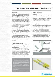
The ESR Tool Steel Process<br />
The starting material for our tool steel is carefully selected<br />
from high quality recyclable steel. Together with<br />
ferroalloys and slag formers, the recyclable steel is melted<br />
in an electric arc furnace. The molten steel is then tapped<br />
into a ladle.<br />
The de-slagging unit removes oxygen-rich slag and<br />
after the de-oxidation, alloying and heating of the steel<br />
bath are carried out in the ladle furnace. Vacuum degassing<br />
removes elements such as hydrogen, nitrogen and<br />
sulphur.<br />
ESR PLANT<br />
In uphill casting the prepared moulds are filled with a<br />
controlled flow of molten steel from the ladle.<br />
From this, the steel can go directly to our rolling mill<br />
or to the forging press, but also to our ESR furnace<br />
where our most sophisticated steel grades are melted<br />
once again in an electro slag remelting process. This is<br />
done by melting a consumable electrode immersed in an<br />
overheated slag bath. Controlled solidification in the steel<br />
bath results in an ingot of high homogeneity, thereby<br />
removing macro segregation. Melting under a protective<br />
atmosphere gives an even better steel cleanliness.<br />
HOT WORKING<br />
From the ESR plant, the steel goes to the rolling mill or<br />
to our forging press to be formed into round or flat bars.<br />
Prior to delivery all of the different bar materials are<br />
subjected to a heat treatment operation, either as soft<br />
annealing or hardening and tempering. These operations<br />
provide the steel with the right balance between hardness<br />
and toughness.<br />
MACHINING<br />
Before the material is finished and put into stock, we also<br />
rough machine the bar profiles to required size and exact<br />
tolerances. In the lathe machining of large dimensions, the<br />
steel bar rotates against a stationary cutting tool. In<br />
peeling of smaller dimensions, the cutting tools revolve<br />
around the bar.<br />
To safeguard our quality and guarantee the integrity of<br />
the tool steel we perform both surface- and ultrasonic<br />
inspections on all bars. We then remove the bar ends and<br />
any defects found during the inspection.<br />
10
Network of excellence<br />
<strong>UDDEHOLM</strong> is present on every continent. This ensures you<br />
high-quality Swedish tool steel and local support wherever you<br />
are. ASSAB is our exclusive sales channel, representing Uddeholm<br />
in the Asia Pacific area. Together we secure our position<br />
as the world’s leading supplier of tooling materials.<br />
www.assab.com<br />
www.uddeholm.com
<strong>UDDEHOLM</strong> 130501.150 / STROKIRK KNAPPEN 201305<br />
<strong>UDDEHOLM</strong> is the world’s leading supplier of tooling materials. This<br />
is a position we have reached by improving our customers’ everyday<br />
business. Long tradition combined with research and product development<br />
equips Uddeholm to solve any tooling problem that may arise.<br />
It is a challenging process, but the goal is clear – to be your number one<br />
partner and tool steel provider.<br />
Our presence on every continent guarantees you the same high quality<br />
wherever you are. ASSAB is our exclusive sales channel, representing<br />
Uddeholm in the Asia Pacific area. Together we secure our position as<br />
the world’s leading supplier of tooling materials. We act worldwide, so<br />
there is always an Uddeholm or ASSAB representative close at hand to<br />
give local advice and support. For us it is all a matter of trust – in longterm<br />
partnerships as well as in developing new products. Trust is<br />
something you earn, every day.<br />
For more information, please visit www.uddeholm.com, www.assab.com<br />
or your local website.