Installation Instructions - Custom Dynamics
Installation Instructions - Custom Dynamics
Installation Instructions - Custom Dynamics

You also want an ePaper? Increase the reach of your titles
YUMPU automatically turns print PDFs into web optimized ePapers that Google loves.
I N S TA L L AT I O N<br />
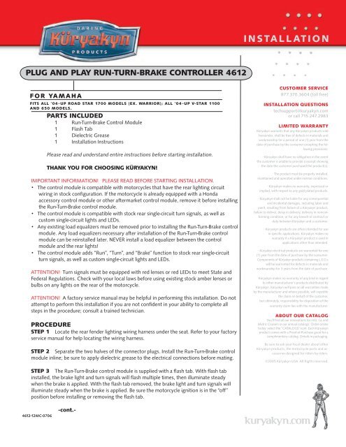
plug and play run-turn-brake controller 4612<br />
f o r ya m a h a<br />
Fits all ’04–up Road Star 1700 models (ex. Warrior); all ’04–up V-Star 1100<br />
and 650 models.<br />
Parts Included<br />
1 Run-Turn-Brake Control Module<br />
1 Flash Tab<br />
1 Dielectric Grease<br />
1 <strong>Installation</strong> <strong>Instructions</strong><br />
Please read and understand entire instructions before starting installation.<br />
Thank you for choosing Küryakyn!<br />
Important Information! Please read before starting installation.<br />
●• The control module is compatible with motorcycles that have the rear lighting circuit<br />
wiring in stock configuration. If the motorcycle is already equipped with a Honda<br />
accessory control module or other aftermarket control module, remove it before installing<br />
the Run-Turn-Brake control module.<br />
●• The control module is compatible with stock rear single-circuit turn signals, as well as<br />
custom single-circuit lights and LEDs.<br />
●• Any existing load equalizers must be removed prior to installing the Run-Turn-Brake control<br />
module. Any load equalizers necessary after installation of the Run-Turn-Brake control<br />
module can be reinstalled later. NEVER install a load equalizer between the control<br />
module and the rear lights!<br />
●• The control module adds “Run”, “Turn”, and “Brake” function to stock rear single-circuit<br />
turn signals, as well as custom single-circuit lights and LEDs.<br />
Attention! Turn signals must be equipped with red lenses or red LEDs to meet State and<br />
Federal Regulations. Check with your local laws before using existing stock amber lenses or<br />
bulbs on any lights on the rear of the motorcycle.<br />
Attention! A factory service manual may be helpful in performing this installation. Do not<br />
attempt to perform this installation if you are not confident in your ability to complete all<br />
steps in the procedure; consult a trained technician.<br />
Procedure<br />
STEP 1 Locate the rear fender lighting wiring harness under the seat. Refer to your factory<br />
service manual for help locating the wiring harness.<br />
STEP 2 Separate the two halves of the connector plugs. Install the Run-Turn-Brake control<br />
module inline; be sure to apply dielectric grease to the electrical connections before mating.<br />
CUSTOMER SERVICE<br />
877.370.3604 (toll free)<br />
INSTALLATION QUESTIONS<br />
techsupport@kuryakyn.com<br />
or call 715.247.2983<br />
LIMITED WARRANTY<br />
Küryakyn warrants that any Küryakyn products sold<br />
hereunder, shall be free of defects in materials and<br />
workmanship for a period of one (1) year from the<br />
date of purchase by the consumer excepting the following<br />
provisions:<br />
• Küryakyn shall have no obligation in the event<br />
the customer is unable to provide a receipt showing<br />
the date the customer purchased the product(s).<br />
• The product must be properly installed,<br />
maintained and operated under normal conditions.<br />
• Küryakyn makes no warranty, expressed or<br />
implied, with respect to any gold plated products.<br />
• Küryakyn shall not be liable for any consequential<br />
and incidental damages, including labor and<br />
paint, resulting from failure of a Küryakyn product,<br />
failure to deliver, delay in delivery, delivery in nonconforming<br />
condition, or for any breech of contract or<br />
duty between Küryakyn and a customer.<br />
• Küryakyn products are often intended for use<br />
in specific applications. Küryakyn makes no<br />
warranty if a Küryakyn product is used in<br />
applications other than intended.<br />
• Küryakyn electrical products are warranted for one<br />
(1) year from the date of purchase by the consumer.<br />
Components of Küryakyn products containing L.E.D.s<br />
will be warranted for defects in materials and<br />
workmanship for 3 years from the date of purchase.<br />
• Küryakyn makes no warranty of any kind in regard<br />
to other manufacturer’s products distributed by<br />
Küryakyn. Küryakyn will pass on all warranties made<br />
by the manufacturer and where possible, will expedite<br />
the claim on behalf of the customer,<br />
but ultimately, responsibility for disposition of the<br />
warranty claim lies with the manufacturer.<br />
ABOUT OUR CATALOG<br />
You’ll find all our innovations for H-D, GL and<br />
Metric Cruisers in our annual catalogs. Order online<br />
today–select the ”CATALOGS” icon. Each Küryakyn®<br />
product comes with a Proof-of-Purchase good for a<br />
complimentary catalog. Details in packaging.<br />
Be sure to ask your local dealer about other<br />
Küryakyn products, the motorcycle parts and accessories<br />
designed for riders by riders.<br />
©2005 Küryakyn USA ® All Rights reserved.<br />
STEP 3 The Run-Turn-Brake control module is supplied with a flash tab. With flash tab<br />
installed, the brake light and turn signals will flash multiple times, then illuminate steady<br />
when the brake is applied. With the flash tab removed, the brake light and turn signals will<br />
illuminate steady when the brake is applied. Be sure the motorcycle ignition is in the “off”<br />
position before installing or removing the flash tab.<br />
4612-12MC-0706<br />
-cont.-
STEP 4 Start the motorcycle and test the function of the Run-Turn-Brake control module:<br />
A) Verify the tail lamp and turn signals illuminate.<br />
B) Apply the brake; if the flash tab is installed, verify<br />
the brake light and turn signals flash multiple times<br />
before illuminating steady. If the flash tab is not<br />
installed, verify the brake light and turn signals<br />
illuminate steady while the brake is activated.<br />
C) Verify that when either of the turn signals are<br />
applied that they do not flash too rapidly or operate<br />
erratically. If this occurs, you will need to install a<br />
load equalizer. See the end of this document for the<br />
load equalizer installation procedure.<br />
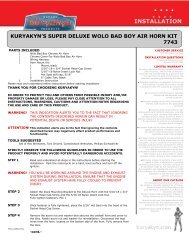
PIC.1<br />
load equalizer<br />
connections<br />
in-line<br />
connection<br />
STEP 5 Stow the Run-Turn-Brake control module<br />
under the seat. If you will not be installing the load<br />
equalizer, replace the seat. If you will be installing the<br />
load equalizer, leave the seat off and proceed to the<br />
next section.<br />
Installing the Load Equalizer<br />
in-line<br />
connection<br />
fl ash tab<br />
Attention! Any load equalizers must be installed upstream of the Run-Turn-Brake control module.<br />
NEVER install a load equalizer between the Run-Turn-Brake control module and the rear lights.<br />
STEP 6 The motorcycle must be “off” before installing the load equalizer. Locate the Run-Turn-Brake<br />
control module and plug the load equalizer into one of the empty 3-pin socket on the control module.<br />
STEP 7 Start the motorcycle and retest the light functions, refer to STEP 4. If the lights still flash too<br />
rapidly or operate erratically, you will need to install a second load equalizer (Küryakyn P/N 4810, sold<br />
separately).<br />
STEP 8 The load equalizers become warm during normal operation of the turn signals. Secure the load<br />
equalizer to the motorcycle frame; this will act as a heat sink and help cool the load equalizer. Keep the<br />
load equalizer away from any heat-sensitive components.<br />
Warning! Always install the load equalizer upstream of any existing<br />
aftermarket multifunction control modules. Do not install a load equalizer<br />
between a module and the turn signals as this will overload the module.<br />
Overloading will damage the module and create a fire hazard!<br />
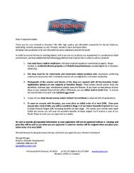
PIC.2<br />
Warning! Load equalizers generate heat when in use. Avoid using the<br />
turn signals for an extended period of time, otherwise the load equalizer<br />
will overheat. Never operate the four-way flashers unless you first remove<br />
the load equalizer. Overheating will damage the load equalizer, causing<br />
loss of turn signal operation and creates a fire hazard!<br />
Ride On!<br />
Page<br />
2<br />
p l u g a n d p l ay<br />
INSTALLATION