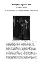
The Speed of Light: Historical Perspective and Experimental Findings
The Speed of Light: Historical Perspective and Experimental Findings
The Speed of Light: Historical Perspective and Experimental Findings

Create successful ePaper yourself
Turn your PDF publications into a flip-book with our unique Google optimized e-Paper software.
TRENT SCARBOROUGH AND BEN WILLIAMSON<br />
moved to the edge <strong>of</strong> the table so that an exact measurement<br />
could be taken for the distance from the mirror to the laser.<br />
Once the laser was turned on, the lens was moved in order to<br />
focus the reflected laser beam into the most precise dot onto the<br />
receiver. Different lengths are measured out on the floor ranging<br />
from approximately 1 m to 23 m. Once all <strong>of</strong> the equipment was<br />
set up, data collection could begin. <strong>The</strong> function generator is set<br />
to a square wave with a DC <strong>of</strong>fset <strong>and</strong> the frequency is set to<br />
2.683 x 10 6 Hertz (Hz). On the oscilloscope, channel 1 is set to<br />
1 volt per division (V/div), direct current, channel 2 is set to 1<br />
V/div, alternating current, <strong>and</strong> the trigger level was set to<br />
approximately 2.5 volts (V) <strong>and</strong> the base time set to 0.2<br />
microseconds per division (µs/div). <strong>The</strong> DC <strong>of</strong>fset <strong>and</strong> amplitude<br />
on the function generator is then tuned to maximize the sine<br />
wave signal on channel 2.<br />
Using a Vernier caliper, an initial distance between the<br />
square wave <strong>of</strong> channel 1 <strong>and</strong> the sine wave <strong>of</strong> channel 2 is<br />
found to be 0.25 cm. This initial distance reading took place with<br />
the mirror at a distance from the laser <strong>of</strong> 1.080 m. This initial<br />
reading would then become the baseline for all the following<br />
measurements to be based upon. <strong>The</strong> mirror is then moved<br />
back approximately 2 m <strong>and</strong> the distance between the square<br />
wave <strong>of</strong> channel 1 <strong>and</strong> the sine wave <strong>of</strong> channel 2 is re-measured.<br />
This procedure is repeated until the distance from the mirror<br />
<strong>and</strong> the laser reaches 23 m. <strong>The</strong> change in distance <strong>of</strong> the<br />
square wave to sine wave minus the initial distance <strong>of</strong> 0.25 cm<br />
(?t) is plotted against 2 times the laser to mirror distance minus<br />
the initial distance <strong>of</strong> 1.080 m (?d). In order to get our ?t measurements<br />
out <strong>of</strong> centimeters <strong>and</strong> into seconds we have to apply<br />
what we know about the set up <strong>of</strong> the equipment. Since we<br />
have the division setting on 0.2 µs/div, we measured that 1.00<br />
cm equals 5 divisions (div) on the oscilloscope. <strong>The</strong>refore 1 div<br />
is equal to 0.20 cm, <strong>and</strong> every cm is equal to 1 µs or 1000<br />
nanoseconds (ns). Using Micros<strong>of</strong>t Excel, a spreadsheet <strong>and</strong> a<br />
graph were created. By connecting the data points, a line is<br />
formed <strong>and</strong> the slope <strong>of</strong> the line found. Since ?t vs. ?v gives the<br />
slope <strong>of</strong> the line in units <strong>of</strong> m/s. We can deduce that the slope,<br />
2.956 x10 8 m/s, is the speed <strong>of</strong> light. Our measurement is only<br />
1.4% <strong>of</strong>f from the currently accepted value <strong>of</strong> 2.99792 x 10 8<br />
m/s.<br />
193