40Gbit/s Single Electrode Intensity Modulator
40Gbit/s Single Electrode Intensity Modulator
40Gbit/s Single Electrode Intensity Modulator

Create successful ePaper yourself
Turn your PDF publications into a flip-book with our unique Google optimized e-Paper software.
LN MODULATORS<br />
SUMITOMO OSAKA CEMENT CO.,LTD.<br />
LN MODULATORS<br />
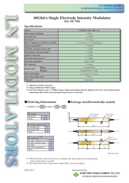
Specifications<br />
Model<br />
<strong>40Gbit</strong>/s <strong>Single</strong> <strong>Electrode</strong> <strong>Intensity</strong> <strong>Modulator</strong><br />
Operating wavelength<br />
Insertion loss<br />
DC Port Vπ<br />
Drive Voltage(Vπ) at RF Port @1GHz<br />
Optical bandwidth *1<br />
ON/OFF extinction ratio at DC<br />
Polarization extinction ratio *2<br />
Optical return loss<br />
Maximum input power *3<br />
<strong>Electrode</strong> impedance<br />
RF connector<br />
Optical fiber<br />
Fiber lead length<br />
Input<br />
Output<br />
Operating temperature<br />
Polarizer<br />
Ordering Information<br />
T.MZH1.5-40 X ADC Y Z<br />
X: Option<br />
With PD<br />
None<br />
PD<br />
Blank<br />
Y: Output Optical fiber<br />
*1<br />
0.9mmΦ PMF P<br />
0.9mmΦ SMF S<br />
Other<br />
O<br />
Z: Connector<br />
*1,2<br />
FC/SPC without key ring<br />
FC/SPC with key ring<br />
SC/SPC<br />
SC/APC(Angled PC)<br />
Other<br />
FN<br />
FK<br />
SC<br />
FA<br />
O<br />
(for OC768)<br />
150.25<br />
T . MZH1.5-40X-ADC-Y-Z<br />
1.55µm<br />
/=30dB<br />
/=20dB at input. Input polarization must be aligned to the slow axis of polarization<br />
maintaining fiber before the maximum input powser is inserted.<br />
Package size(Hermetically-sealed)<br />
11<br />
DC-Conector<br />
K. Female<br />
120<br />
30.7 60.2<br />
36 48 36<br />
*1: When Other O is selected in the above ordering code, please specify your requirements<br />
with as much detail as possible.<br />
*2: The Polarization state of input and/or output PMF is slow axis aligned.<br />
RF-Conector<br />
V. Female<br />
4-M2.52<br />
Mounting Hole<br />
[Dimension:mm]<br />
2002 JULY Manufactured by :<br />
SUMITOMO OSAKA CEMENT CO.,LTD.<br />
OPTOELECTRONICS BUSINESS DIVISION
LN MODULATORS<br />
SUMITOMO OSAKA CEMENT CO.,LTD.<br />
LN MODULATORS<br />
<strong>40Gbit</strong>/s <strong>Single</strong> <strong>Electrode</strong> <strong>Intensity</strong> <strong>Modulator</strong><br />
(for OC768)<br />
Typical Data<br />
1, Optical Bandwidth of 40Gbps <strong>Intensity</strong> <strong>Modulator</strong><br />
2, Electrical Characteristics of 40Gbps <strong>Intensity</strong> <strong>Modulator</strong><br />
3, Eye Pattern of 40Gbps <strong>Intensity</strong> <strong>Modulator</strong><br />
2002 JULY Manufactured by :<br />
SUMITOMO OSAKA CEMENT CO.,LTD.<br />
OPTOELECTRONICS BUSINESS DIVISION
LN MODULATORS<br />
SUMITOMO OSAKA CEMENT CO.,LTD.<br />
LN MODULATORS<br />
Power<br />
Meter<br />
<strong>40Gbit</strong>/s <strong>Single</strong> <strong>Electrode</strong> <strong>Intensity</strong> <strong>Modulator</strong><br />
Recommended configuration<br />
T.MZH 1.5-40<br />
DC<br />
Supply<br />
(for OC768)<br />
* This recommended configuration is only for giving general ideas. Please refer to the<br />
operation manual which is included with the product when you use the product. The<br />
operation manual shows you the appropriate way to use with any note.<br />
(1) For proper adjustment, make optical connection prior to electrical connection otherwise<br />
the product may get damage.<br />
The optical connection between the product and a power meter, or between the product<br />
and a laser source should be made when laser source is off.<br />
!<br />
Any risk of making connection while laser source is working, such as loss of eyesight,<br />
should be at the user.<br />
(2) The input fiber of the modulator must be optically adjusted with an optical laser<br />
source.<br />
The schematic diagram is illustrated below.<br />
(3) The output fiber of the modulator must be optically adjusted with a power meter.<br />
The schematic diagram is illustrated below.<br />
(4) You can work the laser source.<br />
(5) Adjust the input side connector appropriately so that the input light power to the module<br />
is maximized.<br />
The internal polarizer will get damage by improper adjustment and cause unexpected<br />
optical loss.<br />
(6) DC Supply is connected. The schematic diagram is illustrated below.<br />
<strong>Intensity</strong> <strong>Modulator</strong><br />
Sumitomo Osaka Cement Co., Ltd.<br />
Driver<br />
(RF)<br />
This product is a AC(RF)/DC separated type, thus you do not need Bias T, DC Block and Termination.<br />
LD<br />
2002 JULY Manufactured by :<br />
SUMITOMO OSAKA CEMENT CO.,LTD.<br />
OPTOELECTRONICS BUSINESS DIVISION