BeamScope™-P8 - Lambda Photometrics
BeamScope™-P8 - Lambda Photometrics
BeamScope™-P8 - Lambda Photometrics

You also want an ePaper? Increase the reach of your titles
YUMPU automatically turns print PDFs into web optimized ePapers that Google loves.
Laser Beam Measurement since 1972<br />
Laser Beam Profilers<br />
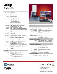
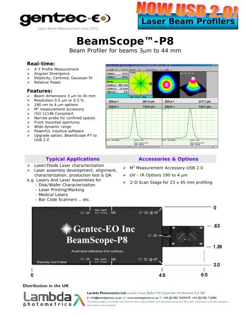
BeamScope-<strong>P8</strong><br />
Beam Profiler for beams 3μm to 44 mm<br />
Real-time:<br />
‣ X-Y Profile Measurement<br />
‣ Angular Divergence<br />
‣ Ellipticity, Centroid, Gaussian fit<br />
‣ Relative Power<br />
Features:<br />
‣ Beam dimensions 3 μm to 45 mm<br />
‣ Resolution 0.5 μm or 0.5 %<br />
‣ 190 nm to 4 μm options<br />
‣ M 2 measurement accessory<br />
‣ ISO 11146 Compliant<br />
‣ Narrow probe for confined spaces<br />
‣ Front mounted apertures<br />
‣ Wide dynamic range<br />
‣ Powerful, intuitive software<br />
‣ Upgrade option, BeamScope-P7 to<br />
USB 2.0<br />
Typical Applications<br />
‣ Laser/Diode Laser characterization<br />
‣ Laser assembly development, alignment,<br />
characterization, production test & QA.<br />
e.g. Lasers And Laser Assemblies for<br />
- Disk/Wafer Characterization<br />
- Laser Printing/Marking<br />
- Medical Lasers<br />
- Bar Code Scanners … etc.<br />
Accessories & Options<br />
‣ M 2 Measurement Accessory-USB 2.0<br />
‣ UV - IR Options 190 to 4 µm<br />
‣ 2-D Scan Stage for 23 x 45 mm profiling<br />
¼”- 20<br />
Max. depth<br />
0.2” / 6 mm<br />
M6<br />
¼”- 20 @ 45 o<br />
Gentec-EO Inc<br />
BeamScope-<strong>P8</strong><br />
¼”- 20<br />
Avoid back-reflections from surfaces<br />
Warranty void if label<br />
¼”- 20<br />
Max. depth<br />
0.2” / 6 mm<br />
M6<br />
¼”- 20 @ 45 o
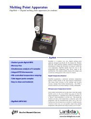
BeamScope-<strong>P8</strong> comprises a compact head, Interface box, 3 m (10 ft.) USB 2.0 cable, User Manual,<br />
Software for Windows XP or Vista.<br />
Principle of Operation: A linear scanning probe carries either a single pinhole, a single slit, or<br />
orthogonal X-Y slits. This linear scan satisfies the strict requirements of the ISO 11146 laser profiling<br />
standard*. Light passing through the slits falls onto a Silicon (190 to 1150 nm) or Germanium (800 to<br />
1800 nm) detector. [* Until the introduction of the Gentec-EO BeamScope Beam Profiler, no commercially available<br />
slit scan or knife-edge scan beam profiler met the ISO 11146 Standard. The Standard requires that the scan be<br />
performed in a plane orthogonal to the propagation axis. Drum style scanners cannot meet the Standard. Gentec-EO’s<br />
unique linear scan probe is designed to fully comply with the Standard.]<br />
Acquire Beam Profiles In Constricted Areas<br />
BeamScope-<strong>P8</strong> has made the measurement of once inaccessible beam profiles not merely possible, but simple. The<br />
unique probe-style scan head easily peers into confined axial gaps between lens, mirrors, and filters. Its ability to probe<br />
along-axis spaces as narrow as 12mm creates a whole new world of applications.<br />
No Beam Distortion From Optics Or Filters<br />
There's no distortion of the beam due to ancillary optics or filters because the BeamScope-<strong>P8</strong> doesn't need them when<br />
analyzing most type of lasers. The AUTO GAIN feature can continually adjust the detector amplifier gain to ensure full<br />
use of the 55 dB (300,000:1) gain range. Spot dimensions from 3 μm to 23 mm can be measured from a single scan<br />
head. Scan beam areas up to 23 x 45 mm with the new 2-D stage accessory.<br />
Front Mounted Apertures<br />
Front mounted apertures enable you to see precisely where the beam is being measured. Rapidly diverging and fast<br />
focusing beams are simple to capture if you can get close to your source. Now it's easier than ever to measure laser<br />
diode arrays, micro-lensed sources, broad stripe lasers, etc. Available apertures can accommodate power densities up to<br />
100 W/mm 2 onto small pinhole apertures. (Max. Total power = 0.5 W) Change apertures in minutes from slits to<br />
pinholes. This makes the BeamScope-<strong>P8</strong> an unbeatable value in beam analyzers.<br />
Notebook PC Portability with USB 2.0<br />
BeamScope now plugs interfaces to a USB 2.0 port on your notebook PC to give a portable unit with a small footprint.<br />
Perfect For R&D, QA & Production<br />
R&D users will appreciate the comprehensive range of<br />
analytical functions. QA & Production engineers will<br />
appreciate the ability to save test configurations as JOB<br />
files, and to indicate Pass/Fail on-screen.<br />
Unparalleled M 2 Measurements<br />
The BeamScope TM <strong>P8</strong> optional M2DU-<strong>P8</strong> accessory is<br />
unlike any other on the market. There are no<br />
complicated adjustments, yet the user can achieve highly<br />
repeatable measurements. The software automatically<br />
takes more frequent measurements in the waist area in<br />
order to accurately determine the true waist diameter.<br />
23 x 45 mm 2-D Scan Stage<br />
Gentec-EO’s latest beam profiling innovation offers<br />
extraordinary 0.2% (512 x 512 pixels) resolution, down<br />
to 5 x 5 μm (HxV), over beam areas up to 23 x 45 mm.<br />
2-D scan results display in the integral imaging software<br />
for area image analysis.
BeamScope<br />
Measurable Sources<br />
Measured Beam Powers<br />
Optical Dynamic Range<br />
Shape of Maximum Scanned<br />
Area<br />
Pinholes (PA series)<br />
Single Slits (SS series)<br />
X-Y Slits (XY series)<br />
2-D Stage (M2B)<br />
Measured Beam<br />
Diameters/Widths<br />
Measurement Resolution<br />
Measurement Accuracy<br />
Measured Beam Profiles<br />
Measured Profile Parameters<br />
Displayed Profiles (Note 1)<br />
Update Rate<br />
Data Analysis<br />
Pass/Fail<br />
Averaging<br />
Standard Deviation<br />
Power Measurement<br />
Source to Slit Distance<br />
Aperture sizes (Note 2 )<br />
Slits<br />
Pinholes<br />
Wavelength Range<br />
Silicon Detector<br />
Germanium Detector<br />
InAs<br />
Mounting<br />
Temp. Range (inc. Accessories)<br />
Operating<br />
Storage<br />
Minimum PC Requirements<br />
(Mac version is not available)<br />
<strong>P8</strong> Product Specifications [Subject to change without notice.]<br />
CW or<br />
Pulsed sources: >5kHz Pulse Repetition Rate @ 5% duty factor. Higher PRR is better<br />
See the graph in the Notes, below.<br />
E.g. 6 μW to 3 W, for a 1 mm diameter (1/e 2 ) Gaussian beam @ 633 nm, 5 μm slit.<br />
55 dB (= 300,000:1) [75 dB with Neutral Density 2.0 film<br />
Important: For accurate measurements, beamwidth should be < 0.5 x Scan Dimens<br />
With /EPH extended probe head, dimension 23 mm below, becomes 35 mm.<br />
Shape Cross Scan x Scanned Length<br />
Line Scan Pinhole diameter x 23 mm<br />
Rectangle 7* x 23 mm, (* 5 for Ge, 3 for InAs<br />
Trapezoid 5* x 15/5 mm, (* 3 for Ge, 2 for InAs, 3.5 x 13.5/6.5 for XYPl5)<br />
Rectangle 45 x 23 mm scanned area image. Scans a pinhole over this area.<br />
0.5 μm to ~25 mm (Defined as the 1/e 2 diameter, = 13.5% of peak for Gaussian bea<br />
0.5 μm, or 0.5% of the measured beam diameter, whichever is greater<br />
±1μm ±2% of measured beam diameter<br />
X & Y<br />
Linear & logarithmic profile display modes<br />
Gaussian beam diameter<br />
Gaussian fit<br />
Second Moment beam diameter<br />
Knife-Edge beam diameter<br />
Centroid position, relative and absolute<br />
Ellipticity + Orientation of Major Axis<br />
Beam Wander display<br />
X only, Y only, X & Y<br />
2-D plot (10,16 or 256 colors)<br />
3-D plot (10,16 or 256 colors)<br />
1 to 2 Hz. Depends upon the PC Processor Speed, Scanned Profile & Selected<br />
Options<br />
On all measured parameters, on-screen, in selectable Pass/Fail colors<br />
Beam Diameter Running Average and Accumulating Average options<br />
On Accumulation Averaging Screen<br />
Units of mW, dBm, dB, % or user entered (relative to a reference measurement<br />
provided by the user.)<br />
1.0 mm minimum<br />
Important: See Scanned Area (above ) for measurable beam dimensions<br />
2.5, 5, 10, 25 and 100 μm wide 7 mm long<br />
(Planar version of 5 μm slits are 5 mm long)<br />
5, 10, 25 and 50 μm diameter (Larger or smaller pinholes to special order)<br />
190 to 1150 nm<br />
800 to 1800 nm<br />
1500 to 4 µm<br />
¼-20 & M6 threaded mounting holes<br />
10 o to 35 o C<br />
5 o to 45 o C<br />
USB2.0 port, Windows XP or Vista; 512 MB RAM; 10 MB Hard Drive space;<br />
1024x768 monitor.
Notes:<br />
1. The 2-D and 3-D profiles are ‘reconstructed’ from the X-Y scan, making the assumption that the measured X beam<br />
profile is the same for all values of Y, and that the measured Y beam profile is the same for all values of X.<br />
2. In Single Slit or Pinhole mode, the slit/pinhole width should be ≤1/3 rd of the diameter of the beam under<br />
measurement.<br />
For X-Y slit pairs inclined at ±45 o , the ratio is approximately 1/5 th .<br />
E.g., for any beam below 20 μm diameter, use the 2.5 μm slits wherever possible.<br />
In Knife-Edge mode, the slit width should be ≥3x the beam diameter. For X-Y slit pairs inclined at ±45 o , the ratio is<br />
≥4.3 times the beam diameter.<br />
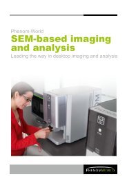
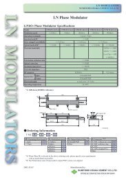
Power Limit<br />
The graph allows you to simply determine the<br />
approximate maximum CW optical power that<br />
BeamScope can measure without additional attenuation.<br />
The limit is a detector current limit.<br />
The graph shows the approximate saturation beam<br />
power in mW versus wavelength for a 100 µm diameter<br />
beam (1/e²) and a 5 µm slit.<br />
To calculate the power limit at the laser wavelength:<br />
1. Determine the plotted value, P S mW, for your<br />
wavelength (e.g. 70 mW at 633 nm).<br />
2. For a different slit or beam, multiply P S by:<br />
0.05x(beam diam., µm)/slit width, µm)<br />
3. For a pinhole, multiply P S by:<br />
0.05x(beam diam., µm)²/(pinhole diam., µm)²<br />
1000<br />
mW<br />
100<br />
Approximate saturation beam power<br />
100 μ m beam diameter, 5 μ m slit.<br />
Si<br />
InAs<br />
Ge<br />
10<br />
0.1 1 10<br />
Wavelength in μ m<br />
These slit and head damage limits always apply:<br />
• Total power on the head must not exceed 1 W, or head/slit damage may occur.<br />
• Total irradiance (power density) at any λ > 500 nm must not exceed 0.5 mW/cm² (mm of beam<br />
diameter), or slit damage may occur.<br />
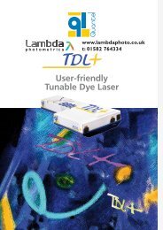
BeamScope-<strong>P8</strong> on M2DU stage<br />
<strong>P8</strong> USB 2.0 interface
Part Numbers<br />
System Examples<br />
BS8-XY5<br />
BS8-XY2.5<br />
BS8G-XY5<br />
BS8G-PA10<br />
BS8-InAs SSX<br />
/EPH<br />
PA5<br />
PA10<br />
PA25<br />
PA50<br />
SS2.5<br />
SS5<br />
SS10<br />
SS25<br />
SS100<br />
XY2.5<br />
XY5<br />
XY10<br />
XY25<br />
XY100<br />
XYPl5<br />
M2DU-BS-UV-100<br />
M2DU-BS-VIS-100<br />
M2DU-BS-NIR-100<br />
M2DU-BS-TEL-100<br />
M2DU-2D<br />
M2DU-AP<br />
P7-P7U-UPGRD<br />
P7-USB2-IF<br />
BeamScope Products & Accessories<br />
[Includes Software, 3 m long USB 2.0 cable, User Manual]<br />
Silicon Detector system with 5 μm X-Y Slit<br />
Silicon Detector system with 2.5 μm X-Y Slits<br />
Germanium Detector system with 5 μm X-Y Slits<br />
Germanium Detector system with 10 µm Pinhole<br />
Indium Arsenide Detector system with Single slit (pinholes are also available)<br />
Suffix for +10 mm Extended probe head, for probing deeper recesses<br />
Accessories<br />
Pinhole 5 μm diameter<br />
Pinhole 10 μm diameter<br />
Pinhole 25 μm diameter<br />
Pinhole 50 μm diameter<br />
Single Slit 2.5 μm wide x 3 mm long<br />
Single Slit 5 μm wide x 7 mm long<br />
Single Slit 10 μm wide x 7 mm long<br />
Single Slit 25 μm wide x 7 mm long<br />
Single Slit 100 μm wide x 7 mm long<br />
X-Y Slit 2.5 μm wide x 3 mm long @ ±45 o Planarity ± ~40 μm<br />
X-Y Slit 5 μm wide x 7 mm long @ ±45 o “ “<br />
X-Y Slit 10 μm wide “ “ “<br />
X-Y Slit 25 μm wide “ “ “<br />
X-Y Slit 100 μm wide “ “ “<br />
Dual planar X-Y Slit 5 μm wide x 5 mm long, planarity set to ± 4 μm (for tightly focused beams).<br />
M 2 Accessory, 44 mm scan/2.5 μm steps, + 3 m long USB cable + M 2 lens 400-700 nm<br />
M 2 Accessory, 44 mm scan/2.5 μm steps, + 3 m long USB cable + M 2 lens 185-450 nm<br />
M 2 Accessory, 44 mm scan/2.5 μm steps, + 3 m long USB cable + M 2 lens 630-1100 nm<br />
M 2 Accessory, 44 mm scan/2.5 μm steps, + 3 m long USB cable + M 2 lens 1030- 1800 nm<br />
Additional lenses/ focal lengths are available. Please contact us for custom configurations<br />
2D Scanning Stage 44 mm travel, 2.5 µm steps. Beam size to 23 x 44 mm with M2DU-AP plate<br />
Additional adapter plate to connect BeamScope to M2DU-2D Scanning stage.<br />
Upgrade a PCI BeamScope-P7 to USB 2.0 interfaced BeamScope-P7U with rebuilt head, calibration<br />
certificate, Interface box, USB 2.0 cables + Universal wall socket power supply and 3 year warranty.<br />
Add USB2.0 interfacing to a BeamScope-P7.. [No head rebuild, no calibration, no warranty<br />
extension.]<br />
Standard Lens<br />
Assembly<br />
(Detached for 2-D Stage<br />
operation)<br />
Stage Travel / Step<br />
Size<br />
Dimensions<br />
M2DU<br />
Weight M2DU<br />
M2DU + BeamScope-<strong>P8</strong><br />
M2 Accessory / 2D Stage Specifications<br />
Coated Achromat, λ/4 @ 550 nm ( see below for other wavelengths)<br />
Focal Length 100 mm<br />
Clear Aperture 22 mm<br />
44 mm / 2.5 μm<br />
Across axis width x Height with BeamScope x Along axis depth<br />
90 x 100 x 200 mm (5.5 x 6.5 x 8 inches)<br />
0.8 kg (1.8 lb)<br />
1.5 kg (3.3 lb)<br />
BeamMap2<br />
Beam’R2<br />
Beamage<br />
Other Gentec-EO Beam Profiling Instruments<br />
Real Time M-Squared Multi-plane profiler 0.1 micron resolution on CW lasers. XYZ profiles, XYZ focus,<br />
Centroid, Alignment, Divergence, M 2 , Visible to Telecom wavelengths. Port-powered USB2.0<br />
0.1 micron resolution on CW lasers, 0.5 micron to 4 mm beam dimensions. Port-powered USB2.0<br />
High performance, high resolution CCD imaging systems. Port-powered USB2.0