Download design-in guide - Philips
Download design-in guide - Philips
Download design-in guide - Philips

You also want an ePaper? Increase the reach of your titles
YUMPU automatically turns print PDFs into web optimized ePapers that Google loves.
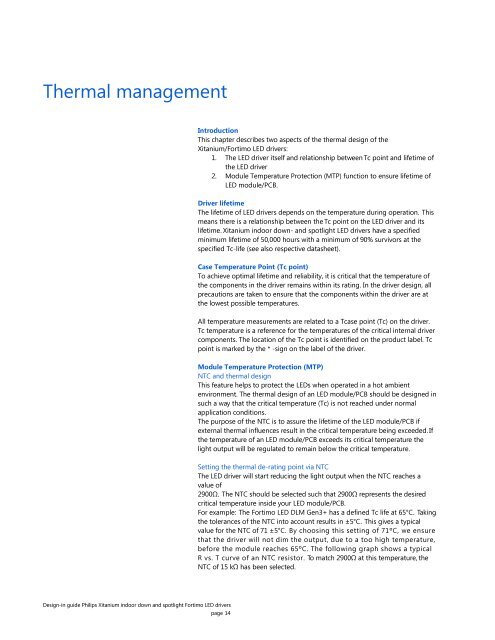
Thermal management<br />
Introduction<br />
This chapter describes two aspects of the thermal <strong>design</strong> of the<br />
Xitanium/Fortimo LED drivers:<br />
1. The LED driver itself and relationship between Tc po<strong>in</strong>t and lifetime of<br />
the LED driver<br />
2. Module Temperature Protection (MTP) function to ensure lifetime of<br />
LED module/PCB.<br />
Driver lifetime<br />
The lifetime of LED drivers depends on the temperature dur<strong>in</strong>g operation. This<br />
means there is a relationship between the Tc po<strong>in</strong>t on the LED driver and its<br />
lifetime. Xitanium <strong>in</strong>door down- and spotlight LED drivers have a specified<br />
m<strong>in</strong>imum lifetime of 50,000 hours with a m<strong>in</strong>imum of 90% survivors at the<br />
specified Tc-life (see also respective datasheet).<br />
Case Temperature Po<strong>in</strong>t (Tc po<strong>in</strong>t)<br />
To achieve optimal lifetime and reliability, it is critical that the temperature of<br />
the components <strong>in</strong> the driver rema<strong>in</strong>s with<strong>in</strong> its rat<strong>in</strong>g. In the driver <strong>design</strong>, all<br />
precautions are taken to ensure that the components with<strong>in</strong> the driver are at<br />
the lowest possible temperatures.<br />
All temperature measurements are related to a Tcase po<strong>in</strong>t (Tc) on the driver.<br />
Tc temperature is a reference for the temperatures of the critical <strong>in</strong>ternal driver<br />
components. The location of the Tc po<strong>in</strong>t is identified on the product label. Tc<br />
po<strong>in</strong>t is marked by the * -sign on the label of the driver.<br />
Module Temperature Protection (MTP)<br />
NTC and thermal <strong>design</strong><br />
This feature helps to protect the LEDs when operated <strong>in</strong> a hot ambient<br />
environment. The thermal <strong>design</strong> of an LED module/PCB should be <strong>design</strong>ed <strong>in</strong><br />
such a way that the critical temperature (Tc) is not reached under normal<br />
application conditions.<br />
The purpose of the NTC is to assure the lifetime of the LED module/PCB if<br />
external thermal <strong>in</strong>fluences result <strong>in</strong> the critical temperature be<strong>in</strong>g exceeded. If<br />
the temperature of an LED module/PCB exceeds its critical temperature the<br />
light output will be regulated to rema<strong>in</strong> below the critical temperature.<br />
Sett<strong>in</strong>g the thermal de-rat<strong>in</strong>g po<strong>in</strong>t via NTC<br />
The LED driver will start reduc<strong>in</strong>g the light output when the NTC reaches a<br />
value of<br />
2900Ω. The NTC should be selected such that 2900Ω represents the desired<br />
critical temperature <strong>in</strong>side your LED module/PCB.<br />
For example: The Fortimo LED DLM Gen3+ has a def<strong>in</strong>ed Tc life at 65°C. Tak<strong>in</strong>g<br />
the tolerances of the NTC <strong>in</strong>to account results <strong>in</strong> ±5°C. This gives a typical<br />
value for the NTC of 71 ±5°C. By choos<strong>in</strong>g this sett<strong>in</strong>g of 71ºC, we ensure<br />
that the driver will not dim the output, due to a too high temperature,<br />
before the module reaches 65ºC. The follow<strong>in</strong>g graph shows a typical<br />
R vs. T curve of an NTC resistor. To match 2900Ω at this temperature, the<br />
NTC of 15 kΩ has been selected.<br />
Design-<strong>in</strong> <strong>guide</strong> <strong>Philips</strong> Xitanium <strong>in</strong>door down and spotlight Fortimo LED drivers<br />
page 14