"MELSEC-L Series" Extension System - Mitsubishi Electric
"MELSEC-L Series" Extension System - Mitsubishi Electric
"MELSEC-L Series" Extension System - Mitsubishi Electric

Create successful ePaper yourself
Turn your PDF publications into a flip-book with our unique Google optimized e-Paper software.
TECHNICAL REPORTS<br />
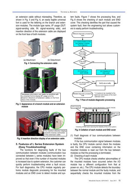
an extension cable without misreading. Therefore, as<br />
shown in Fig. 5 and Fig. 6, an easily legible universal<br />
font is used for the lettering on the branch and extension<br />
modules. The module type name, I/F usage (OUT:<br />
signal-sending side, IN: signal-receiving side), and<br />
insertion direction of the extension cable are displayed<br />
on the front face of both modules.<br />
5. Features of L Series <strong>Extension</strong> <strong>System</strong><br />
(Easy Troubleshooting)<br />
The functions for diagnosing faults of the bus<br />
communication between modules (communication bus<br />
connected between L series modules) have been improved<br />
so that even if the number of mounted modules<br />
is increased due to system extension, the customer can<br />
quickly perform troubleshooting when a fault occurs.<br />
For fault diagnostics, the CPU module regularly performs<br />
module diagnostic processing for the mounted<br />
modules and an END cover to detect module and system<br />
faults. Figure 7 shows the processing flow, and<br />
Fig. 8 shows the checking of each module and END<br />
cover. This checking identifies the part that caused the<br />
system fault, then the engineering tool allows customers<br />
to easily perform troubleshooting.<br />
(a) Attachment<br />
(b) Detachment<br />
Fig. 4 Connecting the extension cable<br />
Fig. 5 Appearance of a branch module and an extension<br />
module<br />
Fig. 7 Flow of module diagnostic processing<br />
The insertion direction display<br />
prevents reverse connection<br />
of the extension . cable.<br />
Fig. 6 Insertion direction display of an extension cable<br />
Fig. 8 Collation of each module and END cover<br />
(1) Fault diagnosis of bus communications between<br />
modules<br />
If the bus communication signal between modules<br />
is faulty, the CPU module cannot check the modules<br />
and the END cover containing information on the<br />
mounted modules is read out from the bus between<br />
modules so that the processing is terminated.<br />
(2) Checking of each module<br />
The CPU module checks whether abnormalities of<br />
the mounted modules have occurred (when the I/O<br />
module has a different configuration from that at<br />
power-on, etc.). The CPU module detects the boundary<br />
between the normal module and the faulty module, and<br />
sequentially checks the mounted modules from the<br />
<strong>Mitsubishi</strong> <strong>Electric</strong> ADVANCE June 2013 15