"MELSEC-L Series" Extension System - Mitsubishi Electric
"MELSEC-L Series" Extension System - Mitsubishi Electric
"MELSEC-L Series" Extension System - Mitsubishi Electric

You also want an ePaper? Increase the reach of your titles
YUMPU automatically turns print PDFs into web optimized ePapers that Google loves.
TECHNICAL REPORTS<br />
“<strong>MELSEC</strong>-L Series” <strong>Extension</strong> <strong>System</strong><br />
Authors: Kotaro Fujiwara* and Hirokazu Ishikawa*<br />
1. Introduction<br />
We have developed a system that can extend the<br />
number of mountable modules for the <strong>MELSEC</strong>-L series.<br />
The compact system is intended for small- and<br />
medium-sized control scales such as transportation<br />
equipment and general manufacturing equipment. Its<br />
functions, performance and operability are designed for<br />
cost performance and ease of use. Thus, the system<br />
can meet a wide range of customers’ needs. This paper<br />
introduces the features of the <strong>MELSEC</strong>-L series extension<br />
system and its development.<br />
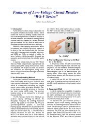
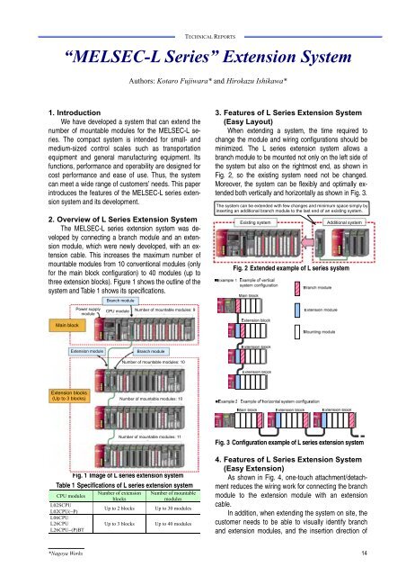
2. Overview of L Series <strong>Extension</strong> <strong>System</strong><br />
The <strong>MELSEC</strong>-L series extension system was developed<br />
by connecting a branch module and an extension<br />
module, which were newly developed, with an extension<br />
cable. This increases the maximum number of<br />
mountable modules from 10 conventional modules (only<br />
for the main block configuration) to 40 modules (up to<br />
three extension blocks). Figure 1 shows the outline of the<br />
system and Table 1 shows its specifications.<br />
Branch module<br />
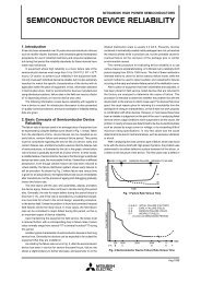
3. Features of L Series <strong>Extension</strong> <strong>System</strong><br />
(Easy Layout)<br />
When extending a system, the time required to<br />
change the module and wiring configurations should be<br />
minimized. The L series extension system allows a<br />
branch module to be mounted not only on the left side of<br />
the system but also on the rightmost end, as shown in<br />
Fig. 2, so the existing system need not be changed.<br />
Moreover, the system can be flexibly and optimally extended<br />
both vertically and horizontally as shown in Fig. 3.<br />
The system can be extended with few changes and minimum space simply by<br />
inserting an additional branch module to the last end of an existing system.<br />
Existing system<br />
Additional system<br />
Fig. 2 Extended example of L series system<br />
Power supply<br />
module<br />
CPU module Number of mountable modules: 9<br />
Main block<br />
<strong>Extension</strong> module<br />
Branch module<br />
Number of mountable modules: 10<br />
<strong>Extension</strong> blocks<br />
(Up to 3 blocks)<br />
Number of mountable modules: 10<br />
Fig. 1 Image of L series extension system<br />
Table 1 Specifications of L series extension system<br />
CPU modules<br />
L02SCPU<br />
L02CPU(−P)<br />
L06CPU<br />
L26CPU<br />
L26CPU−(P)BT<br />
Number of mountable modules: 11<br />
Number of extension<br />
blocks<br />
Up to 2 blocks<br />
Up to 3 blocks<br />
Number of mountable<br />
modules<br />
Up to 30 modules<br />
Up to 40 modules<br />
Fig. 3 Configuration example of L series extension system<br />
4. Features of L Series <strong>Extension</strong> <strong>System</strong><br />
(Easy <strong>Extension</strong>)<br />
As shown in Fig. 4, one-touch attachment/ detachment<br />
reduces the wiring work for connecting the branch<br />
module to the extension module with an extension<br />
cable.<br />
In addition, when extending the system on site, the<br />
customer needs to be able to visually identify branch<br />
and extension modules, and the insertion direction of<br />
*Nagoya Works 14
TECHNICAL REPORTS<br />
an extension cable without misreading. Therefore, as<br />
shown in Fig. 5 and Fig. 6, an easily legible universal<br />
font is used for the lettering on the branch and extension<br />
modules. The module type name, I/F usage (OUT:<br />
signal-sending side, IN: signal-receiving side), and<br />
insertion direction of the extension cable are displayed<br />
on the front face of both modules.<br />
5. Features of L Series <strong>Extension</strong> <strong>System</strong><br />
(Easy Troubleshooting)<br />
The functions for diagnosing faults of the bus<br />
communication between modules (communication bus<br />
connected between L series modules) have been improved<br />
so that even if the number of mounted modules<br />
is increased due to system extension, the customer can<br />
quickly perform troubleshooting when a fault occurs.<br />
For fault diagnostics, the CPU module regularly performs<br />
module diagnostic processing for the mounted<br />
modules and an END cover to detect module and system<br />
faults. Figure 7 shows the processing flow, and<br />
Fig. 8 shows the checking of each module and END<br />
cover. This checking identifies the part that caused the<br />
system fault, then the engineering tool allows customers<br />
to easily perform troubleshooting.<br />
(a) Attachment<br />
(b) Detachment<br />
Fig. 4 Connecting the extension cable<br />
Fig. 5 Appearance of a branch module and an extension<br />
module<br />
Fig. 7 Flow of module diagnostic processing<br />
The insertion direction display<br />
prevents reverse connection<br />
of the extension . cable.<br />
Fig. 6 Insertion direction display of an extension cable<br />
Fig. 8 Collation of each module and END cover<br />
(1) Fault diagnosis of bus communications between<br />
modules<br />
If the bus communication signal between modules<br />
is faulty, the CPU module cannot check the modules<br />
and the END cover containing information on the<br />
mounted modules is read out from the bus between<br />
modules so that the processing is terminated.<br />
(2) Checking of each module<br />
The CPU module checks whether abnormalities of<br />
the mounted modules have occurred (when the I/O<br />
module has a different configuration from that at<br />
power-on, etc.). The CPU module detects the boundary<br />
between the normal module and the faulty module, and<br />
sequentially checks the mounted modules from the<br />
<strong>Mitsubishi</strong> <strong>Electric</strong> ADVANCE June 2013 15
leftmost to the rightmost end to identify which module is<br />
faulty.<br />
(3) Checking of END covers<br />
The bus communication between modules of each<br />
block is diagnosed by checking the END cover of each<br />
block to ensure the reliability of the bus between modules<br />
in the entire system.<br />
6. Conclusion<br />
We will continue to improve the functionality, performance<br />
and operability to meet the needs of sites,<br />
while maintaining the legacy of the <strong>MELSEC</strong> programmable<br />
controllers, and will develop products that make<br />
systems easier to use.<br />
TECHNICAL REPORTS<br />
16