DSM Pocket Guidebook Volume 5: Renewable and Related ... - NREL
DSM Pocket Guidebook Volume 5: Renewable and Related ... - NREL
DSM Pocket Guidebook Volume 5: Renewable and Related ... - NREL

You also want an ePaper? Increase the reach of your titles
YUMPU automatically turns print PDFs into web optimized ePapers that Google loves.
<strong>DSM</strong><br />
<strong>Pocket</strong><br />
Guideboolc<br />
<strong>Volume</strong> 5:<br />
<strong>Renewable</strong> <strong>and</strong> <strong>Related</strong><br />
Technologies for<br />
Utilities <strong>and</strong> Buildings<br />
Western Area Power Administration<br />
<strong>and</strong><br />
U.S. Department of Energy
To convert from<br />
Conversion T•le<br />
To<br />
Muhiply by<br />
Btu (British thermal unit)<br />
elm<br />
(cubic feet per minute)<br />
oF (degree Fahrenheit)<br />
It (foot)<br />
11 2 (square feet)<br />
11 3 (cubic feel)<br />
gal (lJollon)<br />
gpm<br />
(gallon per minute)<br />
hp (horse power)<br />
in (inch)<br />
lb (pound)<br />
psi<br />
(pounds per square inch)<br />
ton<br />
(short, 2,000 lb)<br />
kWh (kilowatt hour) 2.928 X 10 -4<br />
m 3 ;s 4.719 X 10 -4<br />
(cubic meter per second)<br />
oc (degree Ceius)<br />
m (meter)<br />
(0F-32)/1.8<br />
3.048 x10<br />
2<br />
m (square meter) 9.290x10<br />
m 3 (cubic meter)<br />
-2<br />
2.831 X 10<br />
m 3 (cubic meter)<br />
-3<br />
3.785 X 10<br />
m 3 ;s<br />
-5<br />
6.309 X 10<br />
(cubic meter per second)<br />
w(wott)<br />
7.460 X 10 2<br />
m (meter)<br />
-2<br />
2.540 X 10<br />
kg (kilogmm)<br />
-1<br />
4.536x10<br />
Po (poscol) 6.895 X 10 3<br />
kg (kilogmm)<br />
-1<br />
-2<br />
9.072 X 10 2
<strong>DSM</strong> <strong>Pocket</strong><br />
<strong>Guidebook</strong><br />
<strong>Volume</strong> 5: <strong>Renewable</strong> <strong>and</strong><br />
<strong>Related</strong> Technologies<br />
for Utilities <strong>and</strong> Buildings<br />
prepared by<br />
National <strong>Renewable</strong> Energy Laboratory<br />
I 617 Cole Boulevard<br />
Golden, Colorado 80401-3393<br />
(303) 275-4099<br />
prepared for<br />
Western Area Power Administration<br />
Energy Services<br />
1627 Cole Boulevard, P.O. Box 3402<br />
Golden, Colorado 8040 I<br />
(303) 231-7504<br />
<strong>and</strong> the<br />
U.S. Department of Energy<br />
Office of Utility Technologies<br />
Washington, DC 20585<br />
(202) 586-9839
NOnCE: lhis report wos prepared os 111 occount of work sponsored by on agency of the<br />
Uned Stoles government. Neither the Un States government nor ony ogencythereol, nor<br />
ony of their employees, makes onyWD"ronty, express or implied, or ossumes onylegolliobdey<br />
or responsibiley lor the accuracy, completeness, or usefulness of 111y information, opporotus,<br />
product, or process disclosed, or represents that il5 use would not infringe private ovmed<br />
rights. Reference herein toony specific commerdol proood, process, or service bytrode nome,<br />
trademark, mmmfodurer, or otherwise does not necessori constiMe or im il5 endorw<br />
ment, remmmendotion, or favoring by the Unood States government or any agency thereof.<br />
lhe views <strong>and</strong> ojinions of authors expressed herein do not necesscri stole or reflect those<br />
of the Unood Stoles government or ony ogency thereof.<br />
Printed in the Unood States of America<br />
Available from:<br />
Notional Technicollnlormotion Service<br />
U.S. Deportment of Commerte<br />
5285 Port Royol Rood<br />
Springfield, VA 22161<br />
Price: Microfiche AD1<br />
Printed Copy AOB<br />
Codes ore used lor pricing oil publicotions.lhe code is determined by the number of pages in<br />
the publicotion.lnformotion pertaining to the pridng codes ron be found in the current issue<br />
of the loii11Ning publications which ore general ovoiloble in most librorie£ Energy Research<br />
Abstracts (ERA}, Government Reports Announmments ami lmlex (GRA ami/}, Scientific ami<br />
Technical Abstract Reports (STAR}, ond publication NTIS-PR-360 available from NTIS of the<br />
above address.
CONTENTS<br />
Brief#<br />
Page No.<br />
Foreword . . . . . . . . • . . . . . . . . . . • . . v<br />
Preface to <strong>Pocket</strong> <strong>Guidebook</strong> . . . . . . . . . . . . vii<br />
RENEWABLE RESOURCES FOR UTIUTY APPLICATIONS . . . .1<br />
1 Hydroelectric Power . . • . • • . . • . . . . . • . 1 0<br />
2 Biomass Power, Direct Conversion of Agricultural <strong>and</strong><br />
Wood Wastes • . • • . . . . . . . . . • . • . . . 19<br />
3 Municipal Solid Waste • . • . • • . • • . . . . . . 29<br />
4 Geothermal Power .. .. .. .. .. .. .. .. 37<br />
5 Solar Thermal Central Receivers . . . . . • • • . . 46<br />
6 Solar Thermal Parabolic Troughs . . • • . . . . . . 53<br />
7 Solar Thermal Parabolic Dishes . . • . . . . . . . 58<br />
8 Solt Gradient Solar Ponds . . . . . . . . . . . . . 62<br />
9 Wind Power .................... 68<br />
10 Photovoltaics • . . . . . . . . . . . . . . . . . . 81<br />
STORAGE AND RELATED TECHNOLOGIES . . . . . . . . . . 96<br />
11 Electric Energy Storage Options . . . . . • • . . . 98<br />
12 Fuel Cells . . • . . . . . . • • . . . . . . • . . 111<br />
13 Inverter Technology . . • . . . . . . . . . • . • 119<br />
RENEWABLE OPTIONS FOR BUILDING APPLICATIONS . . 122<br />
14 Solar Water Heaters . . . . . . . . . . . . . . . 126<br />
15 Passive Solar Design . . . . . . . . . . . . • • • 133<br />
16 Integrated Conservation <strong>and</strong> <strong>Renewable</strong> Design for<br />
New Commercial Buildings . . . . . . . . . . . . 142<br />
17 Ground-Source Heat Pumps . . • • • . • . • . • 145<br />
18 Photovoltaics for Building Applications . . . . . . 150<br />
iii
Page<br />
Intentionally<br />
Blank
FOREWORD<br />
In previous years of low-cost energy, renewable resource technologies<br />
were not cost effective for generating electricity on o utility scale. Today,<br />
however, with rising concern for the environment <strong>and</strong> Western Area<br />
Power Administration's (Western's) emphasis on developing integrated<br />
resource pions, the use of renewable resources, os port of on overall<br />
mix of technologies, con provide utilities with o cost-effective means to<br />
meet the Western customers' increasing dem<strong>and</strong> for reliable <strong>and</strong><br />
environmental clean power.<br />
This series of guidebooks is intended for utility personnel involved in<br />
dem<strong>and</strong>-side <strong>and</strong> supp·side planning, programs, <strong>and</strong> services. Both<br />
the novice <strong>and</strong> expert con benefit from this information. Using renewable<br />
resources to generate utility-scale power <strong>and</strong> in on·site building<br />
applications increases efficiency of resource use from o systems per·<br />
spective. Efficiency through the use of renewable resources helps<br />
Western meet two of its objectives-the elimination of wasteful energy<br />
practices <strong>and</strong> the adoption of energy-i!fficiency programs that meet<br />
customer needs in on era of diminished resources <strong>and</strong> increased<br />
environmental concern.<br />
v
Page<br />
Intentionally<br />
Blank
PREFACE TO THE<br />
POCKET GUIDEBOOK<br />
.INTRODUCTION<br />
<strong>Renewable</strong> energy sources, including wind, sunlight, water, plants, <strong>and</strong><br />
geothermal energy, represent a massive energy resource that could<br />
provide Americans with energy from dean, safe sources.<br />
The future contribution of renewobles is vast <strong>and</strong>, proper managed,<br />
virtually inexhaustible. The ultimate contribution from renewables will<br />
depend on the emphasis that the United Stutes places on the development<br />
<strong>and</strong> application of these resources. Growing evidence of significant<br />
customer dem<strong>and</strong>, coupled with a willingness to pay for power<br />
from a dean energy source, suggests that utilities need to become<br />
familiar with the renewable technologies applicable in their service<br />
territory.<br />
<strong>Renewable</strong> resources are general dse <strong>and</strong> intermiffent, <strong>and</strong> all<br />
have different regional availability. These conditions present utilities<br />
with challenges in developing <strong>and</strong> using these resources .<br />
• INTENDED AUDIENCE<br />
This guidebook is intended to be a quick reference source for utility<br />
field representatives in their customer interactions <strong>and</strong> far utility<br />
planners in the early stages of developing an integrated resource plan.<br />
It is designed to allow a quick screening of supply-side generation<br />
options <strong>and</strong> end-use building applications of renewable resources.<br />
This guidebook is directed primarily at small municipal utilities <strong>and</strong><br />
rural electric cooperatives within the Western Area Power Administration<br />
service area. Large utilities with more abundant staff capability<br />
may find the guidebook useful as a starting point. Their technology<br />
selection process will undoubtedly include review of other source<br />
documents <strong>and</strong> detailed system <strong>and</strong> engineering analyses of the<br />
options.<br />
vii
• ORGANIZATION AND USE OF THE<br />
GUIDEBOOK<br />
This guidebook is the fifth in a series of five pocket-sized volumes. The<br />
first four volumes address dem<strong>and</strong>-side management (<strong>DSM</strong>) measures.<br />
The first volume considers end-use technologies for the residential<br />
sector. The second volume includes technologies for the commercial<br />
sector <strong>and</strong> covers motors <strong>and</strong> variable-speed drives applicable to the<br />
commercial, industrial, <strong>and</strong> agricultural sectors. The third volume<br />
discusses energy-efficient technologies for the agricuhurol sector, with<br />
on emphasis on the central <strong>and</strong> western United States. The fourth<br />
volume covers technologies for industrial applications.<br />
This volume is divided into three major sections. The first section<br />
describes renewable resources available to utilities for generating<br />
electricity. The second section covers energy storage, fuel cells, <strong>and</strong><br />
inverter technology. The stomge options ore included because they con<br />
be used in conjunction with renewable uh1ity power generation technologies<br />
in some circumstances. Fuel cells ore on emerging fossil-based<br />
electric generation technology. They ore not a renewable technology,<br />
but they might be powered by hydrogen in the future. Inverter<br />
technology is included because it is used with photovoltoic systems.<br />
The third section describes renewable resources that con be used as<br />
<strong>DSM</strong> measures. The potential for solar energy in the buildings sector is<br />
enormous. Where buildings hove adequate access to the solar resource,<br />
many renewable technologies are cost-effective today.<br />
Utilities can apply renewable resources to meet customer energy needs,<br />
such as water heating, passive solar design, doighting, <strong>and</strong> the use<br />
of photovohoics in remote locations. The introduction to Section 3 of<br />
this guidebook contains a matrix that refers the reader to renewable<br />
briefs in other volumes of this pocket guide series .<br />
• METHODOLOGY/DATA<br />
For each renewable technology, the guidebook presents a short numbered<br />
"technology brief' that describes the technology, its potential<br />
applications, resource assessment, market outlook, industry status,<br />
viii
construction leod lime, environmental issues, ond lund oreo requirements.<br />
Eoch brief olso includes o summorytoble containing information<br />
on capitol costs, O&M costs, levelized energy costs, overage size per<br />
instollotion, copocity factor, ond life. Historicol ond future cost projections<br />
or trends ore presented for the technologies, where known. Costs<br />
ore expressed in 1990 dollars, unless noted.<br />
In oil coses, the costs were token from existing sources, including<br />
documentation of utility procurements, cose studies, or notional or stote<br />
studies. In some roses, manufacturers were contorted directly to obtain<br />
cost doto. The sources used varied, depending on the ovoilobility of<br />
doto ond the complexity of the technology.<br />
As might be expected, costs drown from different sources ore frequently<br />
inconsistent. The authors ottempted to reconcile such inconsistencies.<br />
The guidebook is not intended to substiMe for o detailed analysis, but<br />
it points the reader toward those technologies most likely to benefit<br />
both the end user ond the utility. For more details, the reader should<br />
consult the references ot the end of eoch brief .<br />
• DATA VARIABILITY AND UNCERTAINTY<br />
A problem with guidebooks such os this is thot the doto present only o<br />
simple overview of eoch technology. Yet mony volumes hove been<br />
written describing the oppkcotion of these technologies. Consequently,<br />
the cost estimates presented here should be used with o cleor underst<strong>and</strong>ing<br />
of the variability ond uncertainty of the source.<br />
Cost is dependent on mony factors, including:<br />
• Size of system<br />
• Economies of scole<br />
• Locution<br />
• Quotlfy of the resource<br />
• Access to transmission lines<br />
• Technology maturity.<br />
ix
For these reasons, spec:ific cost estimates ore difficuh to generate.<br />
There ore significant sources of uncertainly in cost data found in the<br />
literature. The uncertainties, which Iorge resuh from drawing cost<br />
statistics from o number of different sources, include:<br />
• Differing assumptions among studies<br />
• Lock of complete documentation of the assumptions, data, <strong>and</strong><br />
methods used in many of the studies<br />
• Lock of statistical valid generalizations because of small somple<br />
sizes (i.e., the resuhs in the referenced studies ore frequen<br />
based on on o few applications or systems.)<br />
• In some cases, the systems hove not been buih <strong>and</strong> the costs ore<br />
based on estimates. These cases ore noted os estimates.<br />
X
SECT I O N 1<br />
RENEWABLE RESOURCES FOR<br />
UTILITY APPLICATIONS<br />
.INTRODUCTION<br />
Electricity is o key to the country's economic health <strong>and</strong> quality of life.<br />
Through the integrated resource planning (IRP) process, Western Areo<br />
Power Administration (Western) customer utilities need to pion the next<br />
generation of power supplies. Utilities need to investigate the integration<br />
of renewable resources in the suppide <strong>and</strong> demondide management<br />
(<strong>DSM</strong>) options chosen for the future.<br />
Historically, the bulk of utility electric generation has been dispatchoble<br />
<strong>and</strong> bused on economies of scale. Lorge power plants offered the best<br />
economics. Today, legislators, utility regulators, <strong>and</strong> consumers ore<br />
promoting improved efficiency in the use of our energy resources,<br />
reduced dependence on fossil fuels, <strong>and</strong> o course of action that willleod<br />
to o more sustainable <strong>and</strong> secure energy future.<br />
Utilities con consider many kinds of renewable energy technologies for<br />
power generation; eoch technology has different operating <strong>and</strong> cost<br />
chorocteristics. Consider these examples:<br />
• Hydro-generation <strong>and</strong> geothermal steam-powered generation<br />
ore both long-established, inexpensive technologies that con be<br />
dispatchoble, depending on the quality of the resource.<br />
• A solar thermal power plant con produce os much energy os o<br />
conventional central station power plant. The time of maximum<br />
power output may be coincident with o utility's peak power<br />
needs.<br />
• Burning biomass-such os wood waste-become on economical<br />
fuel alternative under the encouragement of the Public<br />
Utilities Regulatory Policy Act of 1978 (PURPA), <strong>and</strong> the prevalence<br />
of these fuek makes them renewable sources.<br />
However, just os utility planners would not build o system using only<br />
one fuel source or plant, no utility planner should build o future system
using on solar, wind, or biomass energy sources. These technologies<br />
should be used os elements of on infegroted portfolio of fuel types ond<br />
technologies, exploning the odvonfoges of eoch while compensoling<br />
for their respective disodvonfoges.<br />
Mony renewable sources of energy offer significant environmental<br />
odvonfoges in terms of reduced levels of carbon dioxide, sulfur oxides,<br />
ond nnrogen oxides compared to conventional technologies. Some<br />
stoles hove recent passed regulations requiring utilmes to consider<br />
the cost of environmental impacts when choosing new sources of<br />
electricity. Other stoles hove regulations or ore considering policies to<br />
odd environmental costs to the cost of power generotion. These deve<br />
opmenls ore still in their infancy ond very controversial, but they could<br />
hove o significant impact on the power planning process.<br />
Dispersed generation, modularity, ond short construction leod limes ore<br />
additional odvonfoges of renewable resources. <strong>Renewable</strong> resources<br />
con be sized in mony copocity ranges ond con be procured quick.<br />
Utilities ore interested in dispersed ond modular facilities tho! frock<br />
load growth.<br />
Mony utilities ore finding cost-effective woys to use renewables for<br />
nongrid applications. For example, in certain opplicotions, photovokoics<br />
(PVI con supp power more economically thon installing o fronsformer,<br />
or stringing distribution lines to low-power opplicotions such os<br />
sectionolizing switches, cathodic protection devices, nudeor warning<br />
signs, or wafer pumps--even the power lines ore relotive dose by.<br />
In oddnion, utilnies con opp renewable resources to meet customer<br />
energy needs, such os solar water healing, passive solar design, or the<br />
use of PV in remote locations .<br />
• TODAY'S ECONOMICS<br />
The economics of solar technologies ond their comparison to conventional<br />
technologies involve mony factors. The reader is referred to the<br />
first reference of the end of this section for o full discussion of the<br />
economics of solar energy systems.<br />
2
<strong>Renewable</strong> <strong>and</strong> fossil technologies tend to hove opposite cost structures.<br />
The renewable plant geneml has o higher capitol cost <strong>and</strong> lower<br />
operating costs versus o noturol-gos-fired plant, which generally has o<br />
low initial cost <strong>and</strong> o higher operating cost. Table R- 1 provides o<br />
summary of the economic status of renewable resources including<br />
capitol cost, operation <strong>and</strong> maintenance cost,levelized energy cost, <strong>and</strong><br />
capacity factors. Additional information <strong>and</strong> supporting documentation<br />
con be found in the individual sections on renewable resource technologies.<br />
Because some renewable technologies ore rapid evolving, the<br />
end-()f-decode cost is expected to be much lower than todoy's cost.<br />
Today, using traditional financial planning methods, the cost of generating<br />
power from central-station-based renewobles is generally higher<br />
than from o comparable plant fired by cool. However, the recently<br />
passed Notional Energy Pocy Ad of 1992 includes seveml financial<br />
incentives for renewobles. It includes o permanent extension of the<br />
solar <strong>and</strong> geothermal 1 0% investment lox credit. It oko includes o<br />
production tax cred to power focilies equal to $0.015 for each kWh<br />
of electricity produced from solar, wind, biomass (excluding municipal<br />
solid waste), or geothermal energy. The definition of biomass requires<br />
that biomass focilies use biomass grown exclusive for energy production,<br />
to qualify for the cred.<br />
The levelized energy cost represents the present value of o resource's<br />
cost (including the initial copol cost, annual operating <strong>and</strong> maintenance<br />
costs (O&M), replacement costs, <strong>and</strong> os appropriate, cost of<br />
feedstock <strong>and</strong> ouxdiory fuel. It also includes the cost of financing. By<br />
levelizing costs, resources with different lifetimes <strong>and</strong> generating<br />
capacities con be compared. The costs presented in Table R -1 <strong>and</strong> the<br />
individual briefs do not reflect the environmental or societal benefits<br />
of using renewable resources.<br />
A capac factor is the amount of energy o system produces as o percent<br />
of the total omount thot it would produce operating at its rated<br />
capacity throughoutthe year. Higher values indicate on ability to meet<br />
o load foro greater portion ofthe year, assuming the plant is dispatched<br />
as fully as possible. Because many renewable resources ore intermittent<br />
resources, their capacity factors ore on the low end of the range when<br />
measured using traditional methods. In some circumstances,<br />
3
eneWJbles can be combined with advanced storage options. In other<br />
cases, depending on resource availability <strong>and</strong> the utility load profile,<br />
some renewable resources may have their time of peak output coincident<br />
with the lime of the utility peak dem<strong>and</strong>. Other renewables such<br />
as biomass, geothermal, <strong>and</strong> hydropower, under some circumstances,<br />
are ful dispalchable. With good planning, utilities can maximize the<br />
benefits of inlermillenl renewable resources without storage.<br />
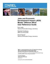
The cost of energy for new generating facilities depends on the type<br />
<strong>and</strong> purpose of the faciiHy. Cost of generation for base load, intermediate,<br />
<strong>and</strong> peaking facilities is shown in Figure R-1. Today, the cost of<br />
hydropower is cost effective. Figure R-2 illustrates cos! !rends for four<br />
renewable technologies: solar thermal, biomass, wind, <strong>and</strong> PV. In<br />
particular niche markets, they are cos! effective today on a levehzed<br />
life-cycle cost basis. Projections indicate that on a levelized cost basis,<br />
many more renewable options will be cost effective for peaking,<br />
intermediate, <strong>and</strong> some base load power generation by the year 2000.<br />
When anaing the system costs of renewables, planners are exploring<br />
valid approaches to the difficult task of incorporating the most significant<br />
element in utiiHy planning-risk. Since the 1970s, fuel cost<br />
variability, environmental policy shifts, regulatory condemnation of<br />
ful functioning plants, <strong>and</strong> siting difficulties appear to provide some<br />
strategic advantage lo the increasing use of renewables because they ·<br />
are general immune to these influences. Intuitive, if is dear that a<br />
technology that does no! require a fuel, such as solar or wind, has a<br />
value because of its immunHy from unforeseen fuel price increases.<br />
The difficult task is incorporating such facls in thoughtful ulihty planning.<br />
AI a minimum, we can say that every utility should begin now to<br />
enhance its familiarity <strong>and</strong> "h<strong>and</strong>s-an" exposure with at leas! some of<br />
these technologies.<br />
4
• FOR MORE INFORMATION<br />
PUBLICATIONS<br />
American Solar Energy Society, Economics of Solar Energy Technologies,<br />
Boulder, CO, December 1992.<br />
Hamrin, J., <strong>and</strong> N. Radar, Investing in the Future: A Regulator's Guide<br />
to <strong>Renewable</strong>s, National Association of Regulatory Utility Commissioners,<br />
Washington, D.C., February 1993.<br />
Brower, Michael, Cool Energy: <strong>Renewable</strong> Solutions to Environmental<br />
Problems (revised edition), The MIT Press, Cambridge, MA, 1992.<br />
Idaho National Engineering Laboratory, et al., The Potential of <strong>Renewable</strong><br />
Energy: An Interlaboratory White Paper, SERI/I'P-260-3674,<br />
Solar Energy Research lnstiMe, Golden, CO, March 1990.<br />
5
Table R-1. Economks of <strong>Renewable</strong> Options for Utibty·Scale Generation<br />
Current<br />
Capital Operational Levelized Cost Capacity Typkal Size<br />
Cost Cost of Eledridty Fodor per<br />
($/kWh)! ($/kWh) (%) Installation<br />
($/kW)<br />
Current Projected Current Projected<br />
(1990s) (2000) (1990s) (2000)<br />
Convenfionol 170Q- 0.028- 0.028-<br />
""'<br />
Hydropower 2070<br />
-<br />
0.002 0.063 0.063 4Q-50 >34MW<br />
Direct 60Q-<br />
Biomass 2400 83.00/kW/yr 0.079 0.074 70-85 30MW<br />
Combusfion<br />
Municipol Solid Waste<br />
310Q-<br />
(direct burn) 5100<br />
- - - -<br />
5Q-80 9·80MW<br />
Geothermal 169Q- 0.02- 0.057- 0.047<br />
Flash 2130 1900 0.04 0.064 0.055 8D-90 Under 50MW<br />
Geothermal 0.02- 0.057- 0.047<br />
Binary 2400 2087 0.035 0.064 0.055 BD-90 Under SOMW
·solor Thermal O.OBQ- 40 10Q-200MW<br />
Central Receivers<br />
-<br />
3300<br />
- -<br />
0.10 (estimated) (plonned)<br />
Solar Thermal 0.09- 0.08--<br />
Pombolic Trough 3010 2200 0.018 0.13 0.10 36 Up to BOMW<br />
Solar Thermal 0.15 23 5-25 kW<br />
Pombolic Dishes<br />
- - -<br />
0.30 (estimated) (projected)<br />
- Small Systems 300Q-6000<br />
-Lorge Systems 1700<br />
.. Solor Ponds 1,9002<br />
-<br />
0.01 0.015- 0.08- 70-90 70kW<br />
0.30 0.10<br />
Wind 1010 750 0.016 0.075 0.040 2Q-30 15Q-500 kW<br />
0.050 (machines)<br />
Photovoltoics BOOQ- 400Q- 0.36- 0.18- 25-35 Up to 500 kW<br />
15,000 5000 0.005 0.68 0.22<br />
Note: doshes indkate that data is not available (see the indiviluol briefs for more informotlon)<br />
1. Unless otherwise noted.<br />
2. Cost of engine only. See Brief B.
8<br />
C\J<br />
Ill<br />
0<br />
0<br />
0<br />
C\J<br />
0 LO 0 LO 0 LO<br />
C') C\J C\J C\J .,.... 0<br />
ci ci ci ci ci ci<br />
(LIM>!/$) JSOO lifiJaua pazuaAal<br />
0<br />
0<br />
ci<br />
0<br />
Ol<br />
Ol<br />
8
..<br />
Th<br />
4<br />
z<br />
<br />
00<br />
[<br />
0<br />
u o<br />
<br />
<br />
<br />
<br />
"5l <br />
•<br />
0.10<br />
-<br />
O.QQ __ ...,. ___,<br />
·-<br />
- - ---<br />
1990 2000 2030 1990 2000 2030 1990 2000 2030 1990 2000 2030<br />
Photovoltaics Solar Thermal Wind Biomass<br />
Electric<br />
Electric<br />
Figure R-2. Cost trends for renewable energy<br />
:g<br />
<br />
<br />
0::
R E N EWABLE BRIE F<br />
HYDROELECTRIC POWER<br />
.INTRODUCTION<br />
In 1991, hydroelectric facilities generated 275 blion kWh or about<br />
1 0% of the total net electrical generation in the United States. Hydroelectric<br />
capacity includes 18 GW of pumped hydro capacity, <strong>and</strong><br />
73.4 GW of conventional hydro capacity .<br />
• TECHNOLOGY DESCRIPTION<br />
Hydroelectric technology converts the kinetic energy contained in<br />
foltJng or flowing water into electrical energy through the use of o<br />
turbine <strong>and</strong> o generator.<br />
The capability of o hydropower plant is primarily o function of two main<br />
variables ofthe water resource: (1) flow rote expressed in ft3 /s or gpm,<br />
<strong>and</strong> (2) hydraulic head, which represents the elevation differential<br />
through which the water foils. Usually o low-head plant is less than<br />
100 ft (30.5 M), o medium-head plant ranges from 100 to<br />
800 ft (243.8 M), <strong>and</strong> o high-head plant is 800 ft (243.8 M) or more.<br />
Because power generation is dependent on both head <strong>and</strong> flow, similar<br />
generation capacities con be developed by either o low-head, high-flow<br />
oro igh-heod, low-flow facility or some combination of the two.<br />
Hydropower technology con be categorized into two types: conven·<br />
tionol <strong>and</strong> pumped storage. Conventional hydropower uses the available<br />
water from o river or reservoir to produce electricity. The annual<br />
amount of electrical generation con depend indirectly or directly on the<br />
amount of rainfall in o river basin <strong>and</strong> whether water storage foa1ilies<br />
ore port of the project. A pumped storage facility stores electrical<br />
energy by pumping water, usually through reversible turbines, from o<br />
lower to on upper reservoir. Electricity is generated when the water<br />
flows bock through the turbines to the lower reservoir. More energy is<br />
required in the pumping than is produced by the ant, (typically<br />
1.25 kWh to 1.4 kWh required for each kWh generated), but the<br />
pumping is done during the low-power dem<strong>and</strong> hours. Pumped-storage<br />
facilifies ore valuable to the utilty because they con operate economi:olly<br />
10
<strong>and</strong> be brought on-line quick during the high-power dem<strong>and</strong> periods.<br />
The amount of annual electrical energy generation from the reservoir<br />
depends on the utility's need for energy storage <strong>and</strong> the facility's<br />
capacity.<br />
The main types of conventional hydropower plant operation are: run<br />
of river, peaking, <strong>and</strong> storage:<br />
•<br />
The run-of-river project uses the river flow with very little<br />
aeration <strong>and</strong> little or no impoundment of the water.<br />
• In a peaking project, the hydropower plant is operated at<br />
maximum allowable capacity for part of the day <strong>and</strong> is either<br />
shut down for the remainder of the time or operated at minimal<br />
capacity level.<br />
• A storage project stores water during high-inflow periods to<br />
augment water during low-inflow periods. Storage projects allow<br />
the flow releases <strong>and</strong> power production to be more flexible <strong>and</strong><br />
dependable. Many hydropower project operations use a combination<br />
of approaches.<br />
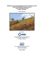
Conventional hydropower ants generaly have the following components:<br />
• Dam--
Agure R-3 illustrotes these components.<br />
Hydroelectric technology is highly developed. The efficiency of the<br />
turbine, which is based on losses of effective head in the turbine,<br />
normally range from 80% to 90% .<br />
• DEFINITIONS AND TERMS<br />
BULB TURBINE The entire generalor is mounted inside the wafer<br />
passageway as an integral unit with the turbine. These installations can<br />
offer significant reductions in the size of the powerhouse.<br />
PELTON TURBINE Water posses through nozzles <strong>and</strong> strikes cups<br />
arranged on the periphery of a runner, or wheel, which causes the<br />
runner to rotate, producing mechanical energy. The runner is fixed on<br />
a shaft, <strong>and</strong> the rotational motion of the turbine is lransmilled by the<br />
shaft to the generator.<br />
FRANCS TURBINE Contains a runner that has wafer passages<br />
through if formed by curved vanes or blades. As the water passes<br />
through the runner <strong>and</strong> over the curved surfaces, if causes rofafion of<br />
the runner. The rofafional mofian is transmitted by a shaft to the<br />
generator.<br />
PROPELLER TURBINE Contains a runner that has blades similar to<br />
a propeller used to drive a ship. As wafer posses over the curved<br />
propeller blades, if causes rotation of the shaft to which the blades are<br />
allached.<br />
KAPLAN TURBINE Equipped with two blades whose pitch is adjustable.<br />
The turbine may have gales to control the angle of the flow into<br />
the blades .<br />
• RESOURCE ASSESSMENT<br />
In 1992, the Federal Energy Regulatory Commission IFERCJ <strong>and</strong> the<br />
Idaho National Engineering Laboratory identified the undeveloped<br />
hydropower potential at 71,399 MW--approximale 9% at deve<br />
oped sites that currently gene role power, 47% at undeveloped sites with<br />
dams, <strong>and</strong> 44% at undeveloped sites without dams. The undeveloped<br />
12
potential is loroted of 4540 ses ranging from small to Iorge. The<br />
undeveloped potential for pumped storage is 1,632,919 MW ot 1405<br />
sites, on on overage 1162 MW/site.<br />
Figure R-4 shows hydropower copodty in the Uned Stoles .<br />
• MARKET OUTLOOK FOR HYDRO-<br />
ELECTRIC POWER<br />
Hydroelectric is on established technology. It has been in use in the<br />
Uned Stoles since the 1800s. Rother than building new Iorge dams,<br />
current markets include increasing output of existing plants, adding<br />
generation copobiMties to existing dams, developing small low-head<br />
plants, <strong>and</strong> developing pumped storage systems.<br />
The FERC predicts that pumped storage will like represent most of the<br />
growth in U.S. hydroelectric generating capac over the next few<br />
decodes .<br />
• INDUSTRY STATUS<br />
Efficient turbine designs for various head <strong>and</strong> discharge conditions ore<br />
available from o Iorge number of manufacturers. Hydroelectric industry<br />
directories such os Hydro-Reviewond Independent Energy list many<br />
manufacturers <strong>and</strong> services available to developers .<br />
• CONSTRUCTION LEAD TIME<br />
The hydropower licensing process for o major facility overages 4 to 7<br />
years. For small futilities overages 2to 4 years. Construction lead<br />
time is estimated to be 4 years for Iorge hydroelectric plants <strong>and</strong><br />
2 years for small facilities .<br />
• ENVIRONMENTAL ISSUES<br />
Hydropower plants con hove impacts on the environment. The streamflow<br />
is o renewable resource, <strong>and</strong> hydroelectric generation is not o<br />
consumptive use of water, okhough Iorge surface areas of reservoirs<br />
increase the evaporative loss of water. No greenhouse gases ore<br />
produced, <strong>and</strong> no solid waste is generated by o hydroelectric plant.<br />
However, impoundment of o river or stream akers the riparian habitat,<br />
<strong>and</strong>, in some cases, the water temperature, <strong>and</strong> the dissolved oxygen<br />
13
content of the released woter; if may block the migration of fish. By<br />
proper design, many of these problems con be mitigated, but siting<br />
difficulties con be expected to remain significant.<br />
• LAND AREA REQUIREMENTS<br />
Lorge hydroelectric plants ohen require vast amounts of l<strong>and</strong> for their<br />
reservoirs; however, many existing dams may be suitable for hydroelectric<br />
development. Small projects require less l<strong>and</strong> .<br />
• CURRENT COSTS AND TRENDS<br />
Table R-3 provides informofion on current costs for hydroelectric plants .<br />
• FOR MORE INFORMATION<br />
PUBLICATIONS<br />
Hydro Review Magazine <strong>and</strong> Hydrowire Newsletter ore available from<br />
HCI Publications, 4 I 0 Archibald St., Kansas Clfy, MO 64 Ill -3046,<br />
(81 6) 931-I 31 I.<br />
Hydroeledric Power Resources in the United States: Developed <strong>and</strong><br />
Undeveloped, I 992, Washington 0.(, Federal Energy Regulatory<br />
Commission.<br />
Independent Energy Magazine, available from Marier Communications,<br />
Inc., 620 Central Avenue North, Milaca, MN 56353, (612)<br />
983-6892.<br />
ORGANIZATIONS<br />
Notional Hydropower Associofion, 555 I 3th St., NW, Suite 900 East,<br />
Washington, D.C. 20004, (202) 637-81 I 5.<br />
14
Table R-2. Types of Turbines versus Application<br />
Power ,<br />
Design<br />
System Capacity Head Flow<br />
Type Efficiency (kW) Application (It) (ft3/s)<br />
Impulse Pelton 90% 7-300,000 200 It (61 M) to several thous<strong>and</strong> It of heod 4D-6,500 1-1,000<br />
;:;:;<br />
Reaclion Francis 90%-95% 7-600,000 25 It (7.6 M) to 1000 It (305M) 12-2,300 4-25,000<br />
of heod can be mounted horizontal or vertical<br />
Propeller or "axial flow"
Table R-3. Hydropower: Costs<br />
Levelized Typical<br />
Capital Cost of Size per Capadty<br />
System Cast Operational Electridty lnstallation4 Factar Life<br />
Type ($/kW) Cost ($/kWh) (MW) (%)<br />
Convenfional 17Q0-2070 F<br />
if: 6 oMX'<br />
0.028 -0.0632<br />
(yr)<br />
34 4Q-50 50+<br />
..<br />
Pumped Storoge 80Q-12001 Fixed $5.30/kW/yr 0.086-Q.l ]3 464 30 SOt<br />
Vaooble 0.005/kWh<br />
1. Capitol <strong>and</strong> operofionol com for conventional ond pumped storoge (in 1986 dollms) were token from Idaho Notional Engineering loborotory et ol., The Potenool of Kenewable<br />
Energy, SERI/fP·26(}3694, March 1990.<br />
2. Radar, N., Power Surge, Washington D.C., Public Citizen, Moy 1989 (1989 dolkns).<br />
3. California Energy Commission, Energy Technology Stutus Keport Appendix A, June 1991 ( 1987 dollars).<br />
4. Idaho Notional Engineering loborotory ond the Federol Energy Regulatory Commission, Hydropower Resource Assessment Doto Bose, 1992.
...<br />
Trash rack<br />
(keeps fish<br />
<strong>and</strong> debris<br />
out of plant)<br />
Penstock<br />
-<br />
"'».<br />
'<br />
Powerhouse<br />
.. , .,, ::?''
OLPC: 'EMO-lS·OO<br />
...<br />
..<br />
!I:<br />
0<br />
..<br />
2<br />
:::!: <br />
<br />
"'J.<br />
::c 0 lCl :::1:<br />
.;. :::1: 0<br />
I C}l 0<br />
Cll: >- 0 6 0 lCl<br />
!!j v 0 0 C\1<br />
II<br />
:D ..<br />
e Dill<br />
18
R E N E W ABLE B R I E F 2<br />
BIOMASS POWER, DIRECT<br />
CONVERSION OF AGRICULTURAL<br />
AND WOOD WASTES<br />
.INTRODUCTION<br />
Todoy's biomass resources ore essential byproducts from agriculture,<br />
forestry, <strong>and</strong> food processing. Wood-fired systems account for 88% of<br />
todoy's total biomass capacity, followed by l<strong>and</strong>fill gas (8%), agricultural<br />
wastes (3%), <strong>and</strong> anaerobic digesters (1 %). Wood con be classified<br />
as harvested or non harvested. Harvested .wood includes wood from<br />
logging <strong>and</strong> forest management activities, l<strong>and</strong> clearing, <strong>and</strong> "clean"<br />
mill residue such as slobwood from primary forest mills. Nonhorvested<br />
wood includes wood waste from municipal, industrial, <strong>and</strong> commercial<br />
waste streams. Agricultural wastes include prunings from local orchords,<br />
vineyards, bagasse, rice hulk, rice straw, nut sheik, crop<br />
residues, <strong>and</strong> manure .<br />
• TECHNOLOGY DESCRIPTION<br />
Most of the existing installed capacity is conventional, where biomass<br />
is burned to produce steam, <strong>and</strong> the steam is used to produce power<br />
in a steam turbine. Approximate 4% of todoy's primary energy<br />
dem<strong>and</strong> is met by biomass.<br />
The electricity produced from biomass is general dispotchoble rather<br />
than intermittent in nature; it is, therefore, available on a dem<strong>and</strong><br />
basis. Most of the installations to dote ore small-scale cogeneration<br />
systems operated by independent power producers or industrial entities<br />
such as pulp or paper mills. Utilities hove been involved in on a<br />
h<strong>and</strong>ful of dedicated wood-fired plants in the 40- to 50-MW range.<br />
For continued growth in the biomass power industry, utility experience<br />
is confirming that a reliable <strong>and</strong> abundant supp of low-cost biomass<br />
feedstock is required. Biomass energy forms, or dedicated feedstock<br />
supply systems (DFSS), will satisfy this requirement <strong>and</strong> limit the need<br />
to harvest natural forests. The feedstock potential could easily lead to<br />
more than 20 GW of new capacity by 201 0.<br />
19
• DEFINITIONS AND TERMS<br />
ANAEROBIC DIGESTION The process by which organic matter is<br />
decomposed by bacteria that wo rk in the absence of air.<br />
COGENERATION The process in which fuel is used to prod uce heat<br />
fo r a bo iler·steam turbine or gas fo r a turbine. The turbine drives a<br />
generator that produces electricity, with the excess heat used fo r process<br />
steam. Refer to Brief 31 in the <strong>Pocket</strong> <strong>Guidebook</strong>, <strong>Volume</strong> 4: Industrial<br />
Technologies fo r mo re informatio n.<br />
ENERGY CROPS Grown specifically fo r their fuel value. These<br />
indude food cro ps such as co m <strong>and</strong> sugarcane, <strong>and</strong> no nfood cro ps such<br />
as po plar trees <strong>and</strong> swit chgross. Current, two energy crops ore under<br />
develo pment: short rotatio n woody crops, which ore fast- growing<br />
hardwood trees harvested in 5to 8 years; <strong>and</strong> herbaceous energy cro ps,<br />
such os perennial grosses, which ore harvested annually after taking<br />
2to 3 years to reoch full pro ductivity .<br />
GASIFICATION A process in which o so lid fuel is co nverted into o gas.<br />
Production of o dean fuel gas makes o wide variety of power options<br />
available.<br />
PYROLYSIS The thermal decomposition of biomass at high temperotures<br />
(over 400°F) in the absence of air. The end pro duct of py ro sis<br />
is o mixture of so lids (char), liquids (oxygenated oi), <strong>and</strong> gases<br />
(methane, carbo n mo noxide, <strong>and</strong> carbon dioxide) with proportions<br />
determined by operating temperature, pressure, oxygen co ntent, <strong>and</strong><br />
other co nditions .<br />
• RESOURCE ASSESSMENT<br />
Biomass wastes ore currently the primary fuel so urce fo r biomass power<br />
facilities. Eno ugh wastes ore eco no mically available to allow the<br />
biomass industry to exp<strong>and</strong> mo destly thro ugh the 1990s. The U.S.<br />
Depo rtment of Energy (DOE)-sponsored energy crop development<br />
progrom is expected to dro mo licol exp<strong>and</strong> future ovoilo bility of<br />
biomass feedsto cks. Agure R- 5 shows the locotion of existing biomass<br />
feedstocks, <strong>and</strong> Agure R- 6 shows the lo cation of herbaceous <strong>and</strong> woody<br />
energy crops productio n potential.<br />
20
• MARKET OUTLOOK FOR BIOMASS<br />
Current markets include<br />
•<br />
Sites with a stable <strong>and</strong> free or inexpensive supp of harvested<br />
or nonhorvested waste materials, where the source of the waste<br />
is general within 50 miles (80.4 kml of the power plant<br />
•<br />
Utilities that hove on urgent need to reduce their pollutant<br />
emissions<br />
• Municipal utilities where the power station con solve two problems:<br />
generation of commercial power <strong>and</strong> consumption of<br />
urban wood wastes that would otherwise be londfilled<br />
• Industrial companies with on-site waste or access to a utility that<br />
needs power.<br />
Near-term market considerations:<br />
• Wood <strong>and</strong> wood wastes will continue to be primary feedstock<br />
through the end of the decode. Dedicated energy crops come<br />
into use by 2000.<br />
• Utilities willing to comp with Phose Ill of the Oean Air Act may<br />
cofire biomass at existing cool plants.<br />
• Small commercial-scale gasifiers <strong>and</strong> pyrosis reactors will be<br />
developed <strong>and</strong> tested.<br />
•<br />
· Larger-scale projects will be demonstrated that will justify the<br />
higher cost of high-efficiency boilers <strong>and</strong> steam turbine cycles.<br />
Market considerations beyond 2000:<br />
• Dedicated energy crops will serve as the primary feedstock.<br />
• Advanced technology for intermediate <strong>and</strong> bose load generation<br />
of power will be available.<br />
• Rring of biomass-derived fuel will be used for peaking <strong>and</strong><br />
intermediate load applications.<br />
21
.INDUSTRY STATUS<br />
Independent power producers hove developed the majority of dedicated<br />
wood-burning generating stations in the country <strong>and</strong> ore seltlng<br />
the energy, under the Public Utility Regulatory Policies Act of 1978, to<br />
utilities_ Although most of these plants burn forest ond mill wastes, o<br />
few developers hove begun building plants designed to burn recycled<br />
wood. Power plants that burn o variety of biomass wastes ore gaining<br />
favor in the United Stutes, particularly with the development of boilers<br />
ond fluidized bed combusters that con h<strong>and</strong>le multiple fuel types more<br />
eosi thon conventional boilers. As o result, the number of plants that<br />
either cofire agricultural wastes with wood or use agricultural wastes<br />
os the sole fuel is growing.<br />
The major market forces driving additional development of biomass<br />
power include<br />
• Availability of low-cost fuel resources, whether from waste or<br />
dedicated fuel crops, coinciding with o regional need for power<br />
• Public reaction to biomass combustion, especially urban waste<br />
wood<br />
• The ovoilobility of utility power purchase contracts<br />
• The ability of biomass to compete in utility industry solicitations<br />
• Competitiveness of biomass ompored with noturol gos<br />
• Competition for dedicated biomass crops, such os paper<br />
• The success of some local efforts to recycle or compact waste<br />
• Stote ond public support of the C02 neutral concept of biomass<br />
power<br />
• The $0.01 S per kWh tox incentive in the Energy Policy Act of<br />
1992 for biomass electric focilnies that use dedicated biomass<br />
crops .<br />
• CONSTRUCTION LEAD TIME<br />
Once o site is selected, permitting tokes approximate 0. 4 to I years<br />
for o S-to 25-MW plant. (The bolonce of engineering required to bring<br />
the plant to startup ond commercial operation is about I.S years.) The<br />
total time from site selection through commercial operation is approximate<br />
2 to 3 years. These estimates do not include the time for<br />
obtaining fuel supp contracts ond power purchase agreements, ond<br />
22
finding o suitable site. The time required for permitting is high sitespecific<br />
.<br />
• ENVIRONMENTAL ISSUES<br />
In comparison to burning cool, biomass combustion offers significant<br />
environmental benefits through reduced emissions of S02, N02, <strong>and</strong><br />
ash. Biomass is virtually free of sulfur <strong>and</strong> thus eliminates the precursor<br />
of S02 <strong>and</strong> acid rain. The growth of biomass resources provides o sink<br />
for atmospheric C02 that offsets the combustion emissions of C02 from<br />
biomass electricity production-thus providing o power option that is<br />
C02 neutral. The level of particulates is higher from burning biomass<br />
than from cool.<br />
Water quality impacts of biomass systems ore potentially less than<br />
cool-fueled system impacts. Water usage by combustion is comparable<br />
to cool-fueled systems. Feedstock growth may require Iorge quantities<br />
of water <strong>and</strong> petro-chemical-based fertilizer, which raises concerns<br />
about nutrient run-off <strong>and</strong> the absolute renewable nature of the<br />
biomass feedstock. The harvesting ond h<strong>and</strong>ling of wood presents<br />
occupational hozords comparable to cool mining. Biomass power production<br />
hos fewer long-term heoh risks thon cool-fired systems (for<br />
example, chronic lung disease). long-term ecological effects ond the<br />
sustoinobility of soil productivity ore issues unique to the biomass fuel<br />
resource, but present indications suggest that it is possible to enhance<br />
the quality of forests through appropriate monogement techniques .<br />
• LAND AREA REQUIREMENTS<br />
To generate 150 MW of electricity, 64,000 acres (25,900 hoi of lond<br />
would be required for growing low-cost, high-productivity energy crops<br />
such os woody crop fuels or perennial grosses. Approximate 1/7 of<br />
the 64,000 acres would be harvested annually. This is approximately<br />
60 acres per MW (24.6 ho/MWI .<br />
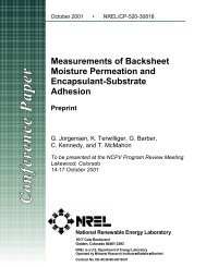
• CURRENT COSTS AND TRENDS<br />
Tobie R-4 summarizes current costs. Figure R-7 illustrates the projected<br />
future levelized costs to gene rote electricity from biomass using various<br />
conversion processes.<br />
23
Reduced capnal costs will come from improved collection, processing,<br />
<strong>and</strong> fuel feeding systems. Efficiency can be increased <strong>and</strong> emissions<br />
reduced if direct-fired combustion equipment can be fine-tuned to the<br />
particular fuel being burned. In addition, the development of small<br />
integrated systems could potentially increase resource utilization .<br />
• FOR MORE INFORMATION<br />
PUBLICATIONS<br />
Electricity from Biomass: A Developmental Strategy, U.S. Department<br />
of Energy, Washington D.(, Office of Solar Energy Conversion, April<br />
1992.<br />
Biomass State-of-the-Art Assessment, Electric Power Research lnstOOte,<br />
Palo Alto, CA, EPRI GS-7 471, September 1991.<br />
Turnbull, J.H., PG&E BiamaS$ Qualifying Focibties, lessons Leornecl<br />
Scoping Study - Phase 1, Pacific Gus <strong>and</strong> Electric Co., Report no. 007-<br />
91.5, Son Ramon, CA, May 1991.<br />
ORGANIZATIONS<br />
Western Area Power Administration, Western Regional Biomass Energy<br />
Program, 1627 Cole Blvd., P.O. Box 3402, Golden, CO 80401, (303)<br />
231-1615.<br />
U.S. Department of Energy, Solar Thermal <strong>and</strong> Biomass Power Division,<br />
1000 Independence Ave. SW, Washington, D.C. 20585, (202) 586-<br />
6750.<br />
National Wood Energy Association (NWEA), 777 North Capitol St. NE,<br />
Washington, D.C. 20002, (202) 408-0664.<br />
National <strong>Renewable</strong> Energy Laboratory (<strong>NREL</strong>), 1617 Cole Blvd.,<br />
Golden, CO 80401, Richard Rain, Biomass Power Program, (303)<br />
231-7346.<br />
24
Table R-4. Biomass: Costs<br />
Levelized Typical<br />
Capital Operational Cost of Size per Capadty<br />
System Cost1 Cost2 Electricity lnstallationl Factor Ufe<br />
Type ($/kW) ($/kW/yr) ($/kWh)<br />
(%) (yr)<br />
Direct combusflon 602400 83 0.079 30 70-85 2HO<br />
(MW)<br />
t;:l<br />
1. The cost to build o biomoss plont vories tremendously. A smoll plont (under 12 kW) built with rebuilt boirs ond turbines, bosic deionizing woter·treotment, ond stripped down<br />
controls would cost in the runge of $600 to $800/kW. At the other extreme, o highiech facility using o fluidized bed to burn ogriculturol resue with the lotest oir emission<br />
control ond zero dischorge woter system moy cost in the runge of $2000 to $2400/kW. (Source: Pacific Gos ond Electric Co., Moy 1991, Report No. 007·91.5, Son Romon,<br />
CA, Turnbull, J., PG&E Biomass Qualifying FaciDties Lessons Learned Scoping Study- Phase 1).<br />
2. Murch 8, 1993 updote to U.S. Deportment of Energy, Electricity from Biomass: A Developmental Strategy, Office of Sor Energy Conversion, Washington, D.C., April 1992.<br />
3. Represents the average size of plonts in Colifornio.
Sr----.<br />
• O&M cost<br />
7<br />
Ill] Levelized cost<br />
6<br />
5<br />
3<br />
2<br />
0<br />
Steam Steam BIG/ BIG/ BIG/ Coal/<br />
(CA) (VT) gas STIG C C ISTIG<br />
turbine<br />
Type of plant<br />
BIG = Biomass Integrated Gasification<br />
STIG = Steam Injection Gasification<br />
ISTIG = lntercooled Steam Injection<br />
Gasification<br />
T = Gas Turbine<br />
CC = Combined Cycle<br />
Figure R-7. Comparative biomass process costs<br />
28
RENEWABL E B RIE F 3<br />
MUNICIPAL SOLID WASTE<br />
• INTRODUCTION<br />
The U.S. Environmental Protection Agency (EPA) has estimated that U.S.<br />
municipal solid waste (MSW) totaled 196 million tons (177 billion kg)<br />
in 1990 <strong>and</strong> will grow over the next decade of the rote of 1.5% per<br />
year. At present, 67% of oil MSW is londfilled, <strong>and</strong> -17% is combusted<br />
in 145 municipal waste combustors.<br />
MSW facilities ore typically operated by municipalities, waste management<br />
districts, or private companies. 8ectric utility use of MSW is not<br />
widespread, although o few utilities ore using it, including one in<br />
Minnesota that operates two plants that process MSW into o refusederived<br />
fuel (RDF). This RDF serves os the fuel source for two of the<br />
power plants in the 30-MW range .<br />
• TECHNOLOGY DESCRIPTION<br />
The five major technologies common used for MSW management ore<br />
• Collection/separation of recyclable materials<br />
• Londfilling<br />
• - Moss burn for energy recovery<br />
• Production <strong>and</strong> combustion for RDF<br />
• Composting.<br />
Many communities use more than one technology to manage MSW. A<br />
solid waste management strategy should look ot volume reduction first,<br />
<strong>and</strong> then reusing, recycling, <strong>and</strong> the composting of MSW. Although<br />
energy is notthe primary goal of any MSW monogementstrotegy, moss<br />
burn <strong>and</strong> combustion of RDF offer the added benefit of energy<br />
recovery. These technologies, <strong>and</strong> the cofiring of RDF <strong>and</strong> cool, ore the<br />
focus of this brief •<br />
• DEFINITIONS AND TERMS<br />
MASS BURN FACILITY A facility in which the pretreatment of the<br />
MSW includes only inspection <strong>and</strong> simple separation to remove<br />
29
oversize, hozordous, or explosive moteriols. Moss burn facilities con be<br />
Iorge, with capacities of 3000 tons (2.7 milhon kg) of MSW per day<br />
or more. They con be scoled down to h<strong>and</strong>le the woste from smaller<br />
communities, ond modular plants with copocities os low os 25 tons<br />
(22.7 thousond kg) per day hove been buik. Moss bum technologies<br />
represent over 7 5% of oil the MSW-to-energy facihlies constructed in<br />
the United Stotes to dote. The major components of o moss burn facility<br />
include<br />
• Refuse receiving ond h<strong>and</strong>ling<br />
• Combustion ond steam generolion<br />
• Flue gos cleaning<br />
• Power generotion<br />
• Condenser coohng woter<br />
• Residue hauling ond storage.<br />
RDF To produce RDF, mixed MSW is shredded, ond noncombustible<br />
moteriols such os gloss ond metols ore generally removed. The residual<br />
moteriol is sold os·is or further densified ond/ or reduced in size to be<br />
used os RDF. The RDF processing facility is typically locoted neor the<br />
MSW source, while the RDF combustion foo1ity con be locoted elsewhere<br />
because the RDF con be transported more economically.<br />
Existing RDF facilities process between 100 (90.7 thousond kg) ond<br />
3000 tons (2.7 milhon kg) per day. The notion's largest RDF waste-to<br />
energy facility is in Florida. It processes 18,000 tons (16.3 milhon kg)<br />
per week. A facility in Minnesota processes 1 500 tons ( 1.36 million kg)<br />
per day, which serves os the fuel source for two 30-MW power plants.<br />
COFIRING WITH COAL Between 1972 ond 1988, nine U.S. ull1ities<br />
cofired almost 1 million tons (907 million kg) of RDF with cool or oil.<br />
The cofiring wos done in facilities ranging from 35-MW to 364-MW in<br />
size. Currently, on six utihties cofire RDF with cool. They ore locoted<br />
in Ames, lowo; Madison, WISConsin; Lokelond, Florida; Baltimore,<br />
Maryl<strong>and</strong>; Big Stone Gty, South Dakoto; ond Tacoma, Washington. The<br />
other utitlfies discontinued operolion for various reasons, including<br />
uneconomical production of RDF <strong>and</strong> the use of boilers not well-suited<br />
to RDF cofiring.<br />
30
• RESOURCE ASSESSMENT<br />
The MSW resources vary by regional demographics. Figure R-8 illustrates<br />
the relative distribution of MSW .<br />
• MARKET OUTLOOK FOR MSW<br />
The current market consists of municipalies responding to the need to<br />
manage <strong>and</strong> reduce the volume of MSW in their community, in addition<br />
to responding to increased customer dem<strong>and</strong> for more sustainable<br />
approaches.<br />
Using MSW for electricity production frequently is not competitive with<br />
the cost of generating electricity from fossil fuels, but the price received<br />
for the electricity can be an attractive offset to the cost of waste<br />
management. As l<strong>and</strong>fill availabil decreases <strong>and</strong> tipping fees <strong>and</strong><br />
transportation costs to l<strong>and</strong>fills increase, municipalities may become<br />
increasingly interested in these options. Figure R-9 illustrates the range<br />
of 1991 tipping fees, by state.<br />
Current projections of decreasing l<strong>and</strong>fill capacity <strong>and</strong> increasing waste<br />
generation wl11 1ead to dem<strong>and</strong> for waste volume <strong>and</strong> weight reduction<br />
alternatives such as woste-to-energy combustion .<br />
• INDUSTRY STATUS<br />
Most waste-to-energy plants have been developed through an alliance<br />
between a developer/vendor <strong>and</strong> the governmental body responsible<br />
for waste disposa municipality, county, district, or regional waste<br />
authority. A public e may contract with a full-service vendor to build<br />
<strong>and</strong> operate a waste-to-energy facil for 20 to 30 years.<br />
Numerous power plant engineering companies offer design <strong>and</strong> construction<br />
services .<br />
• CONSTRUCTION LEAD TIME<br />
The estimated lead time to build an MSW project is 1to 2 years. Public<br />
opposition can extend the lead time up to 5 years.<br />
31
• ENVIRONMENTAL ISSUES<br />
Under Section 306 of the Oeon Air Act amendments passed in 1991,<br />
the EPA will be required, by 1993, to issue ocid gos emission stondords<br />
for MSW facilities with copocities of 250tons (22.6 kg) per doy or more .<br />
• LAND AREA REQUIREMENTS<br />
The maximum copocity of o l<strong>and</strong>fill is determined by volume, not<br />
weight. The lund oreo used for MSW monogement is largest oil woste<br />
is londfilled, ond smallest oil woste is burned ond the osh from<br />
combustion is londfilled. A l<strong>and</strong>fill with gos recovery (on increasingly<br />
common type of focility) requires 1.6 yd3 (1.2 m3) per ton of MSW. In<br />
comparison, the wostefrom moss burningofoton ofMSWonrequires<br />
0.2 yd3 (0.15 m3) per ton. Direct firing of RDF requires 0.4 yd3<br />
(0.3 m3) perton .<br />
• CURRENT COSTS AND TRENDS<br />
Tobie R-5 presents current cost information for various types of MSW<br />
conversion techniques .<br />
• FOR MORE INFORMATION<br />
PUBLICATIONS<br />
SRI Intemotionol, Data Summary of Municipal Solid Waste Management<br />
Ahernatives <strong>Volume</strong> 1: Report Text, NREI/IP-431-4988A, Menlo<br />
Pork, CA, October 1992.<br />
Solid Waste <strong>and</strong> Power, Journal ovoiloble from HCI Publications,<br />
410 Archibald St., Konsos Oty, MO 64111-3046, (816) 931-1311.<br />
li'ash to (ash, Investor Responsibility Research Center, 1755 Mossochusetts<br />
Ave. NW, Sune 600, Washington, D.C. 20036, (202) 234-7500,<br />
September 1991.<br />
1991-1992 Resource Recovery Yearbook, Governmental Advisory Associates,<br />
177 E. 87th St., Suite 400, New York Qty, NY 10128, (212)<br />
410-4165.<br />
32
ORGANIZATIONS<br />
Northern Stutes Power Resource Recovery, Elk River Resource Recovery<br />
Facility, 1 0700 165th Avenue NW, Elk River, MN 55330.<br />
Integrated Waste Service Association, 1133 21st St. NW, Sune 205,<br />
Washington, D.C. 20036, (202) 467 6240.<br />
Notional Solid Waste Management Association, 1730 Rhode Isl<strong>and</strong> Ave.<br />
NW, Washington, D.t 20036, (202) 775-5917.<br />
33
Table R-5. Municipal Solid Waste: Costs<br />
Typkal<br />
Capital1 Capital1 Net Electrkal Operational Size per<br />
System Cost Cost Production Cost Installation Ufe<br />
Type ($/kW) ($/ton/day) (kWh/02 ($/ton)2 (MW ) (yr)<br />
Mass burn 3,100 -5,100 30,00Q- 450-600 26 9-80 2Q-30<br />
210,000<br />
...<br />
..<br />
Direct Fired 3,700 -4,500 75,000 - 770 36 13.5-80 2Q-30<br />
RDF 102,000<br />
Cofiring 3,400 -3,800 76,000- 4Q-50 2D-30<br />
85,000<br />
l. The copi1UI cost is expressed in both S/kW <strong>and</strong> $/tan/day of design copacily. The dam was taken from two different sources. Actual copacily may vary. The copi1UI in<br />
S/1Un/day, net electrkity, <strong>and</strong> operational costs were mken from S1Unfard Research lnsftMe (SRI) lnternaftonal (Oct. 1992), Data Summary of Municipal Solid Waste Man·<br />
ogement Altemoffves, Menlo Pmk, CA. The ftpping fees are not refcted in the operaftonal cost. This cost is only for the operafton <strong>and</strong> h<strong>and</strong>ling of the fuel. The capital costs (in<br />
S/kW) are in 1986 dollms <strong>and</strong> were taken from California Energy Commission (June 1991) Energy Technology Status Report. They are based on the octuol cost of only two<br />
MSW fociliftes operofing in California.<br />
2. Net electrical production <strong>and</strong> operaftonol costs were taken from SRI Internofional.
R<br />
<br />
<br />
<br />
<br />
.o<br />
Figure R-9. R111ge of<br />
1991 l<strong>and</strong>fill tipping fees<br />
bf state (dollars per ton<br />
0 f!\$W)<br />
Found in 5111 /nternotiona/ (June 92)<br />
Dolo Summary of Municipal Soud<br />
Woste Management Altemaftves<br />
(token from BiaCycle, p.361, April<br />
1 99l)fees adjusted from 1990 to<br />
1991 index.<br />
N/A = dolo not avauab
RENEWABL E B R I E F 4<br />
GEOTHERMAL POWER<br />
.INTRODUCTION<br />
Geothermal energy is heot energy from beneath the earth's surface.<br />
There ore four types of geothermal resources: hydrothermal, geopressure<br />
brines, hot dry rock, ond mogmo. To dote, commercial development<br />
is focused on hydrothermal resources, which ore reservoirs of superheated<br />
water or steam trapped in fractured or porous rock under o<br />
Ioyer of impermeable rock. In some places, the heot comes to the<br />
surface. In most cases, hot water or steam mon-mode wei ore drilled<br />
to extract the heot.<br />
At the end of 1990, the U.S. geothermal industry hod on installed<br />
electrical copocity of 2719 MW ot 70 hydrothermal power plants<br />
located in California, Nevodo, ond Utoh. About 73% of the copocity is<br />
located of The Geysers in northern Cotlfornio .<br />
• TECHNOLOGY DESCRIPTION<br />
Depending on the state of the resource (vapor or liquid), its temperature,<br />
ond its chemistry, one of three different technologies con be used<br />
to convert the thermal energy to electric power:<br />
•<br />
Dry steom--{onvenfionol turbine generators ore used with the<br />
dry steom resources. The steom is used directly, eliminating the<br />
need for boilers ond boiler fuel thot characterizes other steompower-generofing<br />
technologies. This technology is limited because<br />
dry-steam hydrothermal resources ore extremely rore.<br />
The Geysers is the nofion's only dry steam field.<br />
• Flosh-steom--When the temperature of the hydrothermal liquids<br />
is over 350°F (177°(), flosh-steom technology is general<br />
employed. In these systems, most of the liquid is flashed to<br />
steom. The steam is separated from the remaining liquid ond<br />
used to drive o turbine generotor. While the water is returned to<br />
the geothermal reservoir, the economics of most hydrothermal<br />
flash plants ore improved by using o duol-flosh cyde, which<br />
separates the steom of two different pressures. The duol-flosh<br />
37
cycle produces 20% to 30% more power than o sine-flosh<br />
system of the some fluid flow.<br />
• Binary cycle-Binary cycle systems con be used with liquids ot<br />
temperatures less than 350°F (177°(). Flosh-steom technology<br />
is not economical with fluids in this temperature range. Binary<br />
cycle technology incorporales two distinct fluid loops to generote<br />
electricity. In these systems, the hot geothermal liquid vaporizes<br />
o secondary working fluid, which then drives o turbine.<br />
The flosh-steom technology hos reached o high level of maturity. The<br />
binary power cycle is of the verge of maturity. To dote, oil commercial<br />
development of geothermal energy employs the hydrothermal resource,<br />
ond for utility-scale opphcotions, the hydrothermal power<br />
plants ore used primarily to provide bose-load power to the electric<br />
grid. Current research is aimed ot improving the use of the hydrothermol<br />
resource ond developing the other forms of geothermal energy:<br />
geopressured brines, hot dry rock, ond mogmo .<br />
• DEFINITIONS AND TERMS<br />
HYDROTHERMAL FLUIDS These fluids con be either woter or<br />
steam trapped in fractured or porous rocks; they ore found from several<br />
hundred feet to several miles below the Earth's surfoce. The temperatures<br />
vary from about 90°F to 680°F (32°C to 360°() but roughly<br />
2/3 range in temperature from 150°F to 250°F (65.5° to 121.1 °C).<br />
The Iotter ore the easiest to access ond, therefore, the only forms being<br />
used commercially.<br />
GEOPRESSURIZED BRINES These brines ore hot (300°Fto 400°Fl<br />
(149°C to 204°C) pressurized woters thot contain dissolved methane<br />
ond he ot depths of 10,000 ft (3048 m) to more than 20,000 ft<br />
(6096 m).lhe best known geopressured reservoirs lie along the Texas<br />
ond Louisiana Gulf Coast. At least three types of energy could be<br />
obtained: thermal energy from high-temperoture-fluids, hydroulk<br />
energy from the high pressure, ond chemical energy from burning the<br />
dissolved methane gos.<br />
HOT DRY ROCK This resource consists of high temperature rocks<br />
above 300°F (150°() thot moy be fractured ond hove little or no woter.<br />
38
To extrod the heat, the rock must first be frodured, then water is<br />
injeded into the rock <strong>and</strong> pumped out to extrodthe heat. ln the western<br />
Urited States, os much os 95,000 mi2 (246,050 km2) hove hot dry rock<br />
potential.<br />
MAGMA This is molten or partially moken rock at temperatures<br />
ranging from 1260°F to 2880°F (700°( to 1600°(). Some magma<br />
bodies ore believed to exist at drillable depths within the Earth's crust,<br />
although practical technologies for harnessing magma energy hove not<br />
been developed. If ever utilized, magma represents a potentially<br />
enormous resource .<br />
• RESOURCE ASSESSMENT<br />
The accessible resource bose in the United States (broadly defined as<br />
the amount of heat above a minimum useful temperature within<br />
drdling distance of the surface), is estimated to be anywhere from<br />
1.2 million to 10 million quads (1.3 to 10.5 exojoules), depending on<br />
assumptions of required temperatures, practical drilling depths, <strong>and</strong><br />
efficiency of recovery.<br />
ti!Jure R-1 0 illustrates potential geothermal resources (hydrothermal<br />
<strong>and</strong> geopressured brines) <strong>and</strong> Rgure R-11 illustrates geothermol temperature<br />
gradients. Areas of high or moderate gradient ore most<br />
economkol for hot dry rock development .<br />
• MARKET OUTLOOK FOR GEOTHERMAL<br />
POWER<br />
The geothermal industry tripled its capacity throughout the 1980s due<br />
to tax incentives <strong>and</strong> utiiHy controds for the purchase of power under<br />
the PRUPA regulations. The industry will continue to grow in the 1990s<br />
but at a slower pace than during the 1980s.<br />
Planned added capacity through 2000 is approximately 682 MW. Much<br />
of the added capacity is planned for California <strong>and</strong> Nevada. Nevada<br />
has a high growth rote <strong>and</strong> needs new boselood power .. It also has<br />
recently passed legislation that requires that cleanup of pollutants<br />
emitted during power generation be considered in evaluating new<br />
power plants. The Bonneville Power Administration is planning to<br />
39
develop 3 to 30 MW plants in the Northwest thot hove expansion<br />
potential.<br />
Institutional factors, such os the ability to win competitive bidding<br />
solicotions to supp power to utilities, will import the growth of the<br />
industry. These factors ore more influential thon technical hurdles.<br />
The ability to develop new hydrothermal resource oreos will olso import<br />
future growth. Beyond the turn of the century, the odvonced resources<br />
(geopressured, hot dry rock, ond mogmo) moy come into ploy. Re<br />
search ond development to overcome the barriers to use these resources<br />
is ongoing .<br />
• INDUSTRY STATUS<br />
The geothermal industry grew out of the oil industrortly because<br />
of their similarities in resource explootion ond drilling. Declining oil<br />
ond gos projects hove prompted mony of these companies to slosh<br />
geothennol drilling projects or sell off some or oil of their geothermal<br />
projects. Utility affiliates become more active os more geothermal<br />
projects were developed by nonutil companies. The industry currently<br />
consists of about 1 0 companies, ohhough 1 0 to 20 more<br />
companies ore pursuing projects .<br />
• CONSTRUCTION LEAD TIME<br />
Geothennol plants con be modular ond con be installed in increments<br />
os needed. The leod time ot existing geothermal fields, including<br />
drilling, is less thon 1-1/2 years. Sir, pennitting, ond financing will<br />
toke 1 to 2 years (concurrent with early production drilling ond testing),<br />
with o construction schedule of 2 to 2-1/2 years. Permng moy be<br />
difficult if the resource is located in wilderness or recreation oreos .<br />
• ENVIRONMENTAL ISSUES<br />
Modern geothermal plants operating on hydrothermal resources hove<br />
extreme low levels of sulphur dioxide, carbon dioxide, nrous oxide,<br />
ond particulate emissions compared to conventional energy sources.<br />
Hydrogen sulfide IH2Sl concentrations hove been found ot vapordominated<br />
resources. They oppeor to be less of o problem ot liquiddominated<br />
ses. At strong concentrations, which could be letha H<br />
40
paralyzes the oKocto ry nerves <strong>and</strong> becomes odorless. H con be<br />
co ntrolled with abatement systems.<br />
So me geothermal power plants use Iorge quantities of cooling water.<br />
Fo r example, a 50-MW woter-
Muffler, U.P., Assessment of Geothermal Resources in the United<br />
Stotes-1918, United States Geologic Survey, U.S. Geologic Survey<br />
Circular 790, Washington, D.C., 1979.<br />
Reed, M.J., Assessment of Low-Temperature Geothermal Resources of<br />
the U.S. -1982, United States Geologic Survey, U.S. Geological Survey<br />
Circular 892, Washington, D.C., 1983.<br />
Geyer, J.D., Geothermal Resources, Staff Issue Paper 89-36, Northwest<br />
Power Planning Council, Portl<strong>and</strong>, OR, 1989.<br />
ORGANIZATIONS<br />
Earth Sciences laboratory, University of Utah Research Institute,<br />
391 Chipeta Way, Suite C, Soh lake Gty, UT 84108, (801 ) 524-3422.<br />
Geothennal Resources Council, 2001 Second St. #5, Davis, CA 95616,<br />
(916) 758-2360.<br />
42
Table R-6. Geothermal Power: Costs1<br />
Levelized Typical<br />
Capital Operational Cost of Size per Capacity<br />
System Cost Cost Electricity2 Installation Factor Ufe<br />
Type ($/kW) ($/kWh)<br />
(MW) (%) (yr)<br />
($/kWh)<br />
.j:o.<br />
...<br />
Geothermal 1690-2130 0.02-11.04 0.057-D.064 Under 50 BD-90 2Q-30<br />
Flash<br />
Geothermal 2400 0.02-D.035 0.057-D.064 Under 50 BD-90 2D-30<br />
Binary<br />
1. All dolo except levelized electricity costs ore Ioken from: Short, William (November 1991} uends in the lunedcon Geothermal Energy lndusfly, Geothermal Resource Council<br />
Bulletin. Costs will vary according In fluid temperatures <strong>and</strong> related thennol efficiencies <strong>and</strong> the conversion technologies used. The copocity per inslnllofion represents the over·<br />
age size of existing facilities. The operating experience of some geothennol technologies is hmited; reseiVoir life expecloncies ore on important unknown. The corrosive <strong>and</strong> scof<br />
ing potentiol of geothennol fluids is o snrrkont limiting foclor on plont life expectancy. Even though monufocturers try In achieve useful lives of 20 to 30 yeors, more operating<br />
experience is needed to determine if such goals con be attoined.<br />
2. Levelized energy cost wos token from both ReneWilble Energy Technology Evolution Rationoles, SERI/fP·26D-44 27, Oclober 1990, <strong>and</strong> the Energy Information Adminislrotion<br />
reference cited under Publkotions. lt is based on 1990 doDors <strong>and</strong> o 5D-MW plant.
c:oLv
...<br />
LOLvc: m-vs<br />
1<br />
.. _ E'<br />
... .. "'<br />
p<br />
z .. =<br />
-=i<br />
v "'<br />
l!! &.<br />
i!I,E 0<br />
U:J! ()<br />
0 0<br />
6 R<br />
0<br />
"' "' A<br />
D lii iiD II<br />
45
RENEWABLE BRIEF 5<br />
SOLAR THERMAL CENTRAL<br />
RECEIVERS<br />
• TECHNOLOGY DESCRIPTION<br />
The tec:hnology uses fields of two-axis tracking mirrors known as<br />
heliostats. Each heliostat is individual positioned by a computer<br />
control system to reflect the sun's rays to a tower-mounted thermal<br />
rec:eiver. The effect of many heliostats reflecting to a common point<br />
creates the combined energy of thous<strong>and</strong>s of suns, referred to os o high<br />
energy flux, which produces high-temperature thermal energy. In the<br />
receiver, o working fluid absorbs the heat energy <strong>and</strong> is sentto o turbine<br />
generator or storage tonk. The heat is then converted to electricity using<br />
o st<strong>and</strong>ard heat engine. The central receiver technology is currently in<br />
the developmental mode.<br />
Many different working fluids <strong>and</strong> thermal conversion cycles are<br />
possible with the central rec:eiver tec:hnology. The technology described<br />
in this section uses maken nitrate soils os the rec:eiver working fluid<br />
<strong>and</strong> o conventional steam Rankine cyde turbine os the energy conversion<br />
system. The advantage of this approach is that it allows the<br />
incorporation of inexpensive <strong>and</strong> efficient thermal energy storage in<br />
the design of the plant. This system is shown schematicolly in<br />
Figure R-12. The thermo I energy storage system allows the operation<br />
of the heat engine to be decoupled from the collection of thermal<br />
energy. This allows the plant to dispatch electricity to the grid during<br />
times that it has the highest value, <strong>and</strong> it allows continuous operation<br />
of the turbine during cloudy periods.<br />
A consortium of ulihlies <strong>and</strong> the U.S. Department of Energy ore<br />
retrofitting the 1 0-MW Solar One central rec:eiver that was builtin 1982<br />
in Barstow, CA, as a demonstration that may lead to the commercia<br />
ization of 1 00- to 200-MW central receivers by the year 2000. The<br />
retrofit, called Solar Two, involves upgrading the 1 0-MW Solar One<br />
central receiver from a steam receiver to a moken salt rec:eiver <strong>and</strong><br />
making other modificolions. Moken nitrate salt heated to 1050°F<br />
(366°() <strong>and</strong> stored in an insulated tank will provide the flexibility to<br />
46
store solar energy for later use. The moken sok will allow the facility<br />
to produ(e elertrkity for up to 4 hours after the sun sets. Rgure R-1 3<br />
illustrates the load-dispatching (Opobillies of a (entrol re(eiver plant<br />
with moken sok storage .<br />
• RESOURCE ASSESSMENT<br />
(on(entrating systems hove their best annual output in regions where<br />
direct insololion is highest. In regions with lower levels of dired<br />
insolation, these systems (On be used for energy supp at somewhat<br />
higher (osfs. fgure R-14 shows solar insolation throughout the United<br />
·<br />
States.<br />
Annual (OOVersion efficiencies of dired normal sunlight into electricity<br />
will depend on insolation (Onditions, but for good sites, is expected to<br />
be obout l4% .<br />
• MARKET OUTLOOK FOR SOLAR<br />
THERMAL CENTRAL RECEIVERS<br />
Demonstration of the technology at the I 0-MW size by o (Onsortium<br />
of utilities is scheduled to O((Ur around 1994; demonstration of the<br />
technology is scheduled to O(rur in (Ommercial systems built between<br />
1995 <strong>and</strong> 2000 .<br />
• INDUSTRY STATUS<br />
The industry is (Omposed of several large engineering firms <strong>and</strong><br />
(Onsulting (ompanies that perform reseor(h <strong>and</strong> development under<br />
(Ontract to the U.S. Deportment of Energy .<br />
• CONSTRUCTION LEAD TIME<br />
Construction lime for a I 00-to 200-MW (entral re(eiver is estimated<br />
to be 3 years, with site selection <strong>and</strong> design requiring an additional !<br />
to 2 years .<br />
• ENVIRONMENTAL ISSUES<br />
There are minimal environmental issues. Habitat destruction at the<br />
plant site is the largest (On(em.<br />
47
Central receivers do not produce emissions in the solar-only design. The<br />
plants can be designed to opemte using a dry-
Table R-7. Central Receivers: Costs<br />
Levelized Typical<br />
Capital Operational Cast of Size per Capadty<br />
System Cast Cost Eledridty lnstalation Factor Ufe<br />
Type ($/kW) ($/kW/yr)l ($/kWh)7 (MW) (o/o) (yr)<br />
Solar Thermal 3300 50 $0.08-$0.10 10Q-200 40 30<br />
Central Receiver (estimated)1 (estimated) 1 (estimated) 1 (estimated) (estimated)<br />
<br />
Note: As discussed in the text, o 1 Q.MW molten salt demonstration system is in the planning singes. The information presented here was estimated by S<strong>and</strong>ia Notionol lobomlory<br />
for on initial commercial central receiver to be bui in the late 1 990s. It is based on o deloiled design study. The capacity foetor is high because of the stomge capability of the<br />
molten so.<br />
1. Estimated costs refer 1o the expected cost at the end of the decode.
co<br />
<br />
<br />
<br />
::s<br />
Figure R-12. Schematic of<br />
electrkity generation<br />
using molten salt<br />
technology<br />
Heat Rejection
Winter Day<br />
Energy In Storage<br />
<br />
Sunlight<br />
Figure R-13. Load dis·<br />
patching c .. ablity of cen·<br />
tral receiver plants<br />
0 2 4 6 8 10 12 14 16 18 20 22 24<br />
Time
::3<br />
... .,.<br />
12<br />
g<br />
17.9<br />
19.2 ()16.2<br />
... <br />
(\i<br />
<br />
<br />
Figure R-14. A111ual average<br />
da"l solar raclation<br />
(MI/m /day) avadable<br />
on a south-facing surface<br />
h1ted to match the<br />
latitude
RENEWABLE B RIE F 6<br />
SOLAR THERMAL PARABOLIC<br />
TROUGHS<br />
• TECHNOLOGY DESCRIPTION<br />
This technology uses parabolically shaped, single-ilxis tracking collectors<br />
that ore connected in a series or parallel arrangement. Curved<br />
mirrors individual track the sun across the sky with microprocessors<br />
<strong>and</strong> light-sensing instruments. The reflectors focus the sunlight on<br />
specially coated metal pipes suspended above the reflectors. Vacuuminsulated<br />
glass tubes enclose the pipes; the pipes contain a heat transfer<br />
fluid (synthetic oil) that is heated to 736°F (391 °C). Once heated, the<br />
heat transfer fluid is passed through a heal exchanger network in order<br />
to generate superheated steam. The superheated steam is then used<br />
to generate electricity. Current solar thermal facilities use conventional<br />
steam turbine electric generation technologies. At utility-sized plants,<br />
natural gas is used as a supplemental fuel to ensure maximum<br />
production during periods of utility peak dem<strong>and</strong> or for power gener ·<br />
ation during periods of low solar rodiotion.<br />
The line-focus parabolic trough technology is used in nine systems that<br />
are supping 3S4 MW of power to the utility grid in southern California.<br />
They have demonstrated high reliability in meeting peak dem<strong>and</strong><br />
during high-dem<strong>and</strong> summer afternoons. These power plants produced<br />
882 million kWh of electricity in 1990. A generic system is shown<br />
schematically in Rgure R-1 S. Besides these plants, there ore many<br />
parabolic trough plants throughout the country operated for industrial<br />
applicolions. These ore discussed in detail in the <strong>DSM</strong> <strong>Pocket</strong> <strong>Guidebook</strong>,<br />
<strong>Volume</strong> 4: Industrial Technologies .<br />
• DEFINITIONS AND TERMS<br />
ONE-AXIS TRACKING A system capable of rotating about one axis.<br />
TWG-AXIS TRACKING A system capable of rotating independently<br />
about two axes (e.g., vertical <strong>and</strong> horizontal).<br />
S3
.RESOURCE ASSESSMENT<br />
Sites with overage doi global solar radiation levels greater than<br />
1925 Btu/ft 2 (6 kWhfm 2 ) ore appropriate for the technology. Costs<br />
will be higher in locations with lower solar radiation levels .<br />
• MARKET OUTLOOK FOR SOLAR<br />
THERMAL PARABOLIC TROUGHS<br />
Several possible changes to plant design may improve the efficiency of<br />
existing technology over the long term. For example, technology uses<br />
steam directly in the solar field of on increased efficiency <strong>and</strong> without<br />
the intermediate heat transfer fluid loop. Another enhancement might<br />
be the development of line-focus parabolic trough systems configured<br />
as o bose-load rather than as o peak-lood facility. In this case, the<br />
turbine will be sized to accept steam generated by both the solar field<br />
<strong>and</strong> the combustion turbine exhaust. Future solar/combined cycle<br />
plants could range from 112 to 135 MW in size .<br />
• INDUSTRY STATUS<br />
The Solar Energy Industries Association con provide o listing of U.S.<br />
manufacturers of parabolic troughs .<br />
• CONSTRUCTION LEAD TIME<br />
Construction lead time for o 80-MW parabolic trough plant is 9 to<br />
12 months, with on estimated 12-month lead time for purchasing<br />
components .<br />
• ENVIRONMENTAL ISSUES<br />
There ore minimal negative environmental issues. Habitat destruction<br />
ot the plant site is the largest concern.<br />
The parabolic trough technology may use o synthetic oil that is o<br />
potentially hazardous material. Precautions need to be token for<br />
h<strong>and</strong>ling <strong>and</strong> disposal. Cooling towers require make-up water. The solar<br />
thermal facility does not produce significant amounts of air emissions.<br />
On the natural gas plant produces air emissions; these will vary<br />
depending on the operation of the gas plant <strong>and</strong> the type of hybrid<br />
fuel used.<br />
54
• LAND AREA REQUIREMENTS<br />
Solar electric generating systems require approximately 5 acres<br />
(2 ho/MW) of l<strong>and</strong> for each MW produced [assuming insolation of<br />
1925 Btu/ft 2 (6 to 7 kWh/m 2 )].<br />
The l<strong>and</strong> must be relative flat, free from shadow-costing obstructions,<br />
ond accessible for lorge-scole system delivery <strong>and</strong> assembly operations.<br />
Sites for hybrid systems must hove access to fuel for both hybrid<br />
operations ond down-lime freeze protection .<br />
• CURRENT COSTS AND TRENDS<br />
Tobie R.S presents cost information on parabolic troughs. Further<br />
commercial development of the technology, combined with larger plant<br />
sizes, could eventually reduce the copol cost of the technology to<br />
$2200/kW ond the levelized energy cost to $0.1 0/kWh .<br />
• FOR MORE INFORMATION<br />
ORGANIZATIONS<br />
Notional <strong>Renewable</strong> Energy Laboratory, 1617 Cole Blvd., Golden, CO<br />
80401, Tom Williams, Program Manager, (303) 231-1050.<br />
Sondio Notional Laboratory, Albuquerque, NM 87185, Paul Klimas,<br />
(5051 844-8159.<br />
55
Table R-8. Solar Thermal Parabolic Troughs: Costs<br />
Levelized Typical<br />
Capital Operational Cost of Size per Capadty<br />
System Cost1 Cost2 Eledridty3 lnstalation Factor Ufe<br />
Type ($/kW) ($/kWh) ($/kWh)<br />
(%) (yr)<br />
line-focus 3011 0.018 0.09-{).13 Up to 80 364 30<br />
Pombolic Trough<br />
to dote<br />
(MW)<br />
<br />
1. Keamey, D. et al., Status of Solar Electric Generating System (SEGS) Pkmts, 1991 Solar World Congress, Vol. 1, port 1, New York, Pergamon Press, August 1991.<br />
2. For on 8Q.MW SEGS plant, 40 technical ond operating personnel ore required plus 600 person-hours per week ore required for low-skill mirror washing <strong>and</strong> skilled system<br />
maintenance.<br />
3. The levelized energy costs (lE() vory depending on the assumptions used in the calculations. The low volue was token from Kearney, D. et al. lt is based on 1 990 dollars <strong>and</strong><br />
3[}year levelized costs, <strong>and</strong> colculoted on the basis of SEGS financing by private investor partnerships. Notional Renewob Energy lnboratory cakuted the LEC at $0.13.<br />
4. This value is bosed on the SEGS VIII plant. The plant generates power 8.64 hours per doy, of which sor mdioffon provides 75% of annual output.
;()<br />
U"'<br />
...<br />
Cooling water<br />
Figure R-15. Solar<br />
electric generating<br />
lant schematic<br />
aiagram
R E N E W ABLE B R I E F 7<br />
SOLAR THERMAL PARABOLIC<br />
DISHES<br />
• TECHNOLOGY DESCRIPTION<br />
This technology uses o modular mirror system that opproximotes o<br />
porobolo <strong>and</strong> incorporates two-axis tracking to focus the sun tight onto<br />
receivers located of the focal point of each dish. The mirror system<br />
typical is mode from o number of mirror facets, either gloss or<br />
pomer mirror, or con consist of o single stretched membrane using o<br />
pomer mirror. The concentrated sunlight may be used dire by o<br />
Stirling, Rankine, or Brayton cycle heot engine of the focal point of the<br />
receiver or to heot a working fluid thot is piped to a central engine. The<br />
heat receiver ot the focal point includes an integral Stirling cycle heat<br />
engine.<br />
The parabolic dish technology coupled to a Stirling engine is currently<br />
in the developmental stage. A Stirling engine converts the heot to<br />
electricity <strong>and</strong> rejects heot through an air -cooled radiator. The system<br />
is closed (no fuel or cooling water is required) <strong>and</strong> produces little noise<br />
during operation. It could be designed with other types of heot engines,<br />
but the Stirling engine appears to be one of the best ahernatives<br />
because of its high efficiency <strong>and</strong> potential for long le <strong>and</strong> low cost,<br />
using free-piston designs. The primary applications include remote<br />
electrificotion, water pumping, <strong>and</strong> grid-connected generation. The<br />
modules are designed for unottended operation in remote locations.<br />
Peak performance of dish/Stirling systems has been measured ot 31%<br />
gross <strong>and</strong> 29% net efficiency. An average annual performance of<br />
approximate 21% may be possible for well-designed commercial<br />
systems. A hybrid receiver that uses natural gas as o supplemental fuel<br />
<strong>and</strong> allows continuous operation ot maximum output of the system has<br />
been developed <strong>and</strong> is undergoing field testing .<br />
• RESOURCE ASSESSMENT<br />
All concentrating systems have their best annual output in regions<br />
where direct insolation is highest. ln regions with lower levels of direct<br />
insolation, these systems can be used for energy supp ot somewhat<br />
58
higher costs. Figure R-14 (under the central receiver brief) shows solar<br />
insolation throughout the Uned Stutes .<br />
• MARKET OUTLOOK FOR SOLAR<br />
THERMAL PARABOLIC DISHES<br />
Demonstrations <strong>and</strong> field testing of this technology hove been innioted<br />
recent at several sites. Ear commercial soles in the 5-kW size range<br />
ore expected from 1990 to 1995, <strong>and</strong> commercial systems in the 5-to<br />
25-kW size runge ore expected after 1995 .<br />
• INDUSTRY STATUS<br />
Severol lorge engineering <strong>and</strong> consulting companies ore doing research<br />
<strong>and</strong> development for the U.S. Deportment of Energy on this technology.<br />
One company is developing o commercial application to provide on<br />
alternative to diesel generation products .<br />
• CONSTRUCTION LEAD TIME<br />
Dish/Stirling systems con be procured in less than 1 year, once the site<br />
is selected .<br />
• ENVIRONMENTAL ISSUES<br />
Dish/Stirling technologies produce no emissions in the solar -on mode,<br />
<strong>and</strong> they do not require water for cooling. Hobot destruction at the<br />
plant ·site is the largest concern. In most arid sites (where insolation is<br />
high), the installations con be expected to hove o minimal impact on<br />
the l<strong>and</strong> .<br />
• LAND AREA REQUIREMENTS<br />
A dish/Stiing system requires 1.7 acres for eoch MW of capacity<br />
(0.7 ha/MW) in good insolation regions .<br />
• CURRENT COSTS AND TRENDS<br />
Cost information for dish systems is presented in Table R-9. Beyond<br />
2000, costs are projected to drop to the $0.05 to 0.06/kWh range.<br />
59
• FOR MORE INFORMATION<br />
ORGANIZATIONS<br />
Notional <strong>Renewable</strong> Energy Laboratory, 1617 Cole Blvd., Golden, CO<br />
80401, Tom Williams, Program Manager, (303) 231-1050.<br />
S<strong>and</strong>ia National Laboratory, Albuquerque, NM 87185, Paul Klimas,<br />
(505) 844-8159.<br />
Solar Energy Industries Association, 772 North Capital Ave. NE,<br />
Suite 805, Washington, D.C 20002-4226, (202) 408-0660.<br />
60
Table R-9. Parabolic Dishes: Costs<br />
Levelized Typical<br />
Capital Operational Cost of Capadty per Capadty<br />
System Cost1 Cost Bectrldty Installation Fad or<br />
Type ($JkW)l ($/kW/yr)1 ($/kWh)l (kWh) (%)<br />
Dish/Sfirhng 30Q0-6000 3Q-l20 0.15-{).30 5-25 23<br />
(esfimoted)2 (esfimoted)2 (esfimo1ed)2 (esfimoted) 2<br />
Life<br />
(yr)<br />
30<br />
!:!:: 1. The cosls represent industry prectklns for small systems installed in the te 1990s in remote cotions. l.orge systems ore projected to cost $1700/kW.<br />
2. Estimated refers to the expecled cost ond performance ot the end of the decode.
RENEWABLE BRIEF 8<br />
SALT GRADIENT SOLAR PONDS<br />
• TECHNOLOGY DESCRIPnON<br />
Solt gradient solar ponds consist of three main layers, os shown in<br />
frgure R-16. The top Ioyer is near ambient ond hos low solt content.<br />
The bottom Ioyer is hot, typical 160° F to 212°F (71 oc to 1 00°(),<br />
ond is very softy. The important gradient zone sepomtes these zones.<br />
The gradient zone ods os o tmnsporent insulotor, permitting the<br />
sunhght to be trapped in the hot bottom Ioyer (from which useful heat<br />
is withdrawn). This is bemuse the solt gradient, which increases the<br />
brine density with depth, counterods the buoyonc:y effed of the wormer<br />
water below (whim would otherwise rise to the surface ond lose its heat<br />
to the oir). An orgonk Rankine c:yde engine is used to ronvert the<br />
thermal energy to electricity. Agure R-17 illustrates the conversion of<br />
heat from o solt gradient solar pond to eledrkity.<br />
Solor ponds hove several features that make them on ottmdive<br />
renewable energy technology ot appropriate sites. Features indude<br />
(1 ) very low rolledor rosts per unit rolledOr oreo, (2) doily-to-5eosonol<br />
thermal storage ropocHy, (3) ovoilobdity of Iorge quantities of low- to<br />
medium-grade thermo I energy from o single pmjed, ond ( 4) possibihty<br />
of disposal of mineral rontominoted wuste waters that often ocrur in<br />
conjunction with energy production. Solor ponds con be opemted to<br />
provide boselood power <strong>and</strong>/or peaking power.<br />
A 0.8 oae (.32 ho) solt gradient solor pond in El Paso, Texas, in<br />
combination with on orgonk Rankine c:ycle genemtor, hos been providing<br />
up to 70 kW of grid-ronneded power. A food ronning plant uses<br />
the power for peak shoving. Berouse the pond provides heat storage,<br />
the power is ovoiloble on dem<strong>and</strong>-even ot night or during periods<br />
of doudy weather. Solar ponds ore site-5pedfir, they need suitable<br />
lund, soft, water, ond solar resources ond ore, therefore, not universally<br />
oppliroble. However, due to numerous solt Jokes ond solt brine sources<br />
throughout much of the United Stutes, the potenfiol energy ovoilobihty<br />
from solar ponds is esfimoted to be quite Iorge.<br />
62
• RESOURCE ASSESSMENT<br />
Solar ponds use the totol solar spectrum-direct-beam <strong>and</strong> diffuse<br />
radiation. They absorb solar energy at an efficiency of approximately<br />
20% of the total insolation at the pond surface .<br />
• MARKET OUTLOOK FOR SALT<br />
GRADIENT SOLAR PONDS<br />
The El Paso system has been operating for over 6 years. The system<br />
operators pion to demonstrate long-term continuous operation--leading<br />
to more general commercial apphcations. ln the 199 5 to 2000 time<br />
frame, the technology may be commercialized in applications that<br />
involve the use of waste materials (such as reject brine from desalting),<br />
<strong>and</strong> existing soh reservoirs (such as natural lakes) in the Southwest .<br />
• INDUSTRY STATUS<br />
There are no companies developing commercial solar ponds .<br />
• CONSTRUCTION LEAD TIME<br />
Soh gradient solar ponds will require a 2- to 3-year lead time to<br />
complete the necessary site analysis. Construction time could be les<br />
than 1 year, depending on the size .<br />
• ENVIRONMENTAL ISSUES<br />
Salt gradient solar ponds require significant quantities of brackish<br />
water to make up for evaporation losses, <strong>and</strong> they require the management<br />
of salt brines used on-site. Potential exists for contamination<br />
of groundwater by the brine solution unless a synthetic liner is used to<br />
line the bonum of the pond. Disturbance of large areas of surface<br />
vegetation <strong>and</strong> biological resources is another potential impact, depending<br />
on location .<br />
• LAND AREA REQUIREMENTS<br />
Solar ponds require approximate 1 0 acres per MW ( 4 ha/MW) to<br />
meet peak load requirements <strong>and</strong> 30 acres (12 hal per MW to meet<br />
base-load requirements.<br />
63
• CURRENT COSTS AND TRENDS<br />
Current costs for electricity production from salt gradient solar ponds<br />
are shown in Table R-1 0. When the pond size increases to<br />
247 acres (1 00 hal, the levelized energy cost can drop to $0.08 to<br />
$0.1 0 per kWh. For industrial processes at sites where l<strong>and</strong>, brackish<br />
salt water, <strong>and</strong> solar insolation are favomble, the levelized energy cost<br />
of supplying heat is favorable compared to burning coal or natural gas<br />
(for ponds greater than 25 acres [1 0 hal in size) .<br />
• FOR MORE INFORMATION<br />
PUBLICATIONS<br />
The El Paso Solar Pond, brochure produced by the University of Texas<br />
ai El Paso, Dr. Andrew Swift, Solar Pond Director, (915) 747-6904.<br />
ORGANIZATIONS<br />
University ofTexas at 8 Paso, Department of Mechanical <strong>and</strong> Industrial<br />
Engineering, Dr. Andrew Swift, Solar Pond Project Director, (915)<br />
747-0521.<br />
U.S. Bureau of Reclamation, Advanced Energy Division, Denver Federal<br />
Center, Denver, CO 80226, Mr. Stan Hightower, (303) 236-5996.<br />
64
Table R-10. Solar Ponds: Costs<br />
System<br />
Type<br />
Capital<br />
Cast<br />
($/kW)<br />
Levelized Typical<br />
Operational Cost of Capacity per<br />
Cost Eledricity lnstalation<br />
($/kWh) 1990 $/kWh (kW)<br />
Capacity<br />
Factor<br />
(%)<br />
Ufe<br />
(yr)<br />
Solor Ponds 1<br />
0.01 0.08-().30 701<br />
7(}90 30<br />
Organic Rankine Cycle Engine 1900<br />
..<br />
...<br />
Pond Construction 5388 -13,139<br />
Note: The cost doto were token from o masters thesis done by Patricio Esquivel on the "Economics of Salt Grodient Solar Ponds for Process Heat <strong>and</strong> Electrical Applkolions." The cost<br />
to operote o solor pond includes the cost of the engine to convert the heat in the pond to electricity <strong>and</strong> the cost to build the pond. The cost of the pond could be viewed os o<br />
"fuel cosf' rother than o capitol cost so the costs ore presented separately in Tab R·10. The low end of the pond cost range represents o simulion of o Iorge, 2471Jcre<br />
(l 00 ho) pond with o w-cost liner ot $0.36/ft2 ($3.87 /m2) <strong>and</strong> salt ot $2/ton. The high end of the pond cost range for o small, 24.7-ocre (l 0 ho) pond with o low<br />
cost [$0.36/ft2 ($3.87 /m2) liner <strong>and</strong> salt ot $2/ton]. The simulolion was analyzed using o program called PONDFEAS. The input wos based on the performance of the El<br />
Paso Solor Pond. The costs include the pond construction cost <strong>and</strong> the cost for on organic Rankine engine.<br />
1. This is the size of the El Paso Salt Gradient Solar Pond, wbkh is o pot scale proct. As the size of the pond increases, the costjkW goes down.
..<br />
..<br />
Gradient<br />
zone<br />
Salt<br />
- - - 20%<br />
\Bottom mixed layer<br />
<br />
( concentration (%) Jemperature 2.0<br />
Depth (m)<br />
1.0<br />
85°C<br />
- - - - - 3.0<br />
4.0<br />
"'<br />
0<br />
;:;;<br />
...<br />
0<br />
<br />
a:<br />
Fure R ·16. Typical temperatures 111d salt concentrations
High salt content hot water<br />
Figure R-17. Schematk of a sah graclent pond with a Rankine cyde generator
RENEWABLE BRIEF 9<br />
WIND POWER<br />
.INTRODUCTION<br />
According to the Electric Power Research Institute (EPRII, "wind power<br />
offers utihties with good wind resources pollution-free electricity thot is<br />
neody cost-competitive with todoy's conventional sources." In 1993,<br />
the installed grid-connected wind turbine capacity worldwide is over<br />
2500 MW, of which 1700 MW is locoted in California. The California<br />
wind turbines generoted dose to 2.8 billion kWh of electricity in 1991,<br />
more than enough to serve the residential needs of Son Francisco, CA,<br />
or Washington, D.t<br />
Considerable operating experience has been gained during the lost<br />
decode from wind forms (primordy in Calornio), making possible<br />
advancements in the obitlfy to operote <strong>and</strong> maintain turbines. The<br />
experience has also led to significant engineering advances. Turbines<br />
installed over the lost 5 years hove availability factors approaching<br />
99%. This is o significant improvement over technology introduced in<br />
the mid-1970s <strong>and</strong> early 1980s, when turbine ovoilobdity was in the<br />
60% to 70% range.<br />
Wind power plants offer flexibility <strong>and</strong> madulority.They con be installed<br />
in widely varying increments, thereby decreasing the financial risk of<br />
adding new capacity. They openite sofely, without pollution, <strong>and</strong> in<br />
harmony with l<strong>and</strong> uses such as forming <strong>and</strong> ranching .<br />
• TECHNOLOGY DESCRIPTION<br />
Wind turbines convert wind energy into mechanical energy, <strong>and</strong> then<br />
electricity. Wind turbines ore primordy horizontal-axis machines, but<br />
there ore also vertical-axis machines. Both types use o rotor thot<br />
converts the wind velocity to rotary malion. The rotating shaft turns o<br />
generotor directly, or through o stejHJp gear box, to convert mechanical<br />
energy to electrical energy. Support subsystems indude o lower<br />
that supports the rotor, <strong>and</strong> various control <strong>and</strong> electricol control<br />
systems. These components ore shown in Figure R-19.<br />
68
Utilities con integrate wind power into the utility grid with minimal<br />
problems. The hardware used to interconnect wind power plants with<br />
the utility grid-such as switchgear, protective relays, <strong>and</strong> controls-is<br />
the same as for conventional power plants. The experience gained over<br />
the last decode with interconnecting wind power to the utility network<br />
is providing a better underst<strong>and</strong>ing of the effects of wind power<br />
production an utility engineering, operations, <strong>and</strong> planning. In northern<br />
California, where wind has accounted for as much as 8% of the<br />
capacity during minimum load conditions, minimal problems have been<br />
reported with integration of wind power with the uh1ity grid.<br />
As the rotor size of the turbine increases, the energy capture increases,<br />
<strong>and</strong> the balance of system cost decreases on a per-turbine basis, up to<br />
a point. The average size of a turbine installed in a wind power plant<br />
was 200 kW in 1989; in 1988, it was 1 09 kW. F"we years earlier, the<br />
average size was 69 kW. In the near-term future, turbines will likely<br />
be in the 350 to 7 50 kW range .<br />
• DEFINITIONS AND TERMS<br />
AVAILABIUTY Describes the reliability of wind turbines. It refers to<br />
the number of hours the turbines are available to produce power<br />
divided by the total hours in a year.<br />
'<br />
CAPACITY FAOOR The amount of energy that the system produces<br />
at a particular site as a percentage of the total amount that it would<br />
produce it operated of rated capacity during the entire year. The<br />
capacity fartor for a wind farm ranges from 20% to 35%. Thirty-five<br />
percent is close to the technology potential.<br />
CONSTANT-SPEED MACHINES Machines that operate at a constant<br />
rotor revolutions per minute (RPM) <strong>and</strong> are optimized for energy<br />
capture at a given rotor diameter at a particular speed in the wind<br />
power curve.<br />
HORIZONTAL-AXIS WIND TURBINES Turbines in which the axis<br />
of the rotor's rotation is parallel to the wind stream <strong>and</strong> the ground.<br />
69
VERTICAL-AXIS WIND TURBINES Turbines in which the axis of<br />
rotation is perpendicular to the wind stream <strong>and</strong> the ground.<br />
RATED CAPACITY The amount of power o wind turbine con produce<br />
of its rated wind speed, e.g., 1 00 kW ot 20 mph. The rated wind speed<br />
generally corresponds to the point of which the conversion efficiency is<br />
near its maximum. Because of the variability of the wind, the amount<br />
of energy o wind turbine actually produces is a function ofthe capacity<br />
factor (e.g., o wind turbine produces 20% to 35% of its rated capacity<br />
over a year).<br />
VARIABLE-SPEED MACHINES Machines in which the rotor speed<br />
increases <strong>and</strong> decreases with changing wind speed, producing electricity<br />
with o variable frequency.<br />
WIND POWER CURVE A graph representing the relationship between<br />
the power available from the wind <strong>and</strong> the wind speed. The<br />
power from the wind increases proportional with the cube of the wind<br />
speed.<br />
WIND POWER PLANT A group of wind turbines interconnected to<br />
a common utility system through a system of transformers, distribution<br />
lines, <strong>and</strong> (usually) one substation. Operation, control, <strong>and</strong> mointe·<br />
nonce functions ore often centralized through a network of computerized<br />
monitoring systems, supplemented by visual inspection. This is o<br />
term commonly used in the United Stutes. In Europe, it is coiled a<br />
generating station .<br />
• RESOURCE ASSESSMENT<br />
The wind resource is Iorge, especially in the midwestern, northeastern,<br />
<strong>and</strong> western United States. The wind is on intermittent resource, but<br />
that does not mean that it is unpredictable. In most regions, the wind<br />
follows predictable seasonal <strong>and</strong> doi patterns. The patterns will vary<br />
from region to region. Therefore, resource assessment is o crucial first<br />
step in planning o wind power plant.<br />
The resource is characterized by classes, ranging from class 1 (the<br />
lowest) to class 7 (the highest), where each class represents o range of<br />
70
wind power densities <strong>and</strong> associated overage annual wind speeds.<br />
Closs 5 <strong>and</strong> higher present opportunities for market penetration of<br />
wind energy systems in the near- to mid-term. Over the long term,<br />
doss 4 resources must be used in order for wind11eneroted electricity<br />
to be economically competitive with other forms of electrical generation<br />
over Iorge areas of the Unffed Stoles. Figure R-18 nlustrotes the<br />
overage annual wind power in the United Stoles.<br />
In most cases, on-sffe measurement con be done inexpensively using<br />
anemometers to verify the site's wind energy potential. Dolo needs to<br />
be collected for ot leost 1 year. A currently acceptable se meets the<br />
following criteria:<br />
• Mean wind speed greater than 13 mph (doss 3) ot o height of<br />
30 m<br />
• Acceptable diurnal, seasonal, <strong>and</strong> inter-annual variations of the<br />
wind<br />
• Acceptable extreme winds <strong>and</strong> turbulence levels that affect<br />
structural integrity <strong>and</strong> system lifetime.<br />
The intermittency of the wind resource impacts both power ovoilobility<br />
<strong>and</strong> cost. Power ovoilobility is current being addressed by choosing<br />
sites where seasonal wind patterns match with utility peaking<br />
requirements .<br />
• MARKET OUTLOOK FOR WIND POWER<br />
The existing successful wind power plant sites ore in locutions with<br />
doss 5 or better wind speeds, relative high conventional fuel costs,<br />
<strong>and</strong> proximity to transmission lines with ode quote capacity. Wind power<br />
plant developers operating os independent power producers may own<br />
<strong>and</strong> operate the wind form on behoK of the utilffy or the utilffy con<br />
build their own wind power plant. Several western <strong>and</strong> mid-western<br />
utilities hove recently announced pions to develop wind energy.<br />
A current market also exists for small (under 20 kW) stond·olone wind<br />
turbines to meet Western Area Power Administration's customers'<br />
needs, including:<br />
71
•<br />
Remote locations where diesel generators ore common used<br />
• Locutions where the terrain is too rough or isolated for reliable<br />
delivery of diesel fuel<br />
• Smull grid applications that use diesel-fired generation<br />
• Some water pumping applications.<br />
Wrth the new generation of turbines coming into the market between<br />
1993 ond 1995, electric power generation from wind forms in locutions<br />
with doss 4 or better winds should be cost competitive.<br />
Continued development of doss 4 or better wind sites is expected to<br />
continue beyond 2000. This moy require either building new, or gaining<br />
access to, additional transmission lines to increase the distance thot<br />
electricity con be transmitted between wind resource sites ond loud<br />
centers .<br />
• INDUSTRY STATUS<br />
The industry is dominated byo few well-established companies offering<br />
field-tested designs, high-volume production manufacturing techniques,<br />
ond utility1Jrode opemtions ond maintenance programs. Several<br />
companies compete in the small, high-reliability, remote systems<br />
market. Some companies ore actively pursuing new designs reflecting<br />
incremental improvements to existing technology. A few firms ore<br />
establishing joint ventures with European or Japanese companies.<br />
The U.S. Deportment of Energy (DOE), EPRI, the wind industry, ond<br />
utilities ore involved in developing odvonced wind turbine technology<br />
that will improve turbine performance ond reduce the cost of energy<br />
from wind. Testing of o prototype vorioble-speed turbine begun in<br />
1992.<br />
DOE is working with the wind industry to develop odvonced wind<br />
machine technology, which should be ovoiloble within the decode.<br />
Testing of o Notional <strong>Renewable</strong> Energy Lobomtory odvonced prototype<br />
turbine begun in 1993. This technology will reduce the cost of<br />
energy even further. Examples include new airfoils, new drivetrains,<br />
new aerodynamic controls, ond toller towers.<br />
72
• CONSTRUCTION LEAD TIME<br />
At most, 1 to 2 years would be required for obtaining permits <strong>and</strong><br />
designing a wind farm. Less than 1 year is required to install a 50-MW<br />
wind farm. Because wind is a modular technology, turbines in a wind<br />
farm can be installed <strong>and</strong> operation can begin in phases. The first phase<br />
might involve, for example, installing turbines on the flattest portion<br />
of the se where wind patterns are easiest to characterize .<br />
• ENVIRONMENTAL ISSUES<br />
Wind forms have some environmental impacts. Issues to consider<br />
include available l<strong>and</strong> area, interference h bird <strong>and</strong> wildlife habitats,<br />
interference with television <strong>and</strong> radio signals, visual appearance, <strong>and</strong><br />
noise. Figures R-20 <strong>and</strong> R-21 compare the noise emissions from wind<br />
turbines to other sources .<br />
• LAND AREA REQUIREMENTS<br />
The total power intercepted over a given l<strong>and</strong> area is a function of the<br />
number of wind turbines, the rotor-swept area of the wind turbine, <strong>and</strong><br />
the total available power in the wind. Assuming a 1 00 by 50 spacing<br />
of turbines (where 0 equa the rotor diameter), a 50-m hub height,<br />
25% efficiency, <strong>and</strong> 25% power loss--the average power output for<br />
a class 4 wind site is 1 MW/45 acres (l MW/18.2 hal.<br />
In rural areas, l<strong>and</strong>owners receive lease fees <strong>and</strong> royalties for the use<br />
of their l<strong>and</strong>. Wind turbines can share the l<strong>and</strong> with grazing cattle <strong>and</strong><br />
crops .<br />
• CURRENT COSTS AND TRENDS<br />
Table R-1 1 summarizes current costs. Additional data on the technology<br />
status is shown in Table R-1 2. The trends indicate that the cost is<br />
expected to go down, <strong>and</strong> performance is expected to continue to<br />
improve .<br />
• FOR MORE INFORMATION<br />
PUBLICATIONS<br />
Wind Energy lor a Growing World, Amerkon Wind Energy Association,<br />
1992.<br />
73
Wind Energy Resource Ados of the United States, Solar Energy Research<br />
Institute, U.S. Government Printing Office, (DOE/CHI 0093-4<br />
DE86004442), Washington, D.C., 1986.<br />
Wind Energy Program Overview, Golden, CO, DOf/CHl 0093-101,<br />
Notional <strong>Renewable</strong> Energy Laboratory, February 1992.<br />
ORGANIZATIONS<br />
Utihty Wind Interest Group (UWIG), Western Area Power Administration<br />
representative, Steve Sargent, A0400, 1627 Cole Blvd., P.O. Box<br />
3402, Golden, CO 80401, (303) 231-1694.<br />
American Wind Energy Association, 777 N. Capitol Street, Suite 805,<br />
Washington, D.C. 20002, (202) 408-8988.<br />
74
Table R-1 1. Wind Power: Costs<br />
Levelized Typical<br />
Capital Operational Cost of Size per Capadty<br />
System Cost Cost Electridty Madine Factor1 Ufe<br />
Type ($/kW) ($/kWh) ($/kWh) (kW) (%) (yr)<br />
Constont Speed Machine 1013 0.016 0.075 15().500 2().30 20<br />
..<br />
VI<br />
Note: The costinformaon for wind turbines was taken from Ulity Wind Interest Group, (Aug. 1991) Economic lessons from a Decade of Experience. The costs are based on o 25().<br />
kW system with a 13illph wind speed at a height of 32.8 feet (1 0 M). The costs (in S 1990) were calculated using the Electrk Power Research Institute technical advisory<br />
group (EPRI TAG ) method. Improvements in the technology are expected to drop levelized energy costs for both constant-speed <strong>and</strong> variable-speed machines.<br />
1. 20% is the average capacity foetor. Higher foctors are cited for individual sites.
..<br />
Table R-12. Technology Status<br />
Before l975 Current Goals - 2000<br />
Cost/kWh $0.50.$1.00 $0.07 . $0.09 $0.04 . $0.05<br />
(Consmnt 1990)<br />
Opemffng life 1·5 YIS 20 Y1S 30 Y1S<br />
(opacity Foetor 10% 20% 30%<br />
{Avg)<br />
.. Avoilobility 60% · 70% 95%<br />
Avg. Size
OW71:HD··V8<br />
.A<br />
::i<br />
oO<br />
-<br />
D=B<br />
5<br />
&51<br />
u:<br />
<br />
I \<br />
77
Airfoil<br />
Blade<br />
Hub<br />
Smart<br />
Sophisticated<br />
power<br />
electronics<br />
/<br />
D<br />
Tower<br />
Foundation<br />
Figure R-19. Components of a wind turbine<br />
78
"'<br />
<br />
i<br />
0<br />
u<br />
400m<br />
36.9 dB<br />
300m<br />
39.4 dB<br />
200m<br />
42.9 dB<br />
60m<br />
44.7 dB<br />
150m<br />
45.3 dB<br />
Figure R·20. Noise levels around a 200 kW wind turbine<br />
79
140 +--Jet airplane<br />
1 oo +Industrial noise<br />
._Inside car<br />
+----Office<br />
Home ----+<br />
+-Wind turbine<br />
+---Bedroom<br />
+-Falling leaves<br />
Figure R-21. Noise emissions (dB) from appliances <strong>and</strong><br />
other sources<br />
80
R E N EWABLE B R I E F 1 0<br />
PHOTOVOLTAICS<br />
.INTRODUCTION<br />
Today, photovokaics (PV) is quite competitive with many low-power<br />
utility applications where the actual amount or cost of energy involved<br />
is less important than reliable <strong>and</strong> trouble-free remote operation. More<br />
than 70 utilities today ore saving significant capital <strong>and</strong> operational<br />
costs by using PV modules <strong>and</strong> arrays in low-power service applications,<br />
including warning signs; beacons, buoys, <strong>and</strong> security lighting; waterlevel<br />
sensors; communication links; back -up genemtor starters; special<br />
switches on tmnsmission lines; <strong>and</strong> remote customer loads. The economic<br />
advantage of using a PV-battery unit to serve a remote, lowpower<br />
load mther than extending a utility distribution line depends on<br />
the application load level <strong>and</strong> the distance from an existing load. As<br />
a general rule, distribution line extensions of more than 500ft (152m)<br />
for low-power loads will be less economical than apping PV. According<br />
to the Electric Power Research lnstiMe, ''The smaller the load <strong>and</strong> the<br />
farther it is from an existing distribution line, the more like that a PV<br />
system will be cost-effective for the application."<br />
• TECHNOLOGY DESCRIPTION<br />
PV direct converts radiant energy from the sun to direct current (DC)<br />
electrical energy. The smallest unit of a PV system is the individual PV<br />
device or solar cell. Individual PV cells are connected together to form<br />
a PV module. PV modules are the basic solar collectors for PV power<br />
systems. Modules are connected together to form arrays. The total area<br />
of modules used for an array or field of arrays is determined by the<br />
overall PV system power level desired.<br />
Solar cells are made from semiconducting materials, typical silicon,<br />
doped with special additives. As long as they are exposed to sunlight,<br />
PV devices produce an electrical current that is proportional to the<br />
amount of light that it receives. Because electrical energy may be<br />
needed when the sun does nat shine, stomge is often required. Batteries<br />
are the most common form of storage. If the load requires akernoting<br />
current (AQ, an inverter is used to convert the DC power to At By<br />
81
assembling different quantities of components together, systems con<br />
be built with varied power outputs .<br />
• DEFINITIONS AND TERMS<br />
BALANCE OF SYSTEM Represents oil components ond costs other<br />
thon the PV modules. It includes design costs, lond, site preparation,<br />
system installation, support structures, power conditioning, operation<br />
ond maintenance costs, indirect storage, ond related costs.<br />
CONCENTRATOR A PV module thot uses optical elements to increase<br />
the amount of sunlight incident on o PV cell. Concentmting orroys must<br />
frock the sun ond use only the direct sunlight because the diffuse<br />
portion con not be focused onto the PV cells.<br />
EFFICIENCY The ratio of electric power produced by o cell at ony<br />
instant to the power of the sunlight striking the cell.<br />
FLAT PLATE Refers to o PV orroy or module that consists of nonconcentmting<br />
elements. Rot-plate orroys ond modules use dired ond<br />
diffuse sunlight, but if the orroy is fixed in position, some portion of<br />
the direct sunlight is lost becou5e of oblique sun-angles in relation to<br />
the orroy.<br />
PACKING FAcrOR The ratio of orroy oreo to oduol lond oreo.<br />
PEAK WATT Maximum "rated" output of o cell, module, or system.<br />
Typical rating conditions ore 0.645 W/in2 (1000 W/m2) of sunlight,<br />
68°F (20°() ambient oir temperature ond 6.2 x I o·3 mi/s (I m/s)<br />
wind speed.<br />
TRACKING ARRAY A PV orroy tho! follows the poth of the sun to<br />
maximize the solar radiation incident on the PV surface. The two most<br />
common orientations ore (I I one axis where the orroy frocks the sun<br />
eost to west ond (2) two-axis tracking where the orroy points directly<br />
at the sun ot oil times. T rocking orroys use both the dired ond diffuse<br />
sunlight. Two-axis !rocking ormys capture the maximum possible doily<br />
energy.<br />
82
• RESOURCE ASSESSMENT<br />
The resource base includes primarily sunlight <strong>and</strong> l<strong>and</strong> area. Sunlight<br />
is the most critical. L<strong>and</strong> area <strong>and</strong> sunlight issues are interrelated<br />
because the total available resource is the product of the density of<br />
sunlight <strong>and</strong> the l<strong>and</strong> (or roof space) available for PV. The most<br />
important forts about the solar resource in terms of PV are the<br />
following:<br />
• Seasonal sunlight variations are relatively predictable.<br />
•<br />
The solar resource is huge in relation to the potential dem<strong>and</strong>.<br />
• PV is not geographically limited in the United States by a lack of<br />
sunlight.<br />
• PV output has added value because it is well-matched to summertime<br />
peak dem<strong>and</strong> for electricity in many locations.<br />
Maps are available to show how much sunlight is generally available<br />
for a flat array, tracking arrays, <strong>and</strong> PV systems based on concentrating<br />
sunlight. Agure R-22 shows the sunlight available for a fixed flat plate,<br />
facing south <strong>and</strong> tihed up at an angle equal to the local latitude.<br />
Rgure R-23 shows the amount of sunlight available to a two-axis<br />
concentrating tracker.<br />
Using Agure R-22, for example, Denver, Colorado, receives approximately<br />
2100 kWh/ft2/yr (195 kWh/m2/yr) of sunlight. Assuming a<br />
PV sunlight-to-electricity conversion factor of 10%, one ft2 of PV would<br />
provide 19.5 kWh/yr of electricity. A typical U.S. house uses from 5000<br />
to 10,000 kWh per year .<br />
• MARKET OUTLOOK FOR<br />
PHOTOVOLTAICS<br />
The commercial use of PV in remote power applications has been well<br />
established for many years. The following applications are judged to<br />
offer utilities the most significant opportunities:<br />
• Battery-coupled, stond-{llone (nongrid-conneded) systems<br />
• Transmission tower beacons<br />
• Transmission <strong>and</strong> distribution-sectionalizing switches<br />
• Street lights<br />
83
• Rest urea funs <strong>and</strong> lighls<br />
• Remote residences.<br />
Other stond-(Jione, cost-effective opplicofions include communicotions,<br />
livestock watering-pumping, warning signals, <strong>and</strong> cathodic protection.<br />
A major near-term opplicofion is village power. A Iorge number of<br />
villages exist throughout the world tho! ore powered by diesel engines/generotors<br />
or hove no power of oil. Modest scale (10 kW-<br />
1 00 kW) hybrid PV I diesel/boffery systems for villages ore oil o major<br />
near-term market.<br />
Emerging opplicotions for grid-connected systems include PV for vokoge<br />
<strong>and</strong> energy support on thermal limited (but heavily loaded)<br />
utility distribution feeders. Instead of replacing condudors on o line, or<br />
upgrading o substotion to h<strong>and</strong>le increasing loads, o PV orroy con be<br />
located of the end of o feeder or next to o substotion. By offseffing<br />
peak daytime loads-which correlote well with customers' dem<strong>and</strong> for<br />
power-a grid-amnected PV system con help prevent thermal aging<br />
or overloading of transformers or condudors.<br />
Other n.eor-ferm applications (either grid-conneded or nongridconnected)<br />
include buildings opplicotions <strong>and</strong> village power. Considerable<br />
effort is being devoted to developing PV modules into o technology<br />
tho! con be integroted into building roofs, walls, <strong>and</strong> windows.<br />
For the long term, PV is being evoluoted for bulk power generotion.<br />
(urre, o notional cooperofive research project coiled Photovoltoi!S<br />
for Utility Scale Applkotions is assessing <strong>and</strong> demonsfroling the viobitlfy<br />
ofutility-scole PV eledric generotion systems. The project is evoluoting<br />
• Emerging module technology (EMT) to demonstrote stole-ofthe-or!<br />
PV technologies tho! show promise but hove not yet been<br />
field tested<br />
• Utilty-5Coloble syslems to develop optimized turnkey IV systems.<br />
84
The EMT systems ore about 20 kW each, ond the utility-scalable systems<br />
ore either 200 kW or 400 kW eoch. Systems providing approximately<br />
I MW peok AC output hove been deployed .<br />
• INDUSTRY STATUS<br />
In 1990, there were 17 U.S. companies tho! manufactured ond sold PV<br />
modules. Crystalline silicon cells ond modules dominoted the market,<br />
accounting for 80% of totol 1990 shipments. Thin films accounted for<br />
19% ond concentrotors accounted for 0.2% oftotol shipments. In 1990,<br />
the most important end uses for PV included<br />
• Communications (31 %)<br />
•<br />
Remote electrical generation applications (22%)<br />
•<br />
Consumer goods (18%).<br />
Recently, o utility coalition known os the Utility Photovoltoic Group<br />
(UPVG) hos been formed to occelerote the use of cost-effective ond<br />
emerging high-value applications of PV for the benefit of electric<br />
utilities ond their customers. As of Murch 1993, UPVG hod 60 utility<br />
members .<br />
• CONSTRUCTION LEAD TIME<br />
Smull PV systems (less thon I 0 kW) con be installed in o few doys.<br />
Megowott-scole systems con be installed in several months .<br />
• ENVIRONMENTAL ISSUES<br />
PV power is environmental benign, producing no oir or surface<br />
pollutants or noise, consuming no fuels, ond requiring no cooling woter<br />
for nonconcentroting systems. To provide o significant proportion of the<br />
U.S. power needs from PV would require Iorge lund oreos; however,<br />
Iorge systems could be locoted in the desert Southwest •<br />
• LAND AREA REQUIREMENTS<br />
Approximote 14.5 kW of power con be supplied per ocre of lund oreo<br />
in o sunny climote such os Denver, Colorado. (This is bused on the<br />
assumption of o 0.5 pocking foetor, o I 0% sunlight-to-electricity conversion<br />
foetor, ond on overage of 8 hours of sunlight per doy). A plot<br />
85
of l<strong>and</strong> 100 miles on a side in Nevada could generate sufficient energy<br />
to power the entire U.S. electric network .<br />
• CURRENT COSTS AND TRENDS<br />
Table R-13 summarizes current costs. Table R-14 provides cost information<br />
for different types of modules. Table R-15 shows the technology<br />
status <strong>and</strong> future prospects for U.S. PY.<br />
• FOR MORE INFORMATION<br />
PUBLICATIONS<br />
Zweibel, K., Harnessing Solar Power: The Photovahaics Challenge, New<br />
York <strong>and</strong> London, Plenum Press, 1990.<br />
Photovohaics: New Opportunities for Utilities, DE91 0021 68, DOF/CH<br />
10093-1 13, National <strong>Renewable</strong> Energy Laboratory, Golden, CO, July<br />
1991.<br />
Stevens, J.W. et al., Photovohaic Systems for Utilities, S<strong>and</strong>ia National<br />
Laboratory, Albuquerque, NM, October 1992.<br />
Stancf·alone Photovohaic Systems: A H<strong>and</strong>book of Recommenclecl<br />
Design Practices, SAND87-7023, S<strong>and</strong>ia National Laboratories,<br />
Albuquerque, NM, November 1991.<br />
ORGANIZATIONS<br />
Photovoaics Users Group, Western Area Power Administration representative,<br />
Peggy Plate, Lovel<strong>and</strong> Area Office, P.O. Box 3700, Lovel<strong>and</strong>,<br />
co 80539-3003, (303) 490-7200.<br />
Photovoaics Systems Design Assistance Center, S<strong>and</strong>ia National Lab·<br />
oratories, Albuquerque, NM 87185, (505) 844-3698.<br />
National <strong>Renewable</strong> Energy Laboratory, 1617 Cole Blvd., Golden, CO<br />
80401, (303) 231-7000. Contact John Thornton or Roger Taylor.<br />
Solar Energy Industries Association, 777 No. Capol St. NE, Suite 805,<br />
Washington, D.C. 20002, (202) 408-0660.<br />
86
Utility PhotoVokoic Group (UPVG), 1101 Connecticut Ave. NW, Suite<br />
910, Washington, D.( 20036. Contort Jeff Serfass, (202) 857-0898.<br />
87
Table R-13. Photovoltaks: Costs<br />
Levelized<br />
Capital Operational Cost of Capacity<br />
System Cost• Cost Electridty7 Factor Life<br />
Type ($/W,) ($/kWh) ($/kWh) (%) (yr)<br />
Single oxis trnekingferystolline<br />
silicon eel gri!konnected<br />
500 kW 9.00 0.005 0.35-0.49 25-35 15-30<br />
- 200 kW 11.00 0.005 0.43-0.60 25-35 15-30<br />
20 kW 15.00 0.005 0.59-Q.82 25-35 15-30<br />
Flot-plotejerystolline sieon eel<br />
stomkllone (offiJrld) systems<br />
with battery stomge3<br />
5-10kW 13.003 0.005 0.5-0.71 25-35 15-30<br />
1-2 kW 15.00 0.005 0.59-0.82 25-35 15-30
Small remote systems flat"jllote<br />
crystol6ne silkon celjbatteries in<br />
special enclosures (such llS for<br />
T&D sectianalizing switl:hes)<br />
lDOW 25.00 0.005 0.98-1 .37 25-35 15-30<br />
<br />
l. The capitol cast equals the initial investment. The costforthe 500 W system represents the 1992 costjW for the PG&E Kermon substotion. The copiml CIJSts for systems of<br />
other sizes were provided by Integrated Power Corpomtion in Rockville, MD.<br />
2. The cost per kWh WIJS cdcated bllSed on [($/w x 0.12)/(8760 hrs/yrl x capocityfoctor)] x 1000. The 0.12 inlhis equotion is a vefizingfoclor. The high value is at a<br />
capocity fodor of .25. The low value isoto capocity foclor of .35. Energy casts vary over o runge of neorly 2:1, due primori 1o resource ovailobility ocmss the Untted Slotes.<br />
3. The cost per wott for the stondillone systems represents the cast per wott of supplying o DC power lood. (This represents approximately 80% of the power needed to supply<br />
the lood using AC power.)
..<br />
Table R·14. Comparison of Prinary PV Types<br />
Moduule 1990 Mo.We<br />
Efficiency'<br />
Cost2<br />
System Type Characteristics (%) ($/Wp) Reliabirty<br />
=<br />
Clline smcon ond • Accounts for approximate 75% of todoy's lQ-12 5.66 l (}yeor warmnties hove been<br />
poly-
Concentro1ors<br />
• Concentro1ors use rge lenses 1o focus sunlight<br />
on smol cells<br />
• Concentro1ors cannot use diffuse sunlight<br />
they work well in very sunny regions<br />
• They use fewer PV cells with the highest<br />
effkiencies <strong>and</strong> highest costs<br />
14-1 7 12.28 Limi1ed production capobitlty<br />
<strong>and</strong> field experience<br />
l. Notional <strong>Renewable</strong> Energy Laboratory, Photvvoltuics Progmm Plan. FY 1991 -FY 1995, NREl (D0EjCH10093-92), Golden, CO, 1991. Cell efficiency in the boratory is<br />
much higher, up 1o 32% (see Tobie 3).<br />
2. Energy lnfonnotion Administroffon, Solar Collector Manufacturing Activity 1990, DOE/EIA-0 17 4 (91). The cost of oil modules wos actually lower in 1989. These ore<br />
ovemge costs. Some observers soy that the slight price increase represents the fact that there is o stronger market 1odoy for the modules. It is genemly assumed that thin-film<br />
materials wl reduce cost over ffme os the market grows because of their potential eose of monufocture <strong>and</strong> very low material usage. Cost represen1s module only, bonce-of<br />
system costs ore excluded.<br />
3. Amoljlhous silicon is the only currently available thin film material in the marketplace, but other materials hove demonstm1ed high effkiency in the laboratory, including copper<br />
indium diselenKie, cadmium telluride, <strong>and</strong> gol6um arsenide.
PV Technology Efficiency<br />
Table R-15. Technology Status <strong>and</strong> Future Prospeds for U.S. Photovoltaics<br />
Today (1991) Mid-1990s (1995) Futll'e (2010-2030)<br />
Flot·Piote Crystolnne 22o/.-23% lobomtory cells 25% lobomtory cells > 26% lobomtory cells<br />
SUicon 11o/.-13%commercial modules 14o/.- 15% commercial modules > 18% commercial modules<br />
Flot·Piote Thin FUms 12%·1 4% loborotory cells 1 5o/.-18% labomtory cells > 20% labomtory cells<br />
8o/.-10% commercial modules<br />
> 15% commercial modules<br />
.. Concentrators 27o/.-32% labomtory cells 35% labomtory cells > 40% labomtory cells<br />
<br />
14o/.-17% commercial modules 18o/.-20% commercial modules > 25% commercial modules<br />
Balanc!Hlf·Systems In engineering Fully engineered: Lorge scale production;<br />
(BOS) Components development $0.40/W $0.2Q-$0.30jW power-related cosls $0.15 jW power-related cosls<br />
power-related cosls<br />
Component Reliabiflty 5-1 5 years for modules 1 5-20 years for modules > 30 years<br />
5 years for BOS components 15 years for BOS componenls
...<br />
PV Industry<br />
Module Monufocturtng 15-20 5Q-100 1000<br />
Capacity (MW jyr)<br />
Manufacturing 0.5-5 MW tines 5-20 MW lines 2Q-50 MW tines<br />
Chomcterislics Botch; labor-intensive Portly automated Fully automated<br />
PV Systems ond Markets<br />
..<br />
Ufltity Power Systems 1Q-15 5Q-100 1 O,OOQ-50,000<br />
(MWto1o0<br />
Typical Systems Consumer remote, Distributed; high-value Central ufllity power<br />
st<strong>and</strong> alone<br />
ufllity opplicoflons<br />
($/kWh, 1990 $) l $0.35-$0.4 9 $0.18-$0.22 $0.05-$0.06<br />
Source: Noflonol <strong>Renewable</strong> Energy Laboratory, 1991, Phorovoltuics Progmm Pkm FY 1991-FY 1995, Golden, CO.<br />
1. The costs ore for 500 kW or larger systems.
"'<br />
"<br />
·..!·8-<br />
10 1 2<br />
13.8- o"'D<br />
16.0 ,. 2<br />
<br />
1<br />
Figure R-23. Average annUal<br />
clrect sunbght avcilable<br />
to two-axis tracker<br />
or concentrator On<br />
Mj/m2/day)
SECTION 2<br />
STORAGE AND RELATED<br />
TECHNOLOGIES<br />
.INTRODUCTION<br />
This section describes several energy storage options, fuel cells, <strong>and</strong><br />
invertor technology. The storage options are included because, under<br />
some circumstances, they can be used with renewable power generation<br />
technologies. In other cases, adding storage to existing facilities provides<br />
a means to defer building new-generation transmission <strong>and</strong><br />
distribution equipment. Fuel eel are an emerging fossil-based electric<br />
generation technology. They are not a renewable technology, but they<br />
might be powered by hydrogen from renewables in the future. Invertor<br />
technology is included because it is used with photovoaic systems.<br />
Table R-16 illustrates the economics of storage options <strong>and</strong> fuel eel.<br />
96
Table R-16. Economics of Storage Options <strong>and</strong> Fuel Cells<br />
Capital Cost<br />
($/kW)<br />
Levelized cost<br />
of Bectridty<br />
($/kWh)<br />
Current Projected Current Typical Size<br />
Technologies 1990 2000 1990s per Applcation<br />
...,.<br />
...<br />
Pumped hydro BOD-1200<br />
-<br />
0.052-D.189 464 MW<br />
lecdilcid lxrttenes 1300 425-635 0.2D-0.25 up to lOMW<br />
( 4 hr storoge)<br />
Compressed oir 46G-630<br />
- -<br />
llOMW<br />
energy storoge<br />
Fuel cells 200G-2500 1500<br />
-<br />
200 kW<br />
(largest to dote)
RENEWABLE BRIEF 1 1<br />
ELECTRIC ENERGY STORAGE<br />
OPTIONS<br />
.INTRODUCTION<br />
Energy storage technologies store energy generated by the utility<br />
system <strong>and</strong>/or energy generated on the user-side of the meter, <strong>and</strong><br />
discharge it for use at another time. The most common application is<br />
forge-scale food leveling, in which the storage unit is charged at a<br />
low-cost time period <strong>and</strong> then discharged to supplement energy being<br />
generated to meet high food requirements at some other time. loadleveling<br />
con lower emissions or shift the location of emissions. It con<br />
allow better management of multiple suppliers, better accommodation<br />
of less dispatchoble types of energy generation-such as solar <strong>and</strong><br />
wind--reduce dependence on fossil fuek, <strong>and</strong> provide a utitlly-odded<br />
flexibility. Compressed air energy storage (CAES) <strong>and</strong> pumped hydro<br />
storage ore examples of food leveling stomge technologies. Pumped<br />
hydro is discussed in Brief 1, "Hydroelectric Power."<br />
The second general application of storage is fast dynamic response.<br />
These systems ore chomderized as systems with mpid response for<br />
charging <strong>and</strong> discharging devices. that improve the control ofvoltoge,<br />
frequency, <strong>and</strong> power quality. Batteries, flywheels, <strong>and</strong> superconduding<br />
magnetic energy storage (SMES) ore examples of dynamic energy<br />
storage. Table R-17 compares the typical energy capacity, typical power<br />
rating, <strong>and</strong> the commercial status of six energy stomge options. The<br />
most attractive energy storage for a given situation depends on the<br />
benefit desired by the utility or the end user from storage <strong>and</strong> the<br />
associated cost.<br />
This brief focuses on electric energy storage technologies induding<br />
batteries, CAES, <strong>and</strong> SMES.<br />
9B
• TECHNOLOGY DESCRIPTION<br />
BATTERY STORAGE Leod-Gcid battery technology is currently being<br />
pilot tested by several utihties in the Unned States. Advanced batteries--including<br />
sodium-sulfur <strong>and</strong> zinc-bromide-ore in the develop;<br />
mental stages. The three main applications for battery energy storage<br />
systems include spinning reserve at generating stations, load leveling<br />
at substations, <strong>and</strong> peak shoving on the customer side of the meter.<br />
Battery storage has also been suggested for holding down air emissions<br />
at the power plant by shifting the time of day of the emission or shifting<br />
the location of emissions. It also provides vohoge regulation <strong>and</strong><br />
stability.<br />
Battery storage has excellent dynamic response capability <strong>and</strong> siting<br />
flexibilny. Dynamic response choroderistics include low start-up costs,<br />
short start-up time, fast changeover from energy storage to power<br />
generation, efficient operation at a wide range of loads, fast loadchanging<br />
copobilny, <strong>and</strong> high unit-ovoilobilny. Batteries offer siting<br />
flexibilny for several reasons. The small unn sizes of battery systems,<br />
their compatibihty wh surrounding architecture, <strong>and</strong> their favorable<br />
environmental characteristics allow them to be sited near the load.<br />
Seveml benefits accrue (sometimes in combination), such as saving or<br />
deferring tmnsmission.copnol costs, reducing transmission losses by<br />
decreasing peak currents, increasing delivered output of the plant to<br />
the customer, <strong>and</strong> improving system reliability to the consumer because<br />
a battery located close to customers con provide power while a<br />
transmission line failure is being repaired.<br />
Seveml utilities ore now using battery storage for load leveling, <strong>and</strong> a<br />
consortium of utilities has formed for the purpose of developing <strong>and</strong><br />
applying the technology farther.<br />
CAES CAES plants use off-peak electrical energy to compress air into<br />
underground stomge reservoirs for storage until times of peak or<br />
intermediate electricity dem<strong>and</strong>. Wind power offers a good opportunity<br />
for charging CAES storage. The storage is typically underground in<br />
notuml aquifers, depleted oil or gas fields, mined soh caverns, or<br />
excavated or notuml rock caverns. Agure R-25 illustrates three types<br />
99
of CAES storage. To generate power, the compressed oir is first heated<br />
by gos burners, then passed through on expansion turbine.<br />
In June 1991, on Alobomo utility completed construction of o 11 0-MW<br />
copocity CAES pion! tho! con run 26 hrs on o full charge of compressed<br />
oir. Other CAES plants ore in use in Germany ond Italy.<br />
SMES SMES technology involves using the superconducling characteristics<br />
of low-femperofure moterio to produce intense magnetic fields<br />
to store energy. Currently, lorge-scole SMES technology is in the<br />
research ond development stage; Bonneville Power Administration<br />
bui o prototype unit in 1983. SMES hos been proposed os o storage<br />
option to support lorge-scole use of photovooics ond wind os o means<br />
to smooth out fluctuofions in power generofion. Compared to other<br />
energy storage systems, SMES offers high efficiency ond fost, dynamic<br />
response. Smoll-scole SMES is general considered on experimental<br />
technology.<br />
AI o California utility, researchers ore conducting one of the first tests<br />
of o smoll-scole SMES device for uh1ity application. The device is<br />
designed to improve customer power quality ond reliability by providing<br />
short bursts of energy to overcome momentary outages ond voltage<br />
sogs. Mini-SMES con be of particular benefit to customers with o need<br />
for o·higher degree of reliability ond power quality, such os monufocturing<br />
production lines.<br />
Mini-SMES systems use low-femperoture [ -425°F (-254°C)] superconductors<br />
to store enough energy to meet relolive small (0.5 to 2.0 MW)<br />
customer loads for short periods of lime (0.1 to 5 s). Applicofions of<br />
the technology include voltage support, lood smoothing, momentory<br />
carryover, regenerofive support, ond volt-amperes reactive support.<br />
100
• DEFINITIONS AND TERMS<br />
SUPERCONDUaiVITY The pairing of electrons in certain materials<br />
when cooled below a critical temperature where the material loses aU<br />
resistance to electricity flow.<br />
POROUS MEDIA A solid that contains pores; normally, it refers to<br />
interconnected pores that con transmit the flow of fluids. (The term<br />
refers to the aquifer geology when discussing sites for CAES.)<br />
• RESOURCE ASSESSMENT<br />
BAnERIES Batteries ore the most modular stomge technology, but<br />
maintenance requirements limit their size to power ratings in the range<br />
of seveml hundred kWh to tens of MW, <strong>and</strong> energy storage ranging<br />
from several hundred kWh to 1 00 MWh.<br />
CAES The Electric Power Research Institute has prepared mops that<br />
identify potentially favomble sites for CAES. A U.S. map is shown in<br />
Figure R-24. State-by-state maps with potential areas for hard rock<br />
caverns, sol! caverns, depleted gas fields, <strong>and</strong> aquifers are found in the<br />
CAES reference identified under the Publications section that follows.<br />
SMES Small-SMES is a room-sized system that can be installed at any<br />
industrial site. Large-SMES requires a large site with a low water table,<br />
low seismic activity, uniform soils, <strong>and</strong> a remote location .<br />
• MARKET OUTLOOK FOR ELECTRIC<br />
ENERGY STORAGE OPTIONS<br />
EPRI predicts that storage will play an increasing important role in<br />
electric generation systems late in this century or early in the next.<br />
101
BATTERIES The utility battery systems developed to date have been<br />
within budget <strong>and</strong> technically successful. These systems should spur<br />
additional interest <strong>and</strong> applications. The development of advanced<br />
batteries for electric vehicle applications may accelerate technology<br />
development for utility applications as well.<br />
CAES According to EPRI, 12 to 15 utilities are now conducting studies<br />
related to the economics of CAES in their service territories.<br />
SMES In addition to ongoing research for utility applications, a<br />
pre-engineering <strong>and</strong> economic feasibility study is ongoing to assess the<br />
potential of mini-SMES to correct voltage sags on the Bay Area Rapid<br />
Transit system by detecting voltage sags <strong>and</strong> injecting current into the<br />
track .<br />
• INDUSTRY STATUS<br />
BATTERIES Lead-acid batteries for utility-scale applications are available<br />
from several vendors. There is no established commercial industry<br />
for installing battery energy stomge systems, but suppliers of components<br />
<strong>and</strong> firms with the capaMity to perform system integration exist.<br />
Advanced batteries for commercial applications are now on available<br />
from suppliers outside the United States.<br />
CAES There is no well-defined CAES industry, but there are various<br />
suppliers for CAES plant equipment. The oil <strong>and</strong> gas industry has<br />
extensive experience in the geological aspects of locating <strong>and</strong> building<br />
the reservoir required for a CAES plant.<br />
SMES There is currently no established SMES industry, ahhough one<br />
firm in the Unned States manufactures mini-SMES systems <strong>and</strong> is<br />
working with the utilities that were previous mentioned to develop,<br />
test, <strong>and</strong> market a device for motor, power quality, <strong>and</strong> tmnsn applications.<br />
102
• CONSTRUCTION LEAD TIME<br />
BATTERIES Construction leod time for the largest leod-ocid bottery<br />
storage plont in the continental United Stutes for uh1ity application wos<br />
1 ond l/2 years, including permitting ·ond licensing. This plont hos<br />
8256 botteries ond con provide up to 4 hr storage 0t o peok output of<br />
10mW.<br />
CAES The licensing ond design leod time for on Alobomo 11 0-MW CAES<br />
plont wos obout 2 yeors. Plont construction time mnges from obout<br />
2 yeors for o 25-to 50-MW plont to 4 yeors foro 50-to 1 00-MW plont.<br />
The construction time will depend on the geology of the site.<br />
SMES Unknown .<br />
• ENVIRONMENTAL ISSUES<br />
BATTERIES Botteries hove minimal environmental impod. They hove<br />
no combustion products ond genemte no significant woste heot. They<br />
con be sited eosi of ony industrial zoned locution. Th.e disposal of<br />
botteries is o concern.<br />
CAES Becouse gos is used to drive the turbine, the technology is not<br />
pollution-free. The emissions ore obout three times lower thon for<br />
compomble combustion turbines because of the higher efficiency of<br />
gos use. If sak domes ore mined for the storage reservoir, the resulting<br />
dissolved brine moy create problems for disposal<br />
SMES A possible environmental issue related to SMES is the external<br />
dired current magnetic field ossocioted with Iorge plants. While environmental<br />
effects from this field ore projected to be minimal or<br />
nonexistent, they ore uncertain. Public concern regarding electromagnetic<br />
fields is on issue.<br />
103
• LAND AREA REQUIREMENTS<br />
8ATIERIES A 1 0-MW to 50-MW plant requires 2 acres (.81 hal, of most.<br />
CAES A 11 0-MW plant requires less than 20 oaes (8.1 ho). Aboveground<br />
l<strong>and</strong> could be used for grazing, agriculture, <strong>and</strong> some commerdol<br />
enterprises.<br />
SMES Smull SMES is room-5ized. For o 400 MW/h large-scale plant,<br />
the entire site would require 6200 acres (2508 ho). (This indudes o<br />
1300-oae [526 ho] exdusion zone.)<br />
• CURRENT COSTS AND TRENDS<br />
Tobie R-18 proviles informofion on aJTent cos1s of storage tedloologies.<br />
A major difference in developing the cost of storage technologies ruther<br />
than generation technologies is that the total plant cost depends not<br />
only on the plant's MW copodty, but also on the MWh of energy that<br />
the plant is designed to deliver in o charge-discharge cycle, os shown<br />
in the following equation:<br />
(1 = ((p + (5) x t<br />
where: C1 = total plant capitol cost (S/kW)<br />
( P<br />
= cost of power component ($/kW)<br />
(5 = cost of the stored energy component IS/kWh)<br />
t = storage time in hours.<br />
For butteries, the number of charge <strong>and</strong> discharge cydes per year Wl11<br />
also affect cost.<br />
104
• FOR MORE INFORMATION<br />
PUBLICATIONS<br />
Potential Economic Benefits of Bottery Storage to Electricai 'Ti'ansmission<br />
<strong>and</strong> Distribution, (EPRI Report GS-6687), Electric Power Research<br />
lnstiMe, January 1990.<br />
Proceedings: GeotechnologyWorkshop on Compressed-Air Energy Storage<br />
in Porous Media Sites. Detroit, Ml: ANR Stomge Company (EPRI<br />
AP-5301, Projed 2488-1 0 Proceedings) Electric Power Research lnsti<br />
Me, July 1987.<br />
Birk, J. R., ''The Future of Battery Storage for Electric Utility Application,"<br />
Proceedings of the Symposia on Stationary Energy Storage: Load<br />
Leveling <strong>and</strong> Remote Applications, The Electrochemical Society, Inc.,<br />
Proceedings <strong>Volume</strong> 88-1 1, pg. 22, 1988.<br />
ORGANIZATIONS<br />
The Energy Management Consortium (Battery Consortium), P.O. Box<br />
12036, Research Triangle Pork, NC 27709, 1-800-551-BESS.<br />
105
"'<br />
<br />
<br />
<br />
Figure R-24. Locations of<br />
geologic fonnations potentially<br />
suitable for<br />
CAES development<br />
Ill Salt<br />
IIJ Rock<br />
Aquifer<br />
D All of Above<br />
II Rock <strong>and</strong> Aquifer
..<br />
Table R-17. Energy Storage: Characteristics<br />
Typkal Eaergy<br />
Typical<br />
Technology Capacity Power Rating Status<br />
Batteries 1 00s kWh to 1 Os MWh 10kW to 10MW Commercially availab<br />
Compressed air 1 Os to 1 OOOs MWh 10to 100s MW Components<br />
energy storage<br />
commercially available<br />
= Superconducting MWs to 1000s MWh 1 to 10,000 MW Under development<br />
magnelic energy storoge<br />
neor·term availa bitlty<br />
Pumped hydro 1 00s to 1 OOOs MWh 1 OOs to 1 ODDs MW Mature technology<br />
Thermal energy 1 kWh to 100 MWh 100kWto 100MW Commercial ovoilob<br />
storage<br />
flywhee 1 to 100 MWh 10kWto10MW Developmentol,<br />
long-term availability<br />
Source: McCormack, K., Stomge Technologies. Making the Most of <strong>Renewable</strong>s, Environmental Protection lnformalion Conference, October 24, 1991.
Table R-18. Storage Power: Costs<br />
Levelized Typical<br />
Capital Cast of Size per<br />
System Cost Operation Electricity lnstlatian Effidency Ufe<br />
Type ($/kW) Cost (1987$/kWh)2 (MW) (%) (yr)<br />
Lead-acid 1300 $5.20/kW/yr 0.2Q-{).252 Up to 10 70 303<br />
batteries1<br />
1.0 /kW fyr for power<br />
conditioning<br />
0 Lead-acid 425-635 Fixed $0.40- 20 74 30<br />
co<br />
<strong>and</strong> advanced (esffma1e) 0.60 /kW/yr<br />
batteries EPRI<br />
Vanable 0.58-{).86<br />
torget cos!s4<br />
/kW/yr<br />
CAE 55 46D-650 Fixed 1.2- 0.084-0.098 110<br />
)<br />
30<br />
2.3/kW/yr<br />
Variable 0.09-<br />
0.19/kW/yr<br />
SMES6 925-1720 Fixed $4.30/kW/yrl 1000 (target) 90+ 30<br />
(esffmare)
Q<br />
..<br />
l.<br />
2.<br />
3.<br />
4.<br />
5.<br />
6.<br />
7.<br />
The capitol ond operllfing costs ond the efficiency ore bused on·the Chino substolkm operoted by Southern eorornio Edison Co.<br />
The levelized energy costs ore token from: Colifomio Energy Commission, Energy Technology Status Report Appendix A: <strong>Volume</strong> II, P50Q-9(J.()03A, June 1991. The cost<br />
represents tt,e currenlcosfm custom fubrlcllfion for o 10 MW/40 MW/h bollery system. The system is desned for 4 hrs m storage.<br />
The bolleries ore not expected to lost os long os the battery pion!. The cost fur bollery replacement is not included in the system costs.<br />
The Elecliic Power Research Institute (EPRI) target costs for leod-ocid bollerles assume o production rote of ten 2Q.MW units per yeor. The numbers were token from o presell'<br />
lotion by Dr. R. Schoinker of EPRI enli1led "Superconduding Mogneffc Energy Storoge (SMES) ," Beneftt Assessment Workshop, Oct. 18, 1990. The costs assume $125/kW<br />
plus $170 (leod-ocid)jkWh or $100/kWh (advanced) operllfing fur 3 h.<br />
It is difficult to estimole on efficiency of compressed oir energy storage. The efficiency is o function m two fuctors: the charging energy rote ond the heot role. The charging<br />
energy role ronges from 0.8-1.2 kWh/kWh. The heat rn1e varies from 480D-6500 Btu/kWh. This is based on using noturol gos to heat ond exp<strong>and</strong> the olreody compressed<br />
oir to generole electrical power.<br />
lnfurmllfion on superconduding mogneffc energy storoge (SMES) token from Sloroge Technology's Making the Most of <strong>Renewable</strong>s. Presen1ed ot the Environmenlol Protedion<br />
lnformllfion Conference, October 24, 1991. The numbers ore based on 10 hrs of storage.<br />
Bused on the esffmo1ed cost fur o 1000 MWH fucility with 4 h m storage.
Surface<br />
reservoir<br />
<br />
<br />
<br />
0<br />
Porous<br />
s<strong>and</strong>stone<br />
Water<br />
compensation<br />
column<br />
Aquifer<br />
Rock<br />
Salt<br />
Figure R-25. Three types of underground air storage for CAES generating units
R E NEWABLE B R I E F 1 2<br />
FUEL CELLS<br />
• TECHNOLOGY DESCRIPTION<br />
A fuel cell is not a renewable technology, as such. However, a fuel cell<br />
can be considered a renewable energy technology if it uses a renewable<br />
fuel such as fuel gas derived from biomass. It is a device that converts<br />
the energy of a fuel directly to electricity <strong>and</strong> heat, without combustion.<br />
Because there is no combustion, fuel celk give off few emissions;<br />
because there are no moving parts, fuel cells ore quiet.<br />
A fuel cell has three basic components: a fuel processor, a power section,<br />
<strong>and</strong> a power conditioner. The fuel processor converts hydrocarbon fuel<br />
into a hydrogen-rich gas that is fed into the fuel cell in the power section.<br />
The power section combines oxygen from the atmosphere with the<br />
hydrogen produced by the fuel processor to produce both direct current<br />
(0() electricity <strong>and</strong> heat. The power conditioner uses solid-state technology<br />
to efficiently convert the 0( power to ahernating current (A()<br />
power-:-at the voltage required for transmission. The steam or heat<br />
produced in the process can be used at the site of the fuel cell<br />
installation. Rgure R-26 shows a basic fuel cell.<br />
Currently, hydrogen is produced from fossil fuels, particularly natural<br />
gas. Other potential fuels include gas from cook, l<strong>and</strong>fills, biomass,<br />
methanol, various petroleum distillates, or solar energy. In the future,<br />
the production of hydrogen from solar energy by splitting water into<br />
its elemental compounds may become an important base of our energy<br />
system, <strong>and</strong> fuel celk could be on integrated part of that approach.<br />
Several types of fuel celk are under development for utility purposes<br />
<strong>and</strong>/ or on-site industrial <strong>and</strong> commercial applications. Each uses a<br />
different type of electrolyte--on electrically conductive chemical to<br />
read with the fuel. The types of fuel cell systems that are currently<br />
under development include mohen carbonate (MCFC), phosphoric acid<br />
(PAFC), <strong>and</strong> solid oxide. Table R-19 compares the characteristics of<br />
each. PAFC celk are now commercially available.<br />
111
Fuel cells offer some significant opportunities for utilities. They con be<br />
sited near centers of load growth because they ore small <strong>and</strong> produce<br />
low emissions. Eventually, they con use gas produced by the gasification<br />
of cool, which will be the most efficient means of generating electric<br />
power from fossil fuels. They con respond to load changes in seconds,<br />
which makes them ottroctive for serving peak loads. They ore modular,<br />
so utilities con odd them os dem<strong>and</strong> grows, <strong>and</strong> when sited appropriately,<br />
they con be used to defer costly transmission <strong>and</strong> distribution<br />
facilities.<br />
The major research <strong>and</strong> development issue involves extending the<br />
lifetime of the cell components .<br />
• RESOURCE ASSESSMENT<br />
Other than fuel ovoilobility, fuel cells ore not very site-sensitive:<br />
Because of low noise, low profile, minimal emissions, low water consumption,<br />
<strong>and</strong> their relotively safe nature, fuel cells con be located<br />
virtually anywhere. They ore wellited to locations near load centers .<br />
• MARKET OUTLOOK FOR FUEL CELLS<br />
A gas company in Los Angeles, California, has purchased <strong>and</strong>, in 1992<br />
to 1993, is installing 200-kW PAFC fuel cells in 1 0 commercial facilities<br />
induding o hotel, hospitals, <strong>and</strong> o county jail. In on effort to promote<br />
comlllerciolizotion of the technology, the company will own <strong>and</strong> mainloin<br />
the cells, while the companies pay for natural gas.<br />
In 1991, o Colornio uh1ity built o 1 00-kW MCFC demonstration test<br />
facihty <strong>and</strong> is currently testing the readiness of o 70-kW MCFC.<br />
A group of 20 utilities hove formed the Fuel Cell Commercialization<br />
Group (FCCG). Each of the FCCG members represents o potential buyer<br />
of precommerciol 2-MW MCFC units or major financial porliciponts in<br />
o demonstration unit. This group pions to develop available mature <strong>and</strong><br />
cost-competitive MCFCs by 1997 under on innovolive commerdohzotion<br />
pion thotwill indude completion of o demonstration pion by 1994,<br />
shored risks for eoy production units, <strong>and</strong> shored royalties on future<br />
soles for utihties that become involved in ear efforts.<br />
112
A site has been selected in Santa Clara, California, to build the first<br />
2-MW power plant by 1994. Six major financial participants have<br />
pledged financial <strong>and</strong> staff support to the demonstration. Contract<br />
negotiations have begun.<br />
The FCCG plans to obtain orders for 100 MW of the 2-MW fuel celk<br />
power plants that support the manufacturers' efforts to build a commercial<br />
manufacturing facility, <strong>and</strong> begin commercial operation of<br />
commercial units.<br />
Electric Power Research Institute studies indicate that the market for<br />
the 2-MW MCFC power plants is conservatively 12,000 to<br />
14,000 MW-at a rate of 900 MW per year once commercialization<br />
is achieved .<br />
• INDUSTRY STATUS<br />
There are approximately eight companies in the United States, Europe,<br />
<strong>and</strong> Japan that are developing fuel celk .<br />
• CONSTRUCTION LEAD TIME<br />
Only PAFCs are commercially available now. If, as projected, fuel celk<br />
are developed to the point of commercial competitiveness late in this<br />
century <strong>and</strong> manufacturing capability is developed, fuel celk will be<br />
available in modules so utilities <strong>and</strong> managers of large facilities can<br />
add single units quickly, as dem<strong>and</strong> warrants .<br />
• ENVIRONMENTAL ISSUES<br />
There are virtually no so 2 <strong>and</strong> NOX emissions. Emissions of C0 2 are<br />
significantly lower than ather generating alternatives. Systems are<br />
air-cooled.<br />
There are no water pollution concerns for fuel cells. The plants are<br />
extremely quiet because they have no moving parts. They are compact<br />
<strong>and</strong> low far reduced visual impact .<br />
• LAND AREA REQUIREMENTS<br />
The l<strong>and</strong> area required for a 2-MW MCFC is 4500 ft 2 (418m 2 ). Early<br />
applications of fuel cells will probably be in dense urban areas facing<br />
113
severe environmental constminls, of substations where fuel cells con<br />
offset overloaded copocily, ond in industrial porks thot offer opportunities<br />
for cogeneration •<br />
• CURRENT COSTS AND TRENDS<br />
Costs ore provided in Tobie R-20 for PAFC ond MCFC .<br />
• FOR MORE INFORMATION<br />
PUBLICATIONS<br />
Mohen Carbonate Fuel Cell Program-1991 Status. Electric Power<br />
Research Institute Technical Brief, #RP3058, 3059, 3195.<br />
ORGANIZATIONS<br />
Fuel Cell Commerciolizotion Group, 11 01 Connecticut Ave. NW, Suite<br />
910, Washington, D.t, 20036, (202) 296-3471.<br />
Electric Power Research Institute, P.O. Box 1 0412, Polo Alto, CA 94303,<br />
Rocky Goldstein, Project Monoger, (415) 855-2000.<br />
PG & E, 3400 Crow Canyon Rood, Son Ramon, CA 94583, Fuel Cell<br />
Program Manager, Deportment of Research ond Development, (51 0)<br />
866-5391.<br />
SoCol Gus Company, Box 3249, Los Angeles, CA 90051-1249, David<br />
Moord, Fuel Cell Market Development' Marketing Manager, (213)<br />
244-3731.<br />
114
Electrical flow<br />
Positive<br />
electrode<br />
Heat<br />
Figure R-26. Components of a fuel cell<br />
115
.,<br />
Table R·19. Comparison of Fuel Cell Types <strong>and</strong> Characteristics<br />
Phosphoric Acid Molten Carbonate Sold Oxide<br />
Charaderistks (First generation) (Second generation) (Third generation)<br />
;;::<br />
Opemting 1empemture 400°F (2WO 1200°F (649°() 1800°F (982°()<br />
Applications (neor·1enn) On-site dispersed, On-sire dispersed, On-site dispersed,<br />
utility generotors utilily generotors utilily genemtors<br />
Applications (long-tenn) Repowering ot Repowering ot Repowering ot<br />
existing power planls existing power planls existing power planls existing power planls<br />
Module size 200 kW.l l MW 2·10MW 5·100 MW<br />
(near·tem)<br />
Efficiency 36% 52%·60% 80% 1<br />
largest module built 4500 kW 7Q.kW s1uck 3 kW module<br />
pot plant<br />
Mmket entry Early 1990s Mkl-to te-1990s 2000
- ',<br />
Advantoges Most technically low noise Highest pkmt<br />
mature low emissions efficiency<br />
low emissions low noise low noise<br />
low noise<br />
Air-
Table R-20. Fuel Cells: Costs<br />
Capital Typical Capacity<br />
System Cost Operational Size of Fodor Ufe<br />
Type ($/kW) Cost Installation (%) (yr)<br />
;;;<br />
200 kW 2001}<br />
-<br />
200 kW 65 30<br />
PAFC1 25003<br />
2-MW 1500/kWS Fixed $9.80/kW/yr 2MW 65 30<br />
MCFC2 (estimate) Vorioble 1.7 mmsjkWh (eslimoled)<br />
(eslimote)<br />
1. Token from the Energy Technology Stotus Report (June 1991) Cotomio Energy Commission. The levelized energy cost is in reol 1987 dollars. The PAFC cost assumes 1993<br />
operation. The MCFC cost assumes m·1 990 operation.<br />
2. Phosphork ocid fuel cell (PAFO<br />
3. This is the current cost of the commercial ovoiloble PAFC. As more of these ore monufoctured, the cost is expecled to drop to $1500/kW.<br />
4. Molten corbonote fuel cell (MCFO
R E N E W ABLE B R I E F 1 3<br />
INVERTER TECHNOLOGY<br />
.INTRODUCTION<br />
The electric power available from the utility is generally genemted by<br />
a synchronous genemtor driven at a constant speed to produce a<br />
constant frequency. The output of the generator is a smooth ahernating<br />
current (A() signal. The A( signal enables the uh1ity to use the<br />
transformer to step up <strong>and</strong> step down the voltages. Thus, a high voltage<br />
transmission con be accomplished. With high voltage transmission, the<br />
size of current flowing in the transmission lines is smaller than the<br />
vohage transmission. As a result, the transmission losses <strong>and</strong> the size<br />
of wires can be minimized.<br />
In geneml, the electrical source found in buildings is on A( voltage<br />
source at constant vohage <strong>and</strong> constant frequency. Most industrial<br />
equipment ond appt!ances that are opemted by electric motors require<br />
an A( source. With the emergence of renewable energy sources, some<br />
of the power-pmdudng systems, such as photovohaics <strong>and</strong> many<br />
wind-generating systems, produce a direct current (0() signal. For this<br />
reason, it is necessary to convert the 0( electricity to A( electricity with<br />
the use of a 0( to A( converter, which is called on inverter .<br />
• TECHNOLOGY DESCRIPTION<br />
Inverters either provide A( power to st<strong>and</strong>-{Jione systems (not connected<br />
to the grid) or provide power to the grid. Among many systems,<br />
the inverter can be categorized into three systems. The three dassifications<br />
of a vohage source inverter depend on the type of the A(<br />
waveform output signal: square wave, modified square wave, <strong>and</strong><br />
pulse width modular wave.<br />
SQUARE WAVE INVERTER The inverter consists of a 0( source,<br />
four switches, <strong>and</strong> the load.The switches ore power semiconductors that<br />
can carry a klrge current <strong>and</strong> withst<strong>and</strong> a high vohage rating. The<br />
switches are turned on <strong>and</strong> off at o correct sequence, at a certain<br />
frequency. The square wove inverter is the simplest <strong>and</strong> the Ieos!<br />
expensive to purchase. However, it produces the lowest quality of<br />
119
output waveform. The output of a square wove inverter consists of the<br />
sinusoidal (fundamental) component <strong>and</strong> the nonsinusoidol component<br />
(which is called the ripple or higher harmonics component).<br />
For on AC electric motor, on the fundamental component is useful to<br />
produce the torque. The higher harmonics will on produce the torque<br />
pulsation (which translates into vibration <strong>and</strong> noise) <strong>and</strong> resistive losses<br />
(which translate into higher temperatures that con lead to insulation<br />
failure <strong>and</strong> then to a short circuit).<br />
MODIFIED SQUARE WAVE INVERTER Another method of turning<br />
the switch on <strong>and</strong> off is by modulating the switching pattern in a<br />
different way. The modified square wove is one way to reduce the<br />
harmonics.<br />
PULSE WIDTH MODUlATED (PWM) WAVE INVERTER PWM<br />
inverters ore the most expensive, but produce a high quality of output<br />
signal at minimum current harmonics. The switching pattern for this<br />
inverter normally follows what is called pulse width modulationwhere<br />
the switching pattern follows the crossing point of a triangular<br />
waveform (at a carrier frequency) <strong>and</strong> a sine waveform at a fundamental<br />
frequency. (The carrier frequency is normal much higher than<br />
the fundamental frequency.) By doing so, the higher harmonics voltage<br />
occurs at much higher than the fundamental frequency. As a result, the<br />
higher harmonics output current will be much smaller than the square<br />
wove inverter <strong>and</strong> the modified square wave. In general, a series<br />
inductor <strong>and</strong> capacitor filter is also included in the system to filter out<br />
the higher harmonics; thus, the output voltage after the filter will be<br />
very close to sinusoidal.<br />
• DEFINITIONS AND TERMS<br />
TOTAL HARMONIC DISTORTION The measure of closeness in<br />
shape between a waveform <strong>and</strong> its fundomenjal component.<br />
POWER FAaOR The ratio of the average power <strong>and</strong> the apparent<br />
volt-amperes.<br />
120
WAVEFORM The shape of the curve graphical representing the<br />
change in the AC signal voltage <strong>and</strong> current amplude, with respect to<br />
time .<br />
• MARKET OUTLOOK FOR INVERTER<br />
TECHNOLOGY<br />
Inverters are commercially available in different sizes. For domestic or<br />
other applications where the quality of output waveform is less of a<br />
concern, the square wave inverters are often used. For industrial use<br />
(especial for variable speed drives), three-phase PWM inverters are<br />
more wide used. With the advance of power electronics technology,<br />
the price of semiconductor devices becomes cheaper; thus, the inverter<br />
prices will become more affordable.<br />
121
SECTION 3<br />
RENEWABLE OPTIONS FOR<br />
BUILDING APPLICATIONS<br />
.INTRODUCTION<br />
<strong>Renewable</strong> resources con be used like energy efficiency technologies<br />
for dem<strong>and</strong>-side management (<strong>DSM</strong>). <strong>Renewable</strong> resources provide a<br />
utihty with a means to manage dem<strong>and</strong> by substtluting on-site power<br />
generation for conventional power generation <strong>and</strong> distribution or, in<br />
the case of passive cooling technologies, provide load avoidance<br />
strategies to reduce the need for conventional energy. Renewobles may<br />
serve as a peak clipping strategy or, if storage is provided, they may<br />
serve as a strategic conservation strategy. The use of renewable<br />
resources increases the overall efficiency of the conventional electric<br />
supply system.<br />
<strong>Renewable</strong> resources ore capable of providing heating, cooling, daylighting,<br />
<strong>and</strong> electrical power on the customer side of the meter. Yet,<br />
renewable resources hove been largely untapped by utihties for their<br />
<strong>DSM</strong> potential. The ovoilobiltly of renewable technologies in the marketplace<br />
is growing, the products ore reliable, the technologies ore<br />
cost-effective in niche markets, <strong>and</strong> a number of progressive utilities<br />
ore using or testing renewobles for consideration in their <strong>DSM</strong> programs.<br />
As utility planners gain more experience with <strong>DSM</strong> progmms<br />
<strong>and</strong> begin to exhaust the most eosi attainable means of dem<strong>and</strong><br />
reduction through energy conservation, they will need to look for new<br />
measures that allow them to reduce building energy ond dem<strong>and</strong> even<br />
further. Dem<strong>and</strong>-side renewobles represent on untapped potential.<br />
A recent completed study by the American Solar Energy Society<br />
(December 1992) compares the cost of four renewable technologies<br />
for buildings on o levelized life-cycle basis. The 1990 cost ranges ore<br />
us follows:<br />
• Solar water heating - $0.04-$0.06 per kWh<br />
• Passive heating - $0.02-$0.04 per kWh<br />
• Solar swimming pool heating -$0.06 per kWh<br />
122
• Doylighting-$0.025 per kWh<br />
The levelized le-qrcle cost basis allows one to begin to compare the<br />
cost for buildings technologies to conventional supply-side technologies.<br />
The methodology does not reflect the considemble benefits of<br />
renewobles, including modulorHy, reduced risk, <strong>and</strong> reduced environmental<br />
impod. New economic methodologies ore emerging <strong>and</strong> gaining<br />
acceptance to include these benefits. Comparing these numbers to<br />
Figure P-1 (in Section 1) illustrates the fad that renewable resources<br />
for buildings ore cost-effective today where buildings hove adequate<br />
access to the solar resource.<br />
Many of the renewable technologies hove been addressed in other<br />
volumes in this series. In this section, o series of new briefs <strong>and</strong> updates<br />
to existing briefs are presented on the following topics:<br />
• Solar water heating<br />
• Ground-source heat pumps<br />
• Passive solar residential design<br />
• lntegmted building design for new commercial construction<br />
• Dispersed photovokoics.<br />
A number of other dem<strong>and</strong>-side renewable briefs con be found in the<br />
other volumes of the pocket guide series. Their location is shown in<br />
Table·R-21.<br />
Tille<br />
Table R-21. Dem<strong>and</strong>-side <strong>Renewable</strong> Briefs<br />
Sour pool heoteiS<br />
Commercial passive sour design<br />
lloylhting<br />
Sour industOOI process heating<br />
Sour preheoting of ventilation oir<br />
Sour detoxification of hozordous waste<br />
Briel # <strong>Volume</strong><br />
27<br />
17<br />
15<br />
33<br />
34<br />
35<br />
1<br />
2<br />
2<br />
4<br />
4<br />
4<br />
123
Tobie R-22 identifies the load management objectives that con be<br />
achieved by renewable systems induded in this section. Tobie R-23<br />
shows the sime poybolk for the renewable options evaluated under<br />
overage conditions. Poybocks for residential opphcotions ore based on<br />
electricity costs of $0.08/kWh. For commerCial systems, poybocks ore<br />
based on $0.07 /kWh.<br />
T"'e R-22. Dem<strong>and</strong>-side Management Strategies:<br />
Renewallle Measures<br />
Load Management Objectives<br />
PC VF LS SC SG FLS<br />
Solar water heaters<br />
Drainbock systems<br />
Integral colledar/storoge<br />
Thermsyphon<br />
•<br />
lntegroted solar/conserlion<br />
Design for new commercial buddings<br />
Low-rise office<br />
. Retoil<br />
•<br />
•<br />
•<br />
Passive solar design<br />
Direct gain<br />
Sunspace<br />
Thermal storage<br />
• •<br />
Ground-sotrce heat pumps<br />
• •<br />
Dispersed photovohaics<br />
S'Ainvning pool pumping<br />
Residential buildings<br />
• •<br />
• •<br />
• •<br />
PC=peok dipping; Vf=volley filhng; LS=Iood shifling; SC=strotegk<br />
conservation; SG=Strotegic growth; FlS=flexible load shape.<br />
124
Table R-23. Payback for Dem<strong>and</strong>-side Management Strategies<br />
<strong>Renewable</strong> Measures<br />
No. of Years to Poybock<br />
10<br />
Solar water heaters<br />
Dminbock systems<br />
lntegml collector/storage<br />
•<br />
•<br />
•<br />
Thermosyphon<br />
lntegmted solor/conversvalion<br />
Design for new commercial buildings<br />
Low-rise office<br />
Retail<br />
•<br />
•<br />
Possive solar design<br />
Diect gain<br />
Sunspoce<br />
Thermal storage<br />
•<br />
•<br />
•<br />
Ground-sourre heat pumps<br />
Dispersed photovoltoics<br />
Swinming pool pumping<br />
Residentirl buddings<br />
• = The poybock folk in the category indicated .<br />
•<br />
N/ A<br />
..___. =The poybock fulls in the runge of time indicated. For groundsourre<br />
heat pumps, R depends on the dinate.<br />
Note: The poybocks shown were determined bused on conditions described in<br />
the text. Poybocks wil vary based on climate, fuel, cost, systems chomcteristics,<br />
<strong>and</strong> other factors.<br />
125
R E N EWABLE B R I E F 1 4<br />
(update to RESIDENTIAL BRIEF 19)<br />
SOLAR WATER HEATERS<br />
• TECHNOLOGY DESCRIPTION<br />
Solar water heating systems con be designed to operate in nearly any<br />
climate. The performance of o system varies based on the amount of<br />
so lor insolation incident on the collectors <strong>and</strong> on the outdoor temperoture.<br />
In most ports of the country, o solar system is designed to meet<br />
1 00% of o home's water heating requirements in summer months. In<br />
winter months, the system may meet only hoff the home's water<br />
healing requirements. Therefore, o backup water heater or heating<br />
element is necessory to supplement the solar system.<br />
Active solorwoter healing systems use pumps to circulate water or other<br />
heat-transfer fluid from the collectors (where it is heated by the sun),<br />
to the stomge tonk (where the water is kept until it is needed). Low-flow<br />
systems hove configurations similar to conventional active systems, but<br />
their low flow rote enhances thermal strotificotion in the storage tonk<br />
<strong>and</strong> improves the system's thermal performance.<br />
For freeze protection, active systems con be separated into two general<br />
groups: those that use o fluid with o low freezing point (generally on<br />
antifreeze solution of ethene or propylene gcol in the collector<br />
loop), <strong>and</strong> those tho! use water in the collector loop (which must be<br />
protected from freezing). The reliability of active solar systems was<br />
problematic in the ear I 970s, but today it is great improved.<br />
Passive water heaters use the natural convection of the solar-heated<br />
water to creole circulation. Passive systems ore typically integral<br />
collector/storage (ICS) or thermosyphon systems. The major odvontoge<br />
of these systems is thot they do not use controls, pumps, sensors,<br />
or other mechonicol ports, so liHie or no maintenance is required over<br />
the lifetime of the system.<br />
126
The Solar Rating <strong>and</strong> Certification Commission (SRCC) now has o<br />
st<strong>and</strong>ard in place for solar water heaters. To comp with the st<strong>and</strong>ard,<br />
o manufacturer must<br />
• Hove each system model rated<br />
• Allow SRCC factory <strong>and</strong> field inspections<br />
• Comply with o three-person design review.<br />
Systems meeting the st<strong>and</strong>ard will hove o Iobei stating compliance with<br />
the SRCC OG-300 st<strong>and</strong>ard. This st<strong>and</strong>ard should improve consumer<br />
<strong>and</strong> utility confidence of product reliability.<br />
Figure R-27 illustrates the impact of solar water heaters on utility<br />
dem<strong>and</strong>-based on the results of three field studies. The studies ore oil<br />
described in the publication identified ot the end of this brief. In oil<br />
three of these studies, the greatest coincident dem<strong>and</strong> occurred in the<br />
winter. This is because hot water use is o strong component of the<br />
utilities' ear morning winter peak but is not os critical during the<br />
summer peak period, which is typically in the afternoon. Rgure R-28<br />
illustrates the energy impact of homes with solar water heating (with<br />
electric auxiliary) <strong>and</strong> o similar set of homes with conventional electric<br />
water heaters.<br />
Several utilies in the western stoles ore now offering some type of<br />
solar water heating program os port of their dem<strong>and</strong>-side management<br />
program. The programs generally include rebates or low-interest loons.<br />
The programs include system st<strong>and</strong>ards tied to performance or warronties.<br />
A utility solar water heating interest group is being formed to<br />
define utility needs for information <strong>and</strong> to establish the readiness of<br />
solar water heating os o dem<strong>and</strong>-side measure. Costs <strong>and</strong> benefits for<br />
solar water heaters ore shown in Tobie R-24 .<br />
• DEFINITIONS AND TERMS<br />
DRAINBACK SYSTEMS In these systems, water in the collector loop<br />
drains into o tonk or reservoir whenever the pump stops.<br />
127
DRAIN DOWN SYSTEMS In these systems, water from the collector<br />
loop ond the piping droin into o dmin whenever freezing conditions<br />
occur.<br />
ICS ICS systems ore olso coiled "botch" or "breodbox" woter heoters.<br />
They combine the collector ond storoge tonk in one unit. The sun shining<br />
into the collector strikes the stomge tonk direct, heoting the woter.<br />
The Iorge thermol moss of the water, plus methods to reduce heot loss<br />
through the tonk, prevent the stored water from freezing.<br />
LOW-FLOW SYSTEMS The flow rote in these systems is 1/B to 1/5<br />
the rote of conventionol solor woter heoling systems. The low-flow<br />
systems toke odvontoge of stmlificolion in the storoge tonk ond<br />
theorelicolly ollow the use of smoller diometer piping to ond from the<br />
collector ond o smoller pump.<br />
l<br />
RECIRCUlATION SYSTEMS These systems circulote worm woter<br />
from storoge through the collectors ond exposed piping whenever<br />
freezing conditions occur.<br />
THERMOSYPHON SYSTEMS Thermosyphon systems use o seporote<br />
storoge tonk locoted obove the collector. liquid wormed in the<br />
collector rises noturolly obove the collector, where it is kept until it is<br />
needed. The liquid con be either woter or o gcol solution. If the fluid<br />
is woter, freeze protection is provided by electric heot. If the fluid is<br />
glycol, the heot from the gcol is lronsferred to woter in the storoge<br />
tonk .<br />
• APPLICABILITY<br />
CUMATE ICS, recirculotion, ond thermosyphon systems ore not recommended<br />
for cold climotes.<br />
FACIUTY TYPE All.<br />
DEMAND SIDE MANAGEMENT STRATEGY Strotegic conservo00n.<br />
128
• FOR MORE INFORMATION<br />
PUBLICATIONS<br />
Carlisle, N., C. Christensen, L Barrett, Opportunities for Utility Involvement<br />
with So/or Domestic Hot Water, NREVTP-432-4799, Golden, CO<br />
May 1992.<br />
ORGANIZATIONS<br />
American Public Power Association, 2301 M Street, N.W., Washington,<br />
D.C. 20037-1484, Barry J. Moline, (202) 467-2932.<br />
Edison Electric lnstiMe, 701 Pennsylvania Avenue, N.W., Washington,<br />
D.C. 20024-2696, Richard S. Tempchin, (202) 508-5558.<br />
Solar Energy Industries Association, 777 No. Capitol Street, N.E., Suite<br />
805, Washington, D.C. 20002, (202) 408-0660.<br />
129
Table R-24. Solar Water Heaters: Costs <strong>and</strong> Benefits<br />
System<br />
Type<br />
Costs1<br />
($/ft2)<br />
Energy<br />
Savings1<br />
(kWk/ft7 /yr)<br />
Cost<br />
Savings<br />
($/ft7/yr)<br />
Sinple<br />
Payback<br />
(yr)<br />
Ufe<br />
(yr)<br />
Con6dence7<br />
Drainbock solar system 65<br />
88<br />
7.04<br />
9.2<br />
20<br />
M<br />
...<br />
=<br />
Lowilow system 42<br />
Integral collector/storage 55<br />
(ICS) system<br />
1. The costs ond savings for the three systems were based on the folklwing ossumpffons:<br />
81<br />
93<br />
6.50<br />
7.40<br />
6.5<br />
7.4<br />
20<br />
20<br />
M<br />
M<br />
2. M st<strong>and</strong>s for medium.<br />
Drainbock<br />
Low fkllw<br />
ICS<br />
Collector oreo<br />
39.8 11 2 (3.7 m 2 )<br />
56.0 ft2 (5.2 m 2 )<br />
26.9 ft2 (2.5 m 2 )<br />
Storage volume<br />
62.2 gol (235 1)<br />
71.9 gol (272 1)<br />
42.3 gol (160 I)<br />
The savings for the drainbock ond ICS were bused on TRNSYS simuklffons for Denver, CO. The savings for the lowilow system wos based on o WATSUN simulofion for Denver, CO.<br />
Note: linger systems (i.e., low flow) hove lower energy savings per ft2 of colctor oreo but deliver greater overall energy savings.
DHW peak dem<strong>and</strong> (kW/household}<br />
1<br />
1.0<br />
• With solar<br />
• Without solar<br />
I<br />
i<br />
(.)<br />
<br />
0.5<br />
0.0<br />
2<br />
Winter<br />
3<br />
2<br />
Summer<br />
Figure R-27. Coinddent diversified dem111d of residential solar domestk hot water system on eledric utdities<br />
3
800<br />
600<br />
DHW energy use (kWh/household)<br />
A;-----, <br />
. With solar<br />
• Without solar<br />
<br />
;<br />
u<br />
<br />
400<br />
200<br />
Figure R·28. Energy savings from residential domestk hot water systems in Austin, TX
R E N E W ABLE B R I E F 1 5<br />
(update to RESIDENTIAL BRIEF 8)<br />
PASSIVE SOLAR DESIGN<br />
• TECHNOLOGY DESCRIPTION<br />
A passive solar building is designed to maximize useable solar heat<br />
gain in the winter <strong>and</strong> minimize heat gain in the summer to create a<br />
comfortable interior living environment. A p a ssive solar design is site<br />
specific, varying with the local climate <strong>and</strong> building type. System<br />
components to increase heat gain may include south-facing windows<br />
<strong>and</strong> moveable insulation, walls or floors that use masonry or water to<br />
store heat, <strong>and</strong> a sunspoce or greenhouse. System components to<br />
prevent heat gain include overhangs or shades, l<strong>and</strong>scaping, <strong>and</strong> vents.<br />
Good passive design involves a balance of conservation <strong>and</strong> solar<br />
design features. Conservation makes the passive solar system's job<br />
easier; likewise, passive solar features reduce the need for auxiliary<br />
heat.<br />
U.S. utdities are beginning to recognize that programs focused on new<br />
construction ore a popular way to capture what is otherwise a "lost<br />
opportunity" for gaining energy efficiency over <strong>and</strong> above current<br />
building practice. By employing passive solar design <strong>and</strong> encouraging<br />
no-cost steps such as siting for solar access <strong>and</strong> natural cooling, utilities<br />
con significant reduce a building's heating <strong>and</strong> cooling requirements.<br />
Costs <strong>and</strong> benefits for residential passive solar systems ore shown in<br />
Table R-25 .<br />
• DEFINITIONS AND TERMS<br />
ANNUAL SOLAR SAVINGS The annual solar savings of a solar<br />
building is the energy savings oHributoble to a solar feature relative to<br />
the energy requirements of a nonsolor building.<br />
DIREO GAIN In direct-gain buildings, sunlight directly enters the<br />
home through the windows <strong>and</strong> is absorbed <strong>and</strong> stored in massive floors<br />
or walk. These buildings ore elongated in the east-west direction, <strong>and</strong><br />
most of their windows ore on the south side. The area devoted to south<br />
133
windows varies throughout the country. It could be as much as 20% of<br />
the floor area in sunny cold climates, where advanced glozings or<br />
moveable insulation ore recommended to prevent heat loss at night.<br />
These buildings hove high insulation levels <strong>and</strong> added thermal moss<br />
for heat storage.<br />
PROJECTED AREA The net south-facing glozing area projected on a<br />
vertical plane.<br />
SUN TEMPERING A sun-tempered building is elongated in the<br />
east-west direction, with the majority of the windows on the south side.<br />
The area of the windows is general hmited to about 7% of the total<br />
floor area. A sun-tempered design has no added thermal moss beyond<br />
what is already in the framing, wall board, <strong>and</strong> so on. Insulation levek<br />
ore generally high.<br />
THERMAL STORAGE WALLS (MASONRY OR WATER) Athermal<br />
storage wall is a south-facing wall that is glozed on the outside.<br />
Solar heat strikes the glozing <strong>and</strong> is absorbed into the wall, which<br />
conducls the heat into the room over time. The walls ore at least 8 in<br />
thick. General, the thicker the woll, the less the indoor temperature<br />
fluctuates .<br />
• APPLICABILITY<br />
FAOUTY TYPE Primarily new residential construction. Because most<br />
passive solar design components ore on integral port of the building,<br />
application is best suited to new construction. Retrofiffing is generally<br />
limited to adding a greenhouse or a sunspoce.<br />
CUMATE Passive solar design is applicable to all dimate zones. The<br />
optimal passive solar system size varies by locotion <strong>and</strong> is shown in<br />
Figure R-29. Figures R-30, R-31, <strong>and</strong> R-32 show the annual savings<br />
from solar for different system types. The sizes ore based on the<br />
assumption that the building is well-insulated.<br />
DEMAND-SIDE MANAGEMENT STRATEGY Strategic conservation,<br />
lood shifting.<br />
134
• FOR MORE INFORMATION<br />
PUBLICATIONS<br />
Balcomb, J.D. "Conservation <strong>and</strong> Sol or Guidelines," Passive So/or Journo/,<br />
3(3), pp. 221-248, 1986.<br />
Solar Energy Research lnstiMe, Passive So/or Performance: Summary<br />
of the 1982-1983 Closs 8 Results, SERI/SP-271-2362, Golden, CO,<br />
1984.<br />
Aitken, D. <strong>and</strong> Paul Bony, "Passive Solar Production Housing <strong>and</strong> the<br />
Utilities." So/or Totloy, March/April 1993.<br />
ORGANIZATIONS<br />
Passive Solar Industries Council, 1511 K St., NY/, #600, Washington,<br />
D.C. 20005, (202) 371-0357.<br />
135
Table R-25. Passive Solar Design: Costs <strong>and</strong> Benefits<br />
Energy Cost Sinple<br />
Cost ($ Savings Savings Payback Life<br />
Options (lnstaled)1 {kWh/yr)2 ($/yr)l (yr)l (yr)4 Con6dences<br />
Direct gain 2,340 6,856 548 4.3 50 M<br />
Semi-enclosed sunspace 7,020 10,020 801 8.8[11.1,12.8] 50 M<br />
Thennal storage wall 5,004 6,856 548 9.1[7.6,9.4] 50 M<br />
C.:l<br />
-<br />
l.<br />
2.<br />
All costs are added casts for new construdion. Retrofit casts will generally be higher. Added cost is based on a 200(}ft2 (186 m2) house with 240 ft2 (22.3 m2) of glozing<br />
(12% of floor area} in a cold sunny climate. For all coses, the passive sysrem equals 360 ft2 (33.4 m2} (based on Fure R-29). For direct gain, cost is oosed on adding<br />
120 ft2 (11.1 m2) of glazing at $19.50/ft2 ($209/m2) (for good-quali1y operable windows with low-E coating) to the house. it assumes all existing glazing faces south <strong>and</strong><br />
the house has adequate storage mass. The cost for the sunspace assumes a cost premium for a sunspace of 30% over st<strong>and</strong>ard construction at $65.00/ft2 ($699 m2). The<br />
cost for the thermal storage wall is based on an added cost of 120 ft2 (11.1 m2) of fixed glazing ($1 200/ft2) ($1 2,917 jm2) plus 360 ft2 (33.4 m2) of masonry at<br />
$9.90/ft2 ($106.5/m2).<br />
The perrormance is based on a home in Denver, CO. The home is assumed to hove the following vel of energy conservation: R-21 walls, R-33 ceiling, R-15 foundoHon peri<br />
meier, doub glazing with night insuloHon on the north, eost, <strong>and</strong> west orientoHons, <strong>and</strong> 0.27 air changes per hour. The annual energy savings for each system (in Btu/yr/ft2)<br />
of system area is given in Figures R-30, R-31, <strong>and</strong> R-32. These figures were taken from the ar1icle cited.
...<br />
..<br />
3. Paybocks in brackets ore given for o northern ond southern dimoie in the western regions. The paybocks fur direct gain in both dimotes ore omitted becouse, bused on<br />
Figure R·30, the systems require o reduction in south-fucing windows. The payback for the sunspoce in Denver is betrer than thot in either the northern or southern climote.<br />
4. The passive desgn should kist os king os the building. Glozing moreriols ond moveable insulotim may hove shorter riVes (see briefs on these topics in the resklenfiol ond<br />
commercial gukles for further details).<br />
5. Confklence is rored medium. The savings vories by locution ond occupant habits. The cost of the system varies, os well.
E<br />
<br />
0<br />
()<br />
...,<br />
""<br />
Figure R-29. Ratio of solar<br />
projeded area to building<br />
floor area (%)<br />
Source: Bolcomb, J.D. (1986),<br />
"Conservation ond Solar Guidelines"<br />
Passive Solar Journal, 3 (3),<br />
pp. 221·228
0 Lv-VO-.LS-00<br />
139
&<br />
<br />
()<br />
<br />
Figure 31. Annual salar<br />
savings for semlenclosed<br />
sunspace system with 50'<br />
sloped glazing, Btu /ft2 of<br />
projected area per year.<br />
Source: Holcomb, J.D. (1986),<br />
"Conservation ond Solor Guidelines"<br />
Passive Solar Jauma/, 3 (3),<br />
pp. 221-228
"'<br />
<br />
!<br />
6<br />
()<br />
<br />
Figure 32. Annual solar<br />
savings for unvented,<br />
double·glazed, flat-black<br />
Trombe wall system,<br />
Btu /ft2 of projected area<br />
per year.<br />
Source: Bolcomb, J.D. (1986), "Conservation<br />
<strong>and</strong> Solar Guidelines" Pas·<br />
sive So/or Joumol, 3 (3), pp. 221·228
R E N EWABL E B R I E F 1 6<br />
INTEGRATED CONSERVATION AND<br />
RENEWABLE DESIGN<br />
FOR NEW COMMERCIAL BUILDINGS<br />
• TECHNOLOGY DESCRIPTION<br />
In new commercial construction, an optimal mix of energy conservation<br />
<strong>and</strong> renewable features con be incorporated during the design phase.<br />
The most recommended renewable features in commercial new design<br />
include proper design of apertures for daylighling; high performance<br />
glazing <strong>and</strong> proper orientation <strong>and</strong> shading to eher capture or reject<br />
heat; <strong>and</strong> natural ventilation, evaporative coating, or cool storage.<br />
These measures are described individually in detail in the OSM <strong>Pocket</strong><br />
<strong>Guidebook</strong>, <strong>Volume</strong> 2: Commercial Technologies (see briefs #1, 2, 28,<br />
31 ). These renewable features are coupled wh efficient lighting;<br />
heating; ventilating; <strong>and</strong> air conditioning; <strong>and</strong> automated contra for<br />
lighting <strong>and</strong> mechanical systems to reduce energy <strong>and</strong> dem<strong>and</strong>. These<br />
measures are also addressed individually in <strong>Volume</strong> 2 (see briefs<br />
#3-15). 1f these features are not incorporated in the design phase of<br />
a commercial building, then the possible energy savings are lost to the<br />
utility.<br />
Utilities are targeting a greater percentage of their dem<strong>and</strong>-side<br />
management budgets specifically for the new construction markets.<br />
One survey identifies 35 utilities that are current operating commercial<br />
new construction programs in 1991. The programs recognize the<br />
complex of the new construction process <strong>and</strong> general offer technical<br />
assistance to building design teams <strong>and</strong> provide computerized<br />
energy simulations to show archects <strong>and</strong> engineers how new construetion<br />
designs can benefu from integrated design strategies. Changes to<br />
specific design featUres ore analyzed for their overall impact on the<br />
energy use of the building.<br />
The costs <strong>and</strong> benefus presented in this brief represent the cost of<br />
adding proper designed apertures for daylighling, high-performance<br />
glozing, proper orientation <strong>and</strong> shading, natural ventilation, <strong>and</strong><br />
142
evaporative cooling or cool storage in the design phose of commercial<br />
buildings.<br />
Cost ond benefHs for incorporating conservation ond renewable features<br />
in commercial buildings ore found in Tobie R-26 .<br />
• APPLICABILITY<br />
FACIUTY TYPE All. Certain building types such os education ond<br />
owner-occupied offices moy be eosier to address thon buildings built to<br />
leose or rent.<br />
CUMATE All climates.<br />
DEMAND-SIDE MANAGEMENT STRATEGY Strategic conservation,<br />
peok dipping, volley filling .<br />
• FOR MORE INFORMATION<br />
Proceedings of the New Construdion Programs for Dem<strong>and</strong>-side Management<br />
Conference, May 1992, Sacramento, CA, ADM Associates.<br />
143
Table R-26.1ntegrated Commercial Design: Costs <strong>and</strong> Benefits<br />
Addecl Energy Cost Sinple<br />
Cost Savi•s Savings' Payback Ufe<br />
Options ($/sf) (kWh/sf/yr) ($/sf/yr) (yr) (yr) Confidence2<br />
low-rise office 1.95 5.95 $0.41 4.75 30 M<br />
Retoil 1.38 3.9 $0.273 5.07 30 M<br />
:E<br />
Note: Hollz, M. et ol. '1echnology Assessment in Support of Pilot New commercial Buiing llemond-side Management Program" ond Hasson, E. "Desn Assistance Nonfesidenfiol<br />
New Construction." Both papeiS ore found in Proceedings: New Construdion Progroms for llemond-side Management Conference (Moy, 1992) ADM Associates, Inc. The pelfor·<br />
monee dolo wos based on simulofion sludies for existing buildings; the cost onolysis wos prepared for the specific buiings simulated by the conhoctoiS who built the buildings.<br />
1. The cost savings is based on $0.07 fk.Wh. The cost colculofion ond simple poybock differ slighltf from the numbeiS presented in the paper because, in the paper, octuol ufioty<br />
roles ore used ond the cost is adjusted s6ghtly to account for the small increase in heofing energy required in these buildings. For the low1ise buiing, the cost represenls the<br />
added cost for porobolic lighfing fixtures, doyighfing contro, vorioble speed drive, ond high1Jerrormonce glozing. For the retoil buiing the measures were the some except<br />
indirect-direct evaporative cooling wos used instead of o vorioble speed drive.<br />
2. M st<strong>and</strong>s for medium.
R E N EWABLE B R I E F 1 7<br />
(update to RESIDENTIAL BRIEF 9)<br />
GROUND-SOURCE HEAT PUMPS<br />
• TECHNOLOGY DESCRIPTION<br />
Uke an air conditioner or refrigerator, a heat pump moves heat from<br />
one location to another. A ground-5ource heat pump (GHPI operating<br />
in the cooling mode reduces indoor temperatures in the summer by<br />
transferring heat to the ground. Unlike an air conditioning unit,<br />
however, a heat pump's cycle is reversible. In winter, a GHP can extract<br />
heat from the ground <strong>and</strong> transfer if inside. The energy value of the<br />
heat thus moved can be more than three limes the cost of the electricity<br />
required to perform the transfer process.<br />
This brief supplements residential Brief 9 on heat pumps. A GH P is one<br />
type of heat pump. II uses the earth or groundwater for heating during<br />
the winter, cooling during the summer, <strong>and</strong> supplying hot water year<br />
round. In most climates, the ground is warmer than the air temperature<br />
during the winter <strong>and</strong> cooler than the air temperature in the summer.<br />
GHPs are efficient <strong>and</strong>, in same climates, can be used with no backup<br />
year round because the heat source remains at a relative moderate<br />
temperature all year.<br />
The GH P system includes a ground loop, the heat pump i!seW, <strong>and</strong> a<br />
heating <strong>and</strong> cooling distribution system. The heat pump is inside the<br />
home. GHPs consist of two major types. One type, the earlh-toupled<br />
GHP, uses sealed horizontal or vertical pipes as heat exchangers<br />
through which liquid is circulated Ia transfer heat. The second type, the<br />
water -source GHP, pumps water from a well, pond, or stream. Because<br />
of their simicify, earth-toued systems have come to dominate the<br />
GHP market. Typical loop installations for the earth-coupled systems<br />
are expected to work for 50 years.<br />
More than 100,000 GHPs have been installed in U.S. homes to date.<br />
Currently, a few major utilities, hundreds of rural electric cooperatives,<br />
<strong>and</strong> a few states provide incentives valued up to $3000 per installation.<br />
145
As o resu, GHPs ore gaining widespread populorily, which is causing<br />
the industry to exp<strong>and</strong> 1 0% to 20% per year .<br />
• DEFINITIONS AND TERMS<br />
ENERGY-EFFICIENCY RATIO (EER) Used to compare the performonee<br />
of cooling equipment-including air conditioners <strong>and</strong> heat<br />
pumps-in the cooling season. EER is calculated by dividing cooling<br />
capacity (in Btu/hr) by the power input (in watts) under o given set of<br />
rating conditions.<br />
COEFFICIENT OF PERFORMANCE (COP) Used primarily to compore<br />
the performance of heat pumps in the heating cycle. For this use,<br />
itis determined by dividing the total heating capacity provided (Btu)<br />
including the circulating fans but not including supplemental heat-by<br />
the total electrical input in wott hours times 3. 413.1he higher the COP,<br />
the more efficient the heat pump.<br />
SEASONAL ENERGY-EFFICIENCY RATIO (SEER) The ratio of the<br />
total seasonal coohng requirement (measured in Btu) to the total<br />
seasonal Wh of energy used, expressed in terms of Btu/Wh. (The SEER<br />
rating equals 3.413 times the seasonal COP.)<br />
• APPLICABILITY<br />
CUMATE All, including very cold.<br />
FACIUTY TYPE Primary markets for GHPs include new homes,<br />
apartments <strong>and</strong> commercial buildings, plus the 25 to 30 milhon existing<br />
homes with no access to notuml gas.<br />
In oddHion to building heating <strong>and</strong> water heating, GHPs ron be used<br />
for<br />
•<br />
Industrial applications, especial drying <strong>and</strong> dehydration of<br />
fruHs <strong>and</strong> vegetables<br />
• Swimming pook <strong>and</strong> spas<br />
•<br />
Growing commercial crops in o greenhouse<br />
• Aquocuhure<br />
•<br />
Space <strong>and</strong> district heating.<br />
146
DEMAND-SIDE MANAGEMENT STRATEGY Strategic conservation,<br />
strategic load growth, peak clipping .<br />
• FOR MORE INFORMATION<br />
Notional Rural Electric Cooperative Association, 3333 Quebec St.,<br />
Suite 8100, Denver, CO 80207, (303) 388-0935.<br />
Earth Energy Association, 777 North Capitol Street., Suite 805, Washington,<br />
D.C. 20002-4226, (202) 289-0868.<br />
Geo-Heat Center, Oregon Institute ofTechnology, 3201 Campus Drive,<br />
Klamath Falls, OR 97601, (503) 855-1750.<br />
International Ground-source Heat Pump Association, 482 Cordell So.,<br />
Stillwater, OK 74078, (4051 744-5175.<br />
Earth Science Laboratory-University of Utah Research Institute,<br />
391 Chipeto Way, Suite C, Salt Lake City, UT 84108, (801 I 524-3422.<br />
147
Table R-27. Heat Pumps: Costs <strong>and</strong> Benefits<br />
Energy Energy Cost<br />
Costs Use2 Savings Savings<br />
Options ($)1 (kWh/yr) ($/kWh/yr) ($/yr)<br />
Simple<br />
Paybatk3<br />
(yr)<br />
Life<br />
(yr)<br />
ContHiente4<br />
::;;;:<br />
..<br />
Cold Clinate2 (6000 HDD, 1000 CDD)<br />
Electric furnace air conditioning 3020 13,240<br />
- -<br />
Air-source heat pump 4130 10,005 3190 255<br />
Ground-source heat pump 5400 6.600 6579 526<br />
Warm Clmate (2500 HDD, 2500 CDD)<br />
Electric furnace oir conditioning 3020 15.432<br />
- -<br />
Air-source heat pump 3920 11,548 3884 311<br />
Ground-source heat pump 5620 10,015 5417 433<br />
-<br />
15 M<br />
4.4 15 M<br />
4.5 19 M<br />
-<br />
15 M<br />
2.9<br />
M<br />
6.0 19 M<br />
15<br />
1. Cos15 indude equipment for heating <strong>and</strong> air conditioning, installotion, accessories, <strong>and</strong> dLdWork in new construction.<br />
2. Energy use in kWh was calculated as follows:<br />
Heating furnace E = 24 x DHL/(trto) x (HDD/3413) (
Assumptions Used to Calculate Table R-27<br />
Oinate<br />
The Assumed Parameters<br />
for the DiHerent Cases 2500 HDD 6000 HDD 8000 HDD<br />
:;;;:<br />
..<br />
HPF air source 2.05<br />
HPF ground source<br />
3.5<br />
1.5<br />
1.3<br />
3.2 2.9<br />
Design heat loss (0Hl)3 26,400 26,400 26,400<br />
C.t 0.73 0.61 0.61<br />
Inside design 1emperoture (°F) (tl) 68°F (20°0 68°F (20°0 68°F (20°()<br />
Win1er design 1emperoture (°F) (to) 22°F (·S.SOO ·3°F (·19.4°() ·3°F (·19.4°0<br />
3. These were bused on compu1er simulolilns for 150Q-ft2 (1391112) residences in eoch climo1e. The R-volue for ceaings, walls, <strong>and</strong> floors were assumed to be the minimum re<br />
commended leve for the c6mo1e zone (see Table R-4 in the introduction to <strong>DSM</strong> <strong>Pocket</strong> <strong>Guidebook</strong> <strong>Volume</strong> I: ResidentkJI Technologies). The cold <strong>and</strong> worm climates represent<br />
the extremes of all the climatic zones in the western regions where both heating <strong>and</strong> cooling ore used. In on BOoo-HDD c6mole, using the assumptions for a 600{)-HDD climo1e<br />
except a heoffng performance foetor of 1.3, the simple payback would be 4.7 yeors.<br />
4. M st<strong>and</strong>s for medium.
REN E WABLE B R I E F 1 8<br />
(Update to RESIDENTIAL BRIEF 16)<br />
PHOTOVOLTAICS FOR BUILDING<br />
APPLICATIONS<br />
• TECHNOLOGY DESCRIPTION<br />
Photovokaic (PV) devices were described in Brief 1 0 in this guide for<br />
bulk power generation <strong>and</strong> dispersed applications (such as at the<br />
substation or service level transformer). Brief 16 in the residential<br />
guide discusses the advantages of PV for remote applications. This brief<br />
describes the status of grid-connected PV in residential <strong>and</strong> commercial<br />
buildings as a dem<strong>and</strong>:side management (<strong>DSM</strong>) strategy. This is a<br />
relatively new area of potential interest for utilities. The utility studies<br />
to date focus on determining the energy <strong>and</strong> dem<strong>and</strong> impact of PV for<br />
various end uses. Most of the possible <strong>DSM</strong> applications for PV are not<br />
cost effective today. These measures are being studied today for future<br />
applications based on the expected drop in PV costs between now <strong>and</strong><br />
the year 2010. Research is also ongoing to better integrate PV into the<br />
building structure. The ukimate goal is PV panels that double as building<br />
components (e.g., roof shingles, wall panels, or windows).<br />
At mid-day when a PV device is generating at maximum power, utility<br />
loads ore often at their peak leve. This basic compatibility between<br />
the lime of maXimum output from a PV device <strong>and</strong> the utility needs for<br />
reducing peak dem<strong>and</strong>s leads to opportunities for grid-connected PV<br />
applications on buildings as a <strong>DSM</strong> strategy.<br />
For residential <strong>and</strong> commercial applications, PVs can be used to fully<br />
power specific electrical end uses such as swimming pool pumps <strong>and</strong><br />
solar water heater pumps, or partial power electrical end-uses,<br />
including residential <strong>and</strong> commercial air-conditioning systems <strong>and</strong><br />
PV-powered lighting systems. PV systems designed to meet these needs<br />
are among the simplest, most cost effective currendy available for<br />
grid-connected end-use applications.<br />
In New Engl<strong>and</strong>, a large experiment that has been ongoing for 4 years<br />
studies the impact of PV on 30 residences <strong>and</strong> eight commercial sites.<br />
150
In this experiment, PV provides partial power to the buildings for all<br />
end-uses. The primary purpose of the experiment is to examine the<br />
interaction of a high concentration of independent PV systems with o<br />
single distribution feeder ond study the performance, ond reliability of<br />
the PV systems. Performance dolo from this experiment is presented<br />
in Tobie R-28.<br />
In Colifomio, o municipal utility is installing 4 kW PV systems on 1 00<br />
residences. The systems ore grid-connected. The homeowners will be<br />
charged o 1 5% premium over the stondord rote for the energy they<br />
use from the PV system. In o very short period of time, the utility was<br />
able to identify more thon enough homeowners willing to participate<br />
in the program. As another example, for remote residences, vocation<br />
homes, stock watering wei, sign lighting ond communications sites,<br />
on ldoho utility hos recently launched o three-yeor pilot program tho!<br />
would enoble some of its customers to receive power from o PV<br />
electricity generating system rather thon the company's electrical grid.<br />
The customer poys o month facilities chorge ruther thon being billed<br />
for energy used .<br />
• APPLICABILITY<br />
FACIUTY TYPE Residential ond commercial.<br />
CUMATE All.<br />
DEMAND-SIDE MANAGEMENT STRATEGY Peok clipping ond<br />
strategic conservotion .<br />
• FOR MORE INFORMATION<br />
Bzuro, JJ., The New Engl<strong>and</strong> Eledric Photovohaic Systems Research<br />
<strong>and</strong> Demonstration Project, New Englund Power Service Co.,<br />
Westborough, MA, 1989.<br />
Notional <strong>Renewable</strong> Energy Loborotory, 1617 Cole Boulevard, Golden,<br />
CO 80401, Photovoltoics Division, William Wolloce or Roger Toylor,<br />
(303) 231-1395.<br />
151
Photovoltoir:s Systems Design Assistance (enter, S<strong>and</strong>ia Notional Laboratories,<br />
Albuquerque, NM 87185, (505) 844-3698.<br />
Solar Energy Industries Association, Solar Electricity: a Directory of the<br />
li.S. Photovohaic Industry, Washington, D.C., 1992.<br />
152
Table R-28. Photovoltaics for End Use Buildings Applications<br />
Capital Energy Dem<strong>and</strong> Cost Simple<br />
Cost1 Savilgs Savilgs Savings Payback Ufe<br />
Option ($/kW) ($/kWh/yr) (kW) ($/yr) (yr) (yr) Confidences<br />
Swimminu pool<br />
pumng ( o stomge power)<br />
44202 22003<br />
0.73 $176 25 15-20 M<br />
..,<br />
...<br />
2.2 kW residenfiol system Not 21954<br />
reported<br />
1 .2 ovg4 N/A N/A 15-20 M<br />
during peok<br />
demond<br />
1. The cost of PV is expected to drop snificony overtime (See Brtef 10).<br />
2. This represents the overoge cost for 15 photovoltoic-powered swimming pool pumps studied os port of o Frtdo Power Corporoflon Pilot Progrom. The pumps ore ossumed to be<br />
opproximote 3/4 HP (559 Wl in size ond grtd connected.<br />
3. Sim, S., "Residenflol Solor <strong>DSM</strong> Progroms ot Frtdo Power ond Lht," Solar Today, Oct/Nov 1991.<br />
4. Bzuro, J.J., '1he New Englund Electric Photovoltoic Systems Reseorch ond Demonstroflon Project," New Englund Power Service Compony, Wes1borough, MA, 1989.<br />
5. M stonds for medium.
#.<br />
t.<br />
Printed with a renewable source ink<br />
on paper containing at least 50%<br />
wastepaper.