Platinum Temperature Sensors - Nuova Elva
Platinum Temperature Sensors - Nuova Elva
Platinum Temperature Sensors - Nuova Elva

Create successful ePaper yourself
Turn your PDF publications into a flip-book with our unique Google optimized e-Paper software.
JUMO GmbH & Co. KG<br />
Delivery address: Mackenrodtstraße 14,<br />
36039 Fulda, Germany<br />
Postal address: 36035 Fulda, Germany<br />
Phone: +49 661 6003-0<br />
Fax: +49 661 6003-607<br />
e-mail:<br />
mail@jumo.net<br />
Internet: www.jumo.net<br />
JUMO Instrument Co. Ltd.<br />
JUMO House<br />
Temple Bank, Riverway<br />
Harlow, Essex CM 20 2TT, UK<br />
Phone: +44 1279 635533<br />
Fax: +44 1279 635262<br />
e-mail: sales@jumo.co.uk<br />
Internet: www.jumo.co.uk<br />
JUMO PROCESS CONTROL INC.<br />
885 Fox Chase, Suite 103<br />
Coatesville PA 19320, USA<br />
Phone: 610-380-8002<br />
1-800-554-JUMO<br />
Fax: 610-380-8009<br />
e-mail: info@JumoUSA.com<br />
Internet: www.JumoUSA.com<br />
Data Sheet 90.6000 Page 3 / 11<br />
and selected into tolerance classes. The<br />
measurement uncertainty of the classification<br />
equipment is taken into account. During<br />
the measurement, both the temperature<br />
sensors and the connecting wires are at the<br />
specific temperature for the measurement.<br />
Four-wire connections are made 2 mm from<br />
the open ends of the connecting wires.<br />
During further processing of the temperature<br />
sensors it must be noted that any<br />
alteration of the length of the connecting<br />
wires will alter the resistance for 2-wire<br />
measurement. In exceptional cases this<br />
may cause the tolerance limits to be<br />
exceeded, positively or negatively.<br />
Self-heating<br />
In order to obtain an output signal from a<br />
temperature sensor, a current must flow<br />
through the sensor. This measuring current<br />
generates heat losses which warm up<br />
the temperature sensor. The result is an<br />
higher indicated temperature. Self-heating<br />
depends on various factors, one of which is<br />
the extent to which the self-generated heat<br />
can be removed by the medium being<br />
measured.<br />
The formula for electrical power P = R x I 2<br />
means that this effect also depends on<br />
the nominal resistance value (R) of<br />
the temperature sensor: For a given<br />
measuring current, a Pt 1000 temperature<br />
sensor will generate 10 times as much<br />
heat as a Pt 100. So the advantage of<br />
higher sensitivity brings the disadvantage<br />
of increased self-heating. If a temperature<br />
rise of 0.1°C is permitted in running water,<br />
then the current level for wirewound<br />
ceramic temperature sensors will be<br />
between 3 and 50 mA, depending on the<br />
size, and for thin-film temperature sensors<br />
it will be about 1 mA.<br />
In still air the permissible current level will<br />
have to be reduced by a factor of about 50.<br />
If the temperature sensor is mounted in a<br />
protective fitting, then the self-heating<br />
characteristics will be altered. The<br />
permissible current levels lie between the<br />
two extremes noted above, and depend<br />
on the thermal boundaries, size, heat<br />
conduction, and heat capacity of the protective<br />
fitting.<br />
Thermometer manufacturers often state a<br />
self-heating coefficient in the corresponding<br />
documentation. This coefficient provides a<br />
value for the temperature increase caused<br />
by a defined power loss produced in the<br />
temperature sensor. Such calorimetric<br />
measurements are carried out under defined<br />
conditions (in water flowing at 0.2<br />
meters / sec or air at 2 meters / sec) but the<br />
results have a somewhat theoretical nature<br />
and are used as figures of merit when<br />
comparing different types of construction.<br />
In most cases, the manufacturer defines the<br />
measuring current as 1mA, since this value<br />
has proven to be an acceptable practical<br />
value that does not generate a significant<br />
amount of self-heating.<br />
For instance, if a 1 mA measuring current is<br />
passed through a Pt 100 sensor mounted in<br />
a (thermally) completely insulated container<br />
with an air volume of 10 cm³, then the air<br />
will be warmed up by about 39 °C after one<br />
hour.<br />
Any flow of gas or liquid will reduce this<br />
effect, because of the considerably<br />
increased removal of the heat that is<br />
generated.<br />
The self-heating must be measured at the<br />
point of installation, depending on the<br />
circumstance of the measuring setup. The<br />
temperature must be measured at various<br />
different current levels. The self-heating<br />
coefficient E can then be derived as follows:<br />
E = t/(RxI 2 )<br />
Where t = (indicated temperature) –<br />
(temperature of the medium), R = resistance<br />
of the temperature sensor,<br />
I = measuring current<br />
The self-heating coefficient can then be<br />
used to define the maximum permissible<br />
measuring current for a given permissible<br />
measurement error t.<br />
I = (t/ExR) 1/2<br />
Long-term behavior<br />
In addition to the tolerance of the temperature<br />
sensor, the long-term behavior is an<br />
important parameter, since it is the major<br />
factor determining the maintenance of the<br />
measurement uncertainty during the operating<br />
life of the device under its defined<br />
conditions. The values given in the data<br />
sheets are guidance values, determined<br />
through measurements on the specific<br />
type of sensor, not made-up in any way, in<br />
an oven with a normal atmosphere. The<br />
further processing of the temperature sensors<br />
and the characteristics of the materials<br />
with which it comes into contact may<br />
affect the long-term stability. It is therefore<br />
to be recommended that the long-term<br />
stability of a particular design should be<br />
established under the intended operating<br />
conditions, so that external influences<br />
may also be taken into account.<br />
Response<br />
If the temperature sensor is subjected to a<br />
sudden change in temperature, then there<br />
will be a distinct time lag before it has taken<br />
up the new temperature. This time is<br />
dependent on the style of the temperature<br />
sensor and the ambient conditions, such as<br />
the medium being measured and the flow<br />
rate of the same. The figures given in the<br />
data sheets refer to measurements in agitated<br />
water, at a flow of v = 0.4 meters / sec or<br />
in air at a flow of 1 meter / sec.<br />
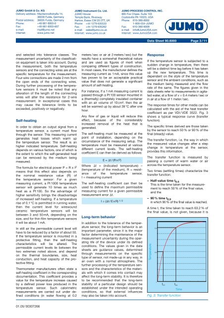
The response times for other media can be<br />
calculated with the aid of the heat transfer<br />
coefficient as per VDI / VDE 3522. Fig. 3<br />
shows a typical response curve (transfer<br />
function).<br />
The specific times derived are those taken<br />
by the sensor to reach 50 % or 90 % of the<br />
final (steady) value.<br />
The transfer function, i.e. the way in which<br />
the measured value changes after a step<br />
change in temperature at the sensor,<br />
provides this information.<br />
The transfer function is measured by<br />
passing a current of warm water or air<br />
across the temperature sensor.<br />
Two times (settling times) characterize the<br />
transfer function:<br />
– Half-value time t 0.5<br />
This is the time taken for the measurement<br />
to reach 50 % of the final value,<br />
and the<br />
– 90 % time t 0.9<br />
in which 90 % of the final value is reached.<br />
A time t, the time taken to reach 63.2 % of<br />
the final value, is not given, because it is<br />
Fig. 3: Transfer function<br />
01.05/ 00307266