Fatigue testing of energy storing prosthetic feet
Fatigue testing of energy storing prosthetic feet
Fatigue testing of energy storing prosthetic feet

Create successful ePaper yourself
Turn your PDF publications into a flip-book with our unique Google optimized e-Paper software.
182 S. L. Toh, J. C. H. Goh, P. H. Tan and T. E. Tay<br />
components and 10 Hz for assemblies <strong>of</strong> an all<br />
metallic nature. The applied load should be<br />
gradual, like a smooth sinusoidal waveform.<br />
These proposals were quite similar to those<br />
proposed by the Veteran Administration<br />
Prosthetic Centre (VAPC) during the ISPO<br />
conference, which included axial loads <strong>of</strong><br />
1020N and AP bending moments <strong>of</strong> 110 Nm.<br />
The VAPC (ISPO, 1978) also recommended<br />
for foot/ankle assembly, each sample should<br />
withstand 500.000 cycles under 150 lbf (667 N)<br />
load without failure and the permanent<br />
deformation should not exceed 1/8 inch<br />
(3.2 mm).<br />
Daher (1975) published the fatigue test<br />
results <strong>of</strong> various makes <strong>of</strong> SACH <strong>feet</strong> using a<br />
fatigue tester developed in his laboratory. The<br />
<strong>prosthetic</strong> foot was loaded to simulate the<br />
loading on the foot during normal walking by<br />
air pressure cycling in pneumatic cylinders. The<br />
loading sequence was controlled by time cams.<br />
One advantage <strong>of</strong> Daher's tester is the ability to<br />
test two <strong>feet</strong> simultaneously. Wevers and<br />
Durance (1987) developed a fatigue loading<br />
machine for lower limb prostheses following the<br />
standards proposed by ISPO. The machine uses<br />
a cam drive mechanism to mimic normal gait.<br />
Both the fatigue testers represent attempts by<br />
researchers to reproduce the loading on the<br />
<strong>prosthetic</strong> foot during normal walking. Despite<br />
considerable effort, time and cost spent to<br />
design such complex machines, it is <strong>of</strong>ten not<br />
quite possible to reproduce all the load<br />
components acting on the foot during normal<br />
walking. It is therefore proposed that a simple<br />
approach to fatigue <strong>testing</strong> <strong>of</strong> <strong>prosthetic</strong> <strong>feet</strong> be<br />
adopted by loading the <strong>prosthetic</strong> foot using<br />
only major load components, such as the<br />
vertical force and AP bending moment about<br />
the ankle.<br />
Design methodology<br />
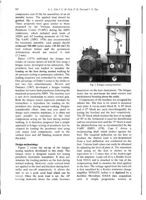
Figure 2 shows the set-up <strong>of</strong> the fatigue<br />
<strong>testing</strong> machine developed in this study. The<br />
fatigue tester is designed mainly for <strong>testing</strong><br />
<strong>prosthetic</strong> foot/ankle assemblies. It does not<br />
simulate the loading pattern on the foot during<br />
normal walking. However, cyclic vertical loads<br />
are applied to the heel and forefoot during heelstrike<br />
and toe-<strong>of</strong>f respectively. It allows the<br />
user to set a peak axial load which can be<br />
varied. Once the peak load is set, the AP<br />
bending moments about the ankle becomes<br />
Fig. 2. <strong>Fatigue</strong> <strong>testing</strong> machine.<br />
dependent on the foot dimensions. The fatigue<br />
tester has no provisions for axial torsion and<br />
medioJateral bending about the ankle.<br />
Components <strong>of</strong> the machine are designed for<br />
infinite life. The foot to be tested is mounted<br />
onto plate A via an ankle block B. A 30° block<br />
and a 15° block are used interchangeably for<br />
<strong>testing</strong> the forefoot and the heel respectively.<br />
The 30° block which inclines the foot at an angle<br />
<strong>of</strong> 30° to the horizontal is used for dorsiflexion<br />
and toe extension tests and the 15° block is used<br />
for plantarflexion test as recommended by the<br />
VAPC (ISPO, 1978). Cam C drives a<br />
reciprocating shaft which pushes against the<br />
foot. The required deflection on the foot to<br />
produce the desired load is pre-determined<br />
from a load deflection test conducted on the<br />
foot. Various load values can easily be obtained<br />
by adjusting the level <strong>of</strong> plate A. The maximum<br />
load acting on the foot is chosen to be<br />
equivalent to 1.5 times that <strong>of</strong> the bodyweight<br />
<strong>of</strong> the amputee. Load cell D is a Kistler Force<br />
Link 9321A and is attached to the top <strong>of</strong> the<br />
reciprocating shaft to monitor the load applied<br />
to the foot. The voltage signal from the load cell<br />
is first amplified by a Kistler miniature charge<br />
amplifier 5039A331 before it is digitised by a<br />
Keithley Metrabyte DAS-8 data acquisition<br />
card. A simple programme written in