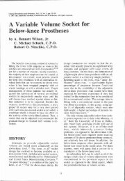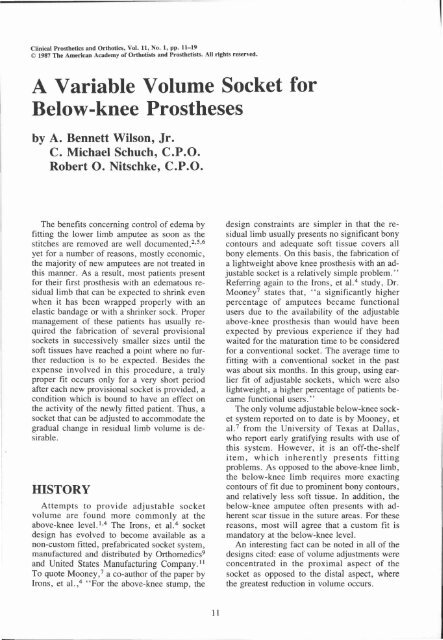
A Variable Volume Socket for Below-knee Prostheses
A Variable Volume Socket for Below-knee Prostheses
A Variable Volume Socket for Below-knee Prostheses

Create successful ePaper yourself
Turn your PDF publications into a flip-book with our unique Google optimized e-Paper software.
A <strong>Variable</strong> <strong>Volume</strong> <strong>Socket</strong> <strong>for</strong><br />
<strong>Below</strong>-<strong>knee</strong> <strong>Prostheses</strong><br />
by A. Bennett Wilson, Jr.<br />
C. Michael Schuch, C.P.O.<br />
Robert O. Nitschke, C.P.O.<br />
The benefits concerning control of edema by<br />
fitting the lower limb amputee as soon as the<br />
stitches are removed are well documented, 2 , 5 , 6<br />
yet <strong>for</strong> a number of reasons, mostly economic,<br />
the majority of new amputees are not treated in<br />
this manner. As a result, most patients present<br />
<strong>for</strong> their first prosthesis with an edematous residual<br />
limb that can be expected to shrink even<br />
when it has been wrapped properly with an<br />
elastic bandage or with a shrinker sock. Proper<br />
management of these patients has usually required<br />
the fabrication of several provisional<br />
sockets in successively smaller sizes until the<br />
soft tissues have reached a point where no further<br />
reduction is to be expected. Besides the<br />
expense involved in this procedure, a truly<br />
proper fit occurs only <strong>for</strong> a very short period<br />
after each new provisional socket is provided, a<br />
condition which is bound to have an effect on<br />
the activity of the newly fitted patient. Thus, a<br />
socket that can be adjusted to accommodate the<br />
gradual change in residual limb volume is desirable.<br />
HISTORY<br />
Attempts to provide adjustable socket<br />
volume are found more commonly at the<br />
above-<strong>knee</strong> level. 1 , 4 The Irons, et al. 4 socket<br />
design has evolved to become available as a<br />
non-custom fitted, prefabricated socket system,<br />
manufactured and distributed by Orthomedics 9<br />
and United States Manufacturing Company. 11<br />
To quote Mooney, 7<br />
a co-author of the paper by<br />
Irons, et al., 4<br />
"For the above-<strong>knee</strong> stump, the<br />
design constraints are simpler in that the residual<br />
limb usually presents no significant bony<br />
contours and adequate soft tissue covers all<br />
bony elements. On this basis, the fabrication of<br />
a lightweight above <strong>knee</strong> prosthesis with an adjustable<br />
socket is a relatively simple problem."<br />
Referring again to the Irons, et al. 4<br />
study, Dr.<br />
Mooney 7<br />
states that, "a significantly higher<br />
percentage of amputees became functional<br />
users due to the availability of the adjustable<br />
above-<strong>knee</strong> prosthesis than would have been<br />
expected by previous experience if they had<br />
waited <strong>for</strong> the maturation time to be considered<br />
<strong>for</strong> a conventional socket. The average time to<br />
fitting with a conventional socket in the past<br />
was about six months. In this group, using earlier<br />
fit of adjustable sockets, which were also<br />
lightweight, a higher percentage of patients became<br />
functional users."<br />
The only volume adjustable below-<strong>knee</strong> socket<br />
system reported on to date is by Mooney, et<br />
al. 7<br />
from the University of Texas at Dallas,<br />
who report early gratifying results with use of<br />
this system. However, it is an off-the-shelf<br />
item, which inherently presents fitting<br />
problems. As opposed to the above-<strong>knee</strong> limb,<br />
the below-<strong>knee</strong> limb requires more exacting<br />
contours of fit due to prominent bony contours,<br />
and relatively less soft tissue. In addition, the<br />
below-<strong>knee</strong> amputee often presents with adherent<br />
scar tissue in the suture areas. For these<br />
reasons, most will agree that a custom fit is<br />
mandatory at the below-<strong>knee</strong> level.<br />
An interesting fact can be noted in all of the<br />
designs cited: ease of volume adjustments were<br />
concentrated in the proximal aspect of the<br />
socket as opposed to the distal aspect, where<br />
the greatest reduction in volume occurs.
GOALS AND<br />
DESIGN CRITERIA<br />
After reviewing existing designs in which the<br />
volume of the socket can be adjusted, and considering<br />
the use of materials and techniques<br />
now available, a set of criteria was established<br />
<strong>for</strong> a custom fitted variable volume below-<strong>knee</strong><br />
socket as follows: 1) the socket would be<br />
custom fitted to the individual patient; 2) existing<br />
prosthetic molding, modification, and<br />
fabrication techniques would be used as appropriate;<br />
3) the volume would be controlled<br />
equally or selectively between proximal and<br />
distal parts of the residual limb; 4) normal prosthetic<br />
cosmesis would be possible and practical;<br />
and 5) the finished prosthesis would be light,<br />
but durable.<br />
The original, primary purpose of the project<br />
was to design a socket <strong>for</strong> use as a preparatory<br />
prosthesis, and thus avoid the need <strong>for</strong> several<br />
socket changes be<strong>for</strong>e stabilization occurs.<br />
However, it appears that the design that has resulted<br />
may also be very appropriate <strong>for</strong> use<br />
over extended periods where fluctuation in limb<br />
volume is difficult to control, or where the<br />
Figure 1. Exploded schematic view of the variable volume socket showing major components.
Figure 2. Schematic showing relationship of the major components of the variable volume socket.<br />
shear stresses normally encountered with<br />
present day socket designs present a problem.<br />
Because of the two-piece design (Figures 1<br />
and 2), it is possible to don and doff the prosthesis<br />
without subjecting the skin of the residual<br />
limb to shearing <strong>for</strong>ces, and thus should<br />
be considered when it is desirable to avoid<br />
shear on the limb. Additionally, the two-piece<br />
construction should add a measure of suspension<br />
if this element is considered in the individual<br />
design.<br />
We are confident that the concept is valid<br />
and useful. What follows here is, we hope, sufficient<br />
in<strong>for</strong>mation <strong>for</strong> an experienced prosthetist<br />
to try the concept. The materials and dimensions<br />
given are those that have been found<br />
to work in our still limited experience, but are<br />
by no means considered to be the best.<br />
Our original method <strong>for</strong> controlling volume,<br />
by use of two conventional hose clamps, is described<br />
here, because we have yet to locate a<br />
commercially available adjustment buckle that<br />
is suitable. We made some progress in designing<br />
a buckle especially <strong>for</strong> this purpose, but<br />
have not pursued the idea since the hose clamps<br />
can be made to work satisfactorily. However,<br />
there is probably a place <strong>for</strong> a more convenient<br />
method of controlling the circumferential dimensions.<br />
CASTING AND MODIFYING<br />
THE POSITIVE MODEL<br />
As stated in the design criteria, this socket<br />
system is intended to make use of existing prosthetic<br />
molding, modification, and fabrication<br />
techniques. We recommend use of the casting<br />
procedure described by Fillauer 3 in which an<br />
impression of the anterior portion of the limb<br />
is made first, using plaster splints to capture the<br />
bony definition be<strong>for</strong>e enclosing the remainder<br />
of the residual limb with plaster. Model modification<br />
should be carried out in normal function.<br />
We also recommend the use of a transparent<br />
diagnostic socket and algination procedure as<br />
described by Schuch and Lucy, 8<br />
be<strong>for</strong>e proceeding<br />
with pouring the final positive<br />
and fabrication of the socket.<br />
Fabrication<br />
of the <strong>Socket</strong><br />
model<br />
1) Place the positive model in a vise horizontally<br />
with the anterior section<br />
facing up.<br />
2) Over the positive model, <strong>for</strong>m a Pelite®<br />
liner <strong>for</strong> the anterior half of the<br />
socket. After heating a proper size<br />
sheet of Pelite®, a piece of latex<br />
rubber can be used to <strong>for</strong>m the Pelite®<br />
around the cast model.
Step 1.<br />
Steps 2 and 3.<br />
Steps 4 and 5.<br />
3) Trim the Pelite(tm) liner so that it extends<br />
posteriorly slightly past the midline,<br />
dividing the anterior-posterior<br />
halves of the model. Skive all edges<br />
that will be inside the socket. Remove<br />
thePelite(tm)liner from the cast in preparation<br />
<strong>for</strong> the next step.<br />
4) Rotate the model in the vise 180° so<br />
that the posterior surface is up.<br />
5) Using conventional drape molding<br />
techniques, vacuum <strong>for</strong>m a piece of 1/8<br />
inch polyethylene (or Surlyn®) around<br />
the model, posterior side up so the<br />
seam is on the anterior side.<br />
6) Trim the polyethylene to <strong>for</strong>m a posterior<br />
socket shell that extends anteriorly<br />
just past the midline and "underlaps"<br />
the Pelite® anterior liner by about<br />
3/8-1/2 inch. Again, skive all edges that<br />
will be inside the socket.
Step 6.<br />
7) With the Pelite® anterior liner and the<br />
polyethylene posterior shell in place on<br />
the model, pull a thin sheath of nylon<br />
over both to hold them in place.<br />
8) On the posterior aspect of the model,<br />
glue a 1/4 inch diameter rope to <strong>for</strong>m<br />
the cutout <strong>for</strong> the posterior volume<br />
control panel. Prepare <strong>for</strong> lamination in<br />
the usual manner. For use as a temporary<br />
design prosthesis, we use Otto<br />
Bock 10<br />
modular endoskeletal components<br />
and laminate the 4R42 component<br />
(socket adaptor with pyramid and<br />
lamination anchor) directly into the<br />
socket.<br />
9) Be<strong>for</strong>e beginning the lamination procedure,<br />
cut two polyethylene strips 1/16<br />
inch thick by 9 /16 inch wide by the circumference,<br />
plus 1/2 inch of the cast<br />
model at the levels shown.<br />
The strips are placed in the lamination layup<br />
and are removed after the lamination sets up to<br />
<strong>for</strong>m channels <strong>for</strong> the volume control straps.<br />
Layup <strong>for</strong> the lamination is as follows:<br />
1 layer of 1/2 oz. dacron felt<br />
1 nylon stockinette<br />
the 4R42 component (if used)<br />
I.P.O.S. 12<br />
glass matting over the lamination<br />
anchors of the 4R42 component and<br />
over the medial, lateral, and posterior<br />
aspects of the layup<br />
1 nylon stockinette; the two polyethylene<br />
strips cut earlier are placed at the appropriate<br />
levels;<br />
1 nylon stockinette<br />
2 nyglass stockinettes; laminate with 80:20<br />
mixtures of acrylic resin<br />
Step 7.
Step 8.<br />
10) When the laminate has set and cured,<br />
cut out the window over the rope and<br />
trim as shown.<br />
11) Using a pair of needle nose pliers, pull<br />
out the two polyethylene strips imbedded<br />
in the lamination. This leaves a<br />
clean, hidden track <strong>for</strong> guiding the pull<br />
of the control straps.<br />
12) Cut out an area about 1 1/2inches along<br />
each control strap track in the anteriorlateral<br />
area of the socket, to allow <strong>for</strong><br />
exposure of the adjustable part of the<br />
control strap.<br />
13) Make up control straps of 1/2 inch dacron<br />
tape and two to three inches of the<br />
hose clamps.<br />
14) Put the socket system back on the cast<br />
model <strong>for</strong> determination of the initial<br />
volume setting. Insert the dacron straps<br />
through the tracks and speedy rivet the<br />
hose clamp section so that the hex head<br />
of the clamp is exposed in the slots cut<br />
in step 12 above (Figure 3).<br />
15) Attach the pylon and foot and align in<br />
the conventional way (Figure 4).<br />
CLINICAL EXPERIENCE<br />
To date, seven variable volume below-<strong>knee</strong><br />
sockets have been fitted on six carefully chosen<br />
amputees. Five of these patients were new amputees<br />
and the variable volume socket prosthesis<br />
was their first prosthesis. One of these<br />
five had an extremely edematous limb due to a<br />
recent infection, and required two successive<br />
variable volume sockets be<strong>for</strong>e being fitted<br />
with a definitive conventional P.T.B, prosthesis.<br />
The remaining patient was a young amputee,<br />
three years post-amputation, who was<br />
having difficulty maintaining consistency in<br />
limb volume. The variable volume socket
Step 9.
Steps 10, 11,<br />
and 12.<br />
Figure 3. Photograph of laminated outer socket<br />
prior to mounting on adjustable leg. A foam<br />
block is shown here but this practice has been superceded<br />
by use of the Otto Bock 4R42 component<br />
which is laminated into the distal end of the<br />
outer socket.<br />
proved to be very useful in managing this patient.<br />
Evaluation was basically simple and subjective.<br />
The clinic team discussed and recorded<br />
any problems that arose with the socket design<br />
and documented that atrophy was accommodated<br />
by the variable volume socket. In all<br />
cases, maintenance of socket fit was made possible<br />
by decreasing socket volume as atrophy of<br />
the residue limb took place. At no point was<br />
com<strong>for</strong>t compromised by a reduction of socket<br />
volume.<br />
In addition to the patients fitted at the University<br />
of Virginia; trial fittings were made by<br />
Mr. Nitschke in the courses of development at<br />
Leimkuehler, Inc. in Cleveland, Ohio, American<br />
Orthotic and Prosthetic Laboratory, Inc. of<br />
Columbus, Ohio, and Rochester Orthopedic<br />
Laboratories, Inc. in Rochester, NY where we<br />
were given much help and encouragement. In<br />
addition, Karl Fillauer, CPO of Fillauer Orthopedic,<br />
Inc. in Knoxville, Tennessee has fit two<br />
patients and Robert Gooch, CP and John Michael,<br />
CPO of Duke University have fit one patient,<br />
all of whom are currently being followed.
SUMMARY AND<br />
CONCLUSION<br />
Rationale, design criteria, and fabrication<br />
techniques <strong>for</strong> an adjustable volume below<strong>knee</strong><br />
socket have been discussed and described.<br />
Successful fittings with the system have been<br />
noted. It is felt that this system can meet a need<br />
by providing new amputees with a durable,<br />
cosmetic, and reasonably long lasting preparatory<br />
prosthesis that accommodates the familiar<br />
problem of residual limb volume shrinkage.<br />
ACKNOWLEDGMENTS<br />
This work was made possible by support from the Veterans<br />
Administration Rehabilitation Research and Development<br />
Service. We are also grateful <strong>for</strong> the help and encouragement<br />
provided by Messrs. Jon Leimkuehler, CPO, Peter<br />
Ockenfels, CPO, Karl Fillauer, CPO, Carlton Fillauer,<br />
CPO, Robert Klebba, Robert Gooch, CP, John Michael,<br />
CPO, and Dr. Frank Clippinger.<br />
AUTHORS<br />
A. Bennett Wilson, Jr. and Michael Schuch are with the<br />
Department of Orthopedics and Rehabilitation at the University<br />
of Virginia.<br />
Robert Nitschke is a consultant and lives in Rochester,<br />
NY.<br />
Figure 4. <strong>Variable</strong> volume socket mounted<br />
on an adjustable leg.<br />
REFERENCES<br />
1<br />
Brownsey, ZZ; Fillauer, ZZ: "Temporary Prosthesis<br />
with Adjustable <strong>Socket</strong>," Physical Therapy, 47:12:December,<br />
1967, pp. 1129-1131<br />
2<br />
Fernie, Geoff, R. and Pamela J. Holiday, "<strong>Volume</strong><br />
Fluctuations in the Residual Limbs of Lower Limb Amputees,"<br />
Archives of Physical Medicine and Rehabilitation,<br />
63:4:April, 1982, pp. 162-165.<br />
3<br />
Fillauer, Carlton, "A Patella-Tendon-Bearing <strong>Socket</strong><br />
with a Detachable Media Brim," Orthotics and Prosthetics,<br />
25:4:December 1971, pp. 25<br />
4<br />
Irons, G., V. Mooney, S. Putnam, M. Quigley, "A<br />
Lightweight Above Knee Prosthesis With an Adjustable<br />
<strong>Socket</strong>, Orthotics and Prosthetics, 31:1:March 1977, pp.<br />
3-15.<br />
5<br />
Malone, J. et al, "Rehabilitation <strong>for</strong> Lower Extremity<br />
Amputation," Archives of Surgery, 116:1:January 1981,<br />
pp. 93-98.<br />
6<br />
Malone, J. et al., "Therapeutic and Economic Impact<br />
of a Moderate Amputation Program," Annals of Surgery,<br />
189:6:June 1979, pp. 798-802.<br />
7<br />
Mooney, V., B. McClellan, D. Cummings, P. Smith,<br />
"Early Fitting of the <strong>Below</strong> Knee Amputee," Orthopedics,<br />
8:2:February 1985, pp. 199-202.<br />
8<br />
Schuch, C. Michael, and Tony Lucy, "Experience<br />
with the Use of Alginate in Transparent Diagnostic <strong>Below</strong>-<br />
Knee <strong>Socket</strong>s," Clinical Prosthetics and Orthotics,<br />
10:3:Summer 1986, pp. 101-104.<br />
9<br />
Orthomedics, Inc., 2950 East Imperial Highway, Brea,<br />
Cali<strong>for</strong>nia 92621.<br />
10<br />
Otto Bock Orthopedic Industry, Inc., 4130 Highway<br />
55, Minneapolis, Minnesota 55422.<br />
11<br />
United States Manufacturing Company, 180 North<br />
San Gabriel Blvd., Pasadena, Cali<strong>for</strong>nia 91107.<br />
12<br />
I.P.O.S., U.S.A., 155 Portage Road, Lewiston, New<br />
York 14092.