A Shortened 40-Meter Four-Element Sloping Dipole Array
A Shortened 40-Meter Four-Element Sloping Dipole Array
A Shortened 40-Meter Four-Element Sloping Dipole Array

You also want an ePaper? Increase the reach of your titles
YUMPU automatically turns print PDFs into web optimized ePapers that Google loves.
l = physical length of the stub<br />
λ = wavelength<br />
k = velocity factor<br />
For RG-8 or RG-58 coax k is about 0,66 so l is 36 feet. You can determine the<br />
velocity factor for other cables from antenna handbooks. When using cables like<br />
inexpensive TV coax where no reliable velocity factor value is available, you have to<br />
measure the velocity factor of the cable. This can be done with a simple dip-meter or<br />
an SWR-analyzer.<br />
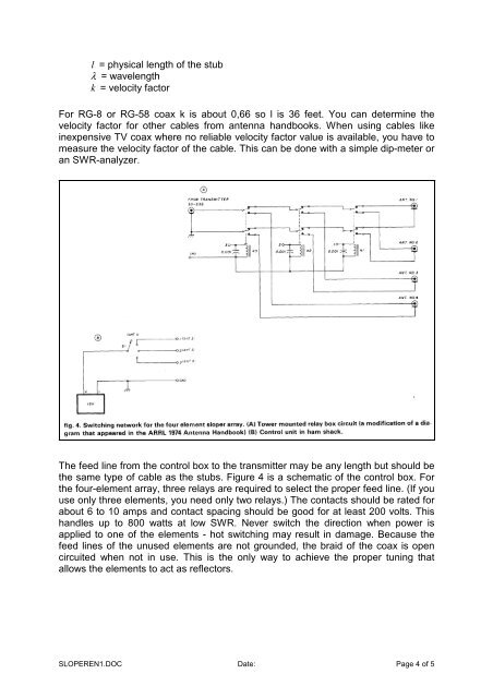
The feed line from the control box to the transmitter may be any length but should be<br />
the same type of cable as the stubs. Figure 4 is a schematic of the control box. For<br />
the four-element array, three relays are required to select the proper feed line. (If you<br />
use only three elements, you need only two relays.) The contacts should be rated for<br />
about 6 to 10 amps and contact spacing should be good for at least 200 volts. This<br />
handles up to 800 watts at low SWR. Never switch the direction when power is<br />
applied to one of the elements - hot switching may result in damage. Because the<br />
feed lines of the unused elements are not grounded, the braid of the coax is open<br />
circuited when not in use. This is the only way to achieve the proper tuning that<br />
allows the elements to act as reflectors.<br />
SLOPEREN1.DOC Date: Page 4 of 5