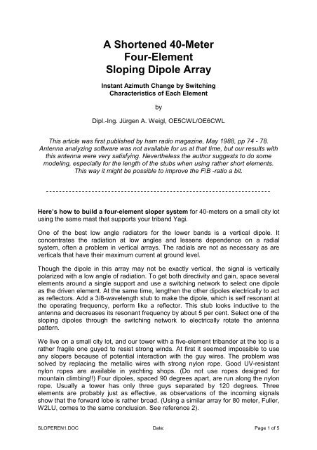
A Shortened 40-Meter Four-Element Sloping Dipole Array
A Shortened 40-Meter Four-Element Sloping Dipole Array
A Shortened 40-Meter Four-Element Sloping Dipole Array

Create successful ePaper yourself
Turn your PDF publications into a flip-book with our unique Google optimized e-Paper software.
A <strong>Shortened</strong> <strong>40</strong>-<strong>Meter</strong><br />
<strong>Four</strong>-<strong>Element</strong><br />
<strong>Sloping</strong> <strong>Dipole</strong> <strong>Array</strong><br />
Instant Azimuth Change by Switching<br />
Characteristics of Each <strong>Element</strong><br />
by<br />
Dipl.-Ing. Jürgen A. Weigl, OE5CWL/OE6CWL<br />
This article was first published by ham radio magazine, May 1988, pp 74 - 78.<br />
Antenna analyzing software was not available for us at that time, but our results with<br />
this antenna were very satisfying. Nevertheless the author suggests to do some<br />
modeling, especially for the length of the stubs when using rather short elements.<br />
This way it might be possible to improve the F/B -ratio a bit.<br />
- - - - - - - - - - - - - - - - - - - - - - - - - - - - - - - - - - - - - - - - - - - - - - - - - - - - - - - - - - - - - - - - - - - - -<br />
Here’s how to build a four-element sloper system for <strong>40</strong>-meters on a small city lot<br />
using the same mast that supports your triband Yagi.<br />
One of the best low angle radiators for the lower bands is a vertical dipole. It<br />
concentrates the radiation at low angles and lessens dependence on a radial<br />
system, often a problem in vertical arrays. The radials are not as necessary as are<br />
verticals that have their maximum current at ground level.<br />
Though the dipole in this array may not be exactly vertical, the signal is vertically<br />
polarized with a low angle of radiation. To get both directivity and gain, space several<br />
elements around a single support and use a switching network to select one dipole<br />
as the driven element. At the same time, lengthen the other dipoles electrically to act<br />
as reflectors. Add a 3/8-wavelength stub to make the dipole, which is self resonant at<br />
the operating frequency, perform like a reflector. This stub looks inductive to the<br />
antenna and decreases its resonant frequency by about 5 per cent. Select one of the<br />
sloping dipoles through the switching network to electrically rotate the antenna<br />
pattern.<br />
We live on a small city lot, and our tower with a five-element tribander at the top is a<br />
rather fragile one guyed to resist strong winds. At first it seemed impossible to use<br />
any slopers because of potential interaction with the guy wires. The problem was<br />
solved by replacing the metallic wires with strong nylon rope. Good UV-resistant<br />
nylon ropes are available in yachting shops. (Do not use ropes designed for<br />
mountain climbing!!) <strong>Four</strong> dipoles, spaced 90 degrees apart, are run along the nylon<br />
rope. Usually a tower has only three guys separated by 120 degrees. Three<br />
elements are probably just as effective, as observations of the incoming signals<br />
show that the forward lobe is rather broad. (Using a similar array for 80 meter, Fuller,<br />
W2LU, comes to the same conclusion. See reference 2).<br />
SLOPEREN1.DOC Date: Page 1 of 5
<strong>Shortened</strong> elements<br />
The tower is about 56 feet (17 meters) high, and two of the four guys are fastened to<br />
the house about 6 feet above ground - a serious problem. Consequently, with the<br />
maximum possible element length, shortened dipoles had to be used. My design,<br />
shown in fig.1, uses a 4,5 µH inductance in each leg. A coil 12,5 turns, 1,5 inches in<br />
diameter and 1,4 inches long, provides the value of inductance.<br />
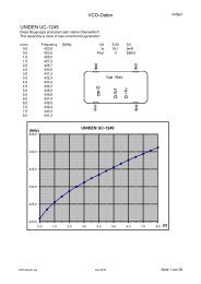
<strong>Shortened</strong> <strong>40</strong> m dipole SWR vs. frequency<br />
4<br />
3,5<br />
3<br />
SWR<br />
2,5<br />
2<br />
1,5<br />
1<br />
6,8 6,9 7 7,1 7,2 7,3<br />
Frequency [MHz]<br />
Fig.2. SWR of the shortened <strong>40</strong> m elements. Antenna was tuned<br />
for lowest SWR over the European segment of the band.<br />
Note the SWR is less than 1:2,0 over 200 kHz of band width.<br />
SLOPEREN1.DOC Date: Page 2 of 5
Tuning of each shortened dipole is critical. They were tuned in a horizontal position<br />
about 13 feet above ground. As each antenna was put on the tower, the resonant<br />
frequency changed. I spent quite some time tuning the elements for resonance by<br />
connecting one element through an SWR bridge to the transmitter, while the other<br />
elements were disconnected. Though not grounded, they must be there with the<br />
required open feed line as there is always some interaction between the elements.<br />
Each element has to be tuned for the same resonant frequency and must show the<br />
same SWR across the band in order to switch direction without retuning the<br />
transmitter or linear. Figure 2 shows a plot of the SWR for one of the elements. The<br />
resonance is in the CW portion of the band. To tune for a higher frequency, just<br />
shorten the antenna.<br />
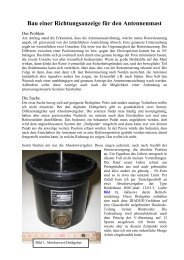
Attaching the dipoles to the guy wires<br />
Each element should be attached to the guy at only three points. The guy line<br />
passes through the tube of the upper loading coil, through a small loop fastened to<br />
the center insulator, and then through the tube of the lower loading coil. The upper<br />
end of the antenna is suspended from a 20-inch rope. Be sure the antenna moves<br />
along the guy freely or it may break in strong winds.<br />
Controlling the direction<br />
Figure 3 shows the basic antenna layout. The feed lines (3/8 wavelength long), which<br />
connect the various elements to the control box, are a vital part or the system.<br />
Remember that you have to consider the velocity factor of your coax cable. Equation<br />
1 gives you the physical length for cutting your feed lines.<br />
l<br />
= 0, 375 × λ × k Eq. (1)<br />
SLOPEREN1.DOC Date: Page 3 of 5
l = physical length of the stub<br />
λ = wavelength<br />
k = velocity factor<br />
For RG-8 or RG-58 coax k is about 0,66 so l is 36 feet. You can determine the<br />
velocity factor for other cables from antenna handbooks. When using cables like<br />
inexpensive TV coax where no reliable velocity factor value is available, you have to<br />
measure the velocity factor of the cable. This can be done with a simple dip-meter or<br />
an SWR-analyzer.<br />
The feed line from the control box to the transmitter may be any length but should be<br />
the same type of cable as the stubs. Figure 4 is a schematic of the control box. For<br />
the four-element array, three relays are required to select the proper feed line. (If you<br />
use only three elements, you need only two relays.) The contacts should be rated for<br />
about 6 to 10 amps and contact spacing should be good for at least 200 volts. This<br />
handles up to 800 watts at low SWR. Never switch the direction when power is<br />
applied to one of the elements - hot switching may result in damage. Because the<br />
feed lines of the unused elements are not grounded, the braid of the coax is open<br />
circuited when not in use. This is the only way to achieve the proper tuning that<br />
allows the elements to act as reflectors.<br />
SLOPEREN1.DOC Date: Page 4 of 5
Other bands<br />
I hope this article will encourage you to build this or a similar array. If space permits,<br />
use full size elements. If a shortened dipole is needed, design data is available for<br />
other frequencies (e.g. Ref. 1). An 80-meter dipole for use at 3,8 MHz is described in<br />
fig. 5.<br />
With an antenna tower only 78 feet high you will be able to join other amateurs with a<br />
directive 80-meter antenna. The bandwidth for such an antenna will be small, but if<br />
you use low-loss coils the antenna should be quite effective and possibly achieve 4<br />
dB of gain.<br />
References:<br />
1. The ARRL Antenna Book, Newington, CT, USA<br />
2. Fuller, Eugene B., W2LU, „<strong>Sloping</strong> 80-meter array“, ham radio magazine, May<br />
1979, page 70<br />
Note: The author has developed a multi band directive antenna system similar to the<br />
one described above. By using multi band dipoles (e.g. W3DZZ) it is possible to<br />
cover several bands (e.g. <strong>40</strong> and 80 meters) with one directive antenna. For this<br />
invention a patent has been granted. The design of the stubs in a multi band array is<br />
different to the system described above. If you would like to have more information,<br />
please feel free to contact the author (weigl+info@nextra.at).<br />
SLOPEREN1.DOC Date: Page 5 of 5