English - OFI Testing Equipment, Inc.
English - OFI Testing Equipment, Inc.
English - OFI Testing Equipment, Inc.

You also want an ePaper? Increase the reach of your titles
YUMPU automatically turns print PDFs into web optimized ePapers that Google loves.
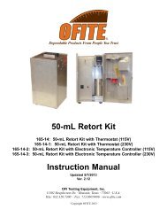
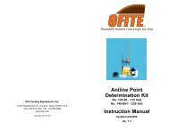
Pressurized Fluid Density Scale<br />
Part #: 100-70<br />
Instruction Manual<br />
Updated 3/12/2013<br />
Ver. 1.6<br />
<strong>OFI</strong> <strong>Testing</strong> <strong>Equipment</strong>, <strong>Inc</strong>.<br />
11302 Steeplecrest Dr. · Houston, Texas · 77065 · U.S.A.<br />
Tele: 832.320.7300 · Fax: 713.880.9886 · www.ofite.com<br />
©<br />
Copyright <strong>OFI</strong>TE 2013
Table of<br />
Contents<br />
Intro....................................................................................................2<br />
Description........................................................................................2<br />
Components......................................................................................3<br />
Operation ..........................................................................................4<br />
Calibration.........................................................................................7<br />
Maintenance......................................................................................9<br />
<strong>OFI</strong>TE, 11302 Steeplecrest Dr., Houston, TX 77065 USA / Tel: 832-320-7300 / Fax: 713-880-9886 / www.ofite.com 1
Intro<br />
Drilling fluids and cements often have a considerable amount of air<br />
entrained or trapped within the fluid that may give erroneous results when<br />
determining fluid density using conventional equipment. This air volume<br />
may be decreased to a negligible quantity by pressurizing the sample cup,<br />
which will then give more accurate density readings of the fluid itself.<br />
Description<br />
The <strong>OFI</strong>TE Pressurized Fluid Density Scale is similar to a standard mud<br />
balance. A sample cup of known volume is balanced by a fixed counterweight<br />
at the opposite end of a balance beam. A sliding weight rider<br />
moves along the graduated scale and a level bubble on the beam indicates<br />
when the system is in balance. The position of the rider on the graduated<br />
scale indicates the density of the sample.<br />
In the center of the lid is a check valve that allows a one-way flow of test<br />
fluid into the sample cup. A plunger attaches to the check valve and<br />
applies pressure to the sample cup. When the pressure in the sample cup<br />
increases, the check valve automatically closes, sealing off the pressure<br />
inside. A cap holds the lid in place.<br />
The balance beam has four graduated scales:<br />
- 52 - 164 lb / ft 3<br />
- 6.9 - 21.9 ppg<br />
- .83 - 2.63 specific gravity<br />
- 360 - 1130 PSI / 1000 ft<br />
<strong>OFI</strong>TE, 11302 Steeplecrest Dr., Houston, TX 77065 USA / Tel: 832-320-7300 / Fax: 713-880-9886 / www.ofite.com 2
Components<br />
#100-29 Level Bubble Vial<br />
#100-56 Lead Shot<br />
#100-60-09 Check Valve<br />
#100-60-24 Retaining Ring for Check Valve<br />
#100-70-01 Sample Cup and Mud Arm Assembly<br />
#100-70-02 Lid<br />
#100-70-03 Cap<br />
#100-70-04 Rider<br />
#100-70-05 Shot Well<br />
#100-70-06 O-ring for Lid<br />
#100-70-07 Plunger Assembly<br />
#100-60-13 Packing Cup, Plastic<br />
#100-70-010 Knob<br />
#100-70-11 Piston Rod<br />
#100-70-13 Compression Cylinder<br />
#100-70-14 Lower Plunger Cap<br />
#100-70-15 Upper Plunger Cap<br />
#170-07 O-ring<br />
#100-70-08 Carrying Case<br />
#100-70-24 Base<br />
#100-70-25 Cover for Level Bubble Vial<br />
#115-32 Knife Edge<br />
#142-54 O-ring for Check Valve Nozzle<br />
#142-56 O-ring for Check Valve<br />
Optional:<br />
#100-70-101 Calibration Fixture<br />
#100-70-SP Spare Parts Kit<br />
#100-60-24 Retaining Ring, Qty: 2<br />
#100-70-06 O-ring for Lid, Qty: 6<br />
#142-54 O-ring for Check Valve Nozzle, Qty: 6<br />
#142-56 O-ring for Check Valve, Qty: 4<br />
#100-60-13 Packing Cup for Plunger Assembly, Qty: 3<br />
#170-07 O-ring for Plunger Assembly, Qty: 4<br />
Check Valve (#100-60-09)<br />
Lid (#100-70-02)<br />
O-ring (#142-54)<br />
Retaining Ring<br />
(#100-60-24)<br />
O-ring (#142-56)<br />
O-ring (#100-70-06)<br />
<strong>OFI</strong>TE, 11302 Steeplecrest Dr., Houston, TX 77065 USA / Tel: 832-320-7300 / Fax: 713-880-9886 / www.ofite.com 3
Operation<br />
1. Fill the sample cup to within ¼" of the top with fluid to be tested.<br />
2. Push the check valve down to open it.<br />
3. Place the lid on the sample cup and press it down slowly.<br />
<br />
Tip<br />
!<br />
Important<br />
As you press the lid into the sample cup, fluid should leak out of the<br />
check valve. If no fluid leaks from the check valve, remove the lid and<br />
add more fluid.<br />
Be careful when pressing the lid into the sample cup. Test fluid may<br />
spray out of the check valve. Always press the lid slowly and remember<br />
to wear protective eyewear.<br />
4. Place the cap over the lid and screw it in place.<br />
Cap<br />
Check Valve<br />
Lid<br />
Sample Cup<br />
Level Bubble<br />
Arm<br />
5. Push the plunger all the way into the plunger cylinder.<br />
Plunger Cylinder<br />
Plunger<br />
<strong>OFI</strong>TE, 11302 Steeplecrest Dr., Houston, TX 77065 USA / Tel: 832-320-7300 / Fax: 713-880-9886 / www.ofite.com 4
6. Place the end of the plunger cylinder into the test fluid and pull the<br />
plunger all the way out. This will draw test fluid into the plunger cylinder.<br />
7. Place the end of the plunger cylinder over the top of the check valve.<br />
8. With one hand, press down on the plunger cylinder to keep the check<br />
valve open. With the other hand, press down on the plunger to apply<br />
approximately 50 lb of force.<br />
Plunger<br />
Check<br />
Valve<br />
Check Valve Open<br />
Check Valve Closed<br />
9. While continuing to apply 50 lb of force to the plunger, slowly raise the<br />
plunger. This will allow the check valve to pop up, sealing off the pressure<br />
inside the sample cup.<br />
10. When the check valve has risen about ¼", stop applying force to the<br />
plunger and remove it from the valve.<br />
<strong>OFI</strong>TE, 11302 Steeplecrest Dr., Houston, TX 77065 USA / Tel: 832-320-7300 / Fax: 713-880-9886 / www.ofite.com 5
11. Clean and dry the outside of the sample cup and balance arm.<br />
12. Balance the instrument with the knife edge resting on the base.<br />
13. Move the rider back and forth until the arm is balanced. When the arm<br />
is balanced, the bubble in the level will be between the two lines.<br />
14. Read the density from the scale printed on the arm.<br />
Knife Edge<br />
Base<br />
Rider<br />
<strong>OFI</strong>TE, 11302 Steeplecrest Dr., Houston, TX 77065 USA / Tel: 832-320-7300 / Fax: 713-880-9886 / www.ofite.com 6
Calibration<br />
Basic Calibration<br />
The Pressurized Fluid Density Scales are calibrated at the factory prior to<br />
shipment. Use the following procedure to confirm the unit is still in calibration.<br />
1. Clean the entire instrument.<br />
2. Fill the sample cup with clean, fresh water and pressurize it.<br />
3. Balance the instrument with the knife edge resting on the base.<br />
4. Move the rider to 1.00 on the specific gravity scale.<br />
5. Observe the level bubble. If the bubble is off center, the instrument is<br />
out of balance.<br />
6. Unscrew and remove the shot well.<br />
7. If the bubble is closer to the sample cup, remove lead shot from the<br />
shot well. If the bubble is closer to the shot well, add lead shot.<br />
8. Screw the shot well back into the arm.<br />
9. Repeat steps 3 through 8 until the level bubble is centered.<br />
Sample Cup Rider Shot Well<br />
<strong>OFI</strong>TE, 11302 Steeplecrest Dr., Houston, TX 77065 USA / Tel: 832-320-7300 / Fax: 713-880-9886 / www.ofite.com 7
Re-qualification Calibration:<br />
If the balance is ever damaged or any non-consumable parts are replaced<br />
(lid, cap, check valve, rider, or shot well), a more thorough calibration will<br />
be necessary.<br />
1. Perform the basic calibration described on page 7.<br />
2. Remove the water from the sample cup and thoroughly clean and dry<br />
the instrument.<br />
3. Place the lid and cap back on the sample cup.<br />
4. Attach the calibration fixture (#100-70-101) to the sample cup.<br />
Calibration Fixture<br />
5. Adjust the weights on the fixture until the unit balances at 1.00 specific<br />
gravity. Lock the weights so they do not move.<br />
6. Fill the sample cup with clean, fresh water and pressurize it.<br />
7. Perform another basic calibration as described on page 7. The unit<br />
should balance at 2.00 specific gravity.<br />
<strong>OFI</strong>TE, 11302 Steeplecrest Dr., Houston, TX 77065 USA / Tel: 832-320-7300 / Fax: 713-880-9886 / www.ofite.com 8
Maintenance<br />
1. Before every test, inspect the o-ring on the lid and the two o-rings on the<br />
check valve. Make sure they are not brittle, chiped, torn, or stretched. If<br />
any o-ring shows signs of wear, replace it with a new o-ring.<br />
2. After each test, thoroughly clean the instrument, including the plunger,<br />
with water and an appropriate solvent. Make sure no test fluid (especially<br />
cement) remains on any surfaces. Repeatedly fill and purge the<br />
plunger assembly to remove any test fluid.<br />
3. Always store the instrument clean and dry in the provided carrying<br />
case.<br />
<strong>OFI</strong>TE, 11302 Steeplecrest Dr., Houston, TX 77065 USA / Tel: 832-320-7300 / Fax: 713-880-9886 / www.ofite.com 9