BICSI News Magazine - OFS
BICSI News Magazine - OFS
BICSI News Magazine - OFS

You also want an ePaper? Increase the reach of your titles
YUMPU automatically turns print PDFs into web optimized ePapers that Google loves.
<strong>BICSI</strong>news<br />
m a g a z i n e<br />
may/june 2010<br />
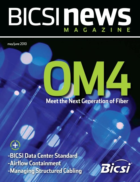
OM4<br />
Meet the Next Generation of Fiber<br />
-<strong>BICSI</strong> Data Center Standard<br />
-Airflow Containment<br />
-Managing Structured Cabling
cover story<br />
OM4<br />
Meet the Next Generation of Fiber<br />
by Tony Irujo<br />
Electronic reprint with permission from <strong>BICSI</strong> <strong>News</strong> <strong>Magazine</strong>-May/June 2010 Issue
As the demand for bandwidth in enterprise applications<br />
like data centers continues to boom, new transmission<br />
media must be continually developed to meet end user<br />
requirements. The latest in optical transmission media for<br />
the enterprise is called OM4 optical fiber.<br />
&technology<br />
innovation<br />
OM4 is a 50 micrometer (μm) laseroptimized<br />
multimode optical fiber with<br />
extended bandwidth. It will be used to<br />
enhance the system cost benefits enabled<br />
by 850 nanometer (nm) vertical cavity<br />
surface emitting lasers (VCSELs) for<br />
existing 1 and 10 gigabit per second (Gb/s)<br />
applications as well as future 40 and 100<br />
Gb/s systems. Supporting Ethernet, Fibre<br />
Channel and Optical Internetworking<br />
Forum (OIF) applications, OM4 fiber<br />
allows extended reach upward of 550<br />
meters (m [1804 feet (ft)]) at 10 Gb/s for<br />
ultralong building backbones and medium<br />
length campus backbones. It offers an<br />
effective modal bandwidth (EMB) of 4700<br />
megahertz kilometer (MHz•km), more<br />
than double the IEEE requirement for<br />
10 Gb/s 300 m (984 ft) support.<br />
To help you use this advanced optical<br />
fiber to its greatest advantage, this article<br />
describes the technology behind OM4,<br />
highlights the key differences with other<br />
optical fiber types and explains how<br />
its high bandwidth is ensured through<br />
stringent measurement methods.<br />
Multimode Fundamentals<br />
Compared with singlemode optical<br />
fibers, multimode optical fibers have<br />
larger cores that, as their name implies,<br />
guide multiple “modes” or rays of light<br />
simultaneously (see Figure 1). Modes that<br />
travel at the outside edge of the core have<br />
a longer distance to go than modes that<br />
travel near the center of the core.<br />
The core’s graded index profile is<br />
designed to slow down modes that have<br />
a shorter distance to travel so that all<br />
modes arrive at the end of the fiber as<br />
close in time as possible. This minimizes<br />
modal dispersion, also known as differential<br />
mode delay (DMD), and maximizes bandwidth,<br />
which is the amount of information<br />
that can travel through the fiber per unit<br />
of time.<br />
In addition to their large core,<br />
multimode optical fibers have a large<br />
numerical aperture (NA), the maximum<br />
angle at which an optical fiber can accept<br />
the light that will be transmitted through<br />
it. This allows them to work with relatively<br />
low-cost optical components and light<br />
sources such as light-emitting diodes (LEDs)<br />
and VCSELs.<br />
OM4 fiber is also<br />
available in a bendoptimized<br />
design.<br />
These fibers offer all<br />
the advantages of highbandwidth<br />
multimode<br />
fiber with the added<br />
advantage of lower<br />
bend sensitivity.<br />
Tony Irujo is a sales engineer<br />
for <strong>OFS</strong> where he provides<br />
technical sales and marketing<br />
support for multimode and<br />
singlemode optical fiber. He<br />
has 25 years experience in<br />
optical fiber manufacturing,<br />
testing and applications and<br />
can be reached at tirujo@<br />
ofsoptics.com.<br />
Electronic reprint with permission from <strong>BICSI</strong> <strong>News</strong> <strong>Magazine</strong>-May/June 2010 Issue
Multimode Options<br />
Multimode products are identified<br />
by the optical multimode (OM) designation<br />
as outlined in the ISO/IEC<br />
11801 international cabling standard<br />
(see Table 1).<br />
OM4 fiber is the latest development<br />
in this series. It is especially<br />
well suited for shorter reach data<br />
center and high-performance<br />
computing applications where optical<br />
loss budgets are rather tight at 10 Gb/s<br />
(and are expected to get even tighter<br />
at 40 Gb/s and 100 Gb/s). The high<br />
bandwidth provided when OM4 fiber is<br />
deployed at less than its rated distance<br />
offers extra headroom for channel<br />
insertion loss.<br />
OM4 is backward compatible<br />
with applications calling for overfilled<br />
launch (OFL) bandwidth of at least 500<br />
MHz•km at 1300 nm (e.g., FDDI, IEEE<br />
100BASE-FX, 1000BASE-LX, 10GBASE-<br />
LX4, 10GBASE-LRM).<br />
OM4 fiber is also available in a<br />
bend-optimized design. These fibers<br />
offer all the advantages of highbandwidth<br />
multimode fiber with<br />
the added advantage of lower bend<br />
sensitivity. Whereas traditional 50 µm<br />
multimode fibers can be sensitive to<br />
tight bends, bend-optimized fibers<br />
offer extremely low bending loss at<br />
both 850 nm and 1300 nm. They<br />
can be bent down to a radius of 7.5<br />
millimeters (mm), which is almost<br />
1/3 inch (in), with less than 0.2 decibel<br />
(dB) added loss at 850 nm. At a<br />
15 mm radius (about 1/2 in), the<br />
added loss is less than 0.1 dB. This is<br />
up to a 10x improvement in bend<br />
loss compared with traditional multimode<br />
fiber.<br />
What Makes OM4 Different?<br />
Like OM3 multimode optical<br />
fiber, OM4 fiber is considered to be<br />
laser-optimized, or optimized for<br />
use with VCSEL light sources. OM3<br />
and OM4 fibers are designed and<br />
manufactured in such a way as to get<br />
the most performance out of VCSELs<br />
Figure 1: Multimode fibers have larger cores that guide multiple modes, or rays of light, simultaneously.<br />
Modal dispersion causes pulse spreading, which limits bandwidth.<br />
Designation Bandwidth Transmission (nm) Product Type<br />
OM1 200/500 MHz•km 850/1300 62.5/125 µm fiber<br />
overfilled launch (OFL)<br />
OM2 500/500 MHz•km (OFL) 850/1300 50/125 µm fiber<br />
OM3 2000 MHz•km EMB 850 Laser-optimized<br />
50 µm fiber<br />
compared with LEDs. That is why laseroptimized<br />
fibers are specified using<br />
laser bandwidth, or EMB.<br />
Although compatible with VCSELs,<br />
OM2 fiber is not considered laser<br />
optimized. OM2 fiber’s intended use<br />
is with LED sources at speeds of 10 or<br />
100 megabits per second (Mb/s), or<br />
for shorter reach 1 Gb/s networks. You<br />
can use OM2 fiber with VCSELs, but<br />
its performance is limit (269 ft) at 10<br />
Table 1: ISO/IEC 11801 OM Designations<br />
Figure 2: A refractive index profile that<br />
is optimized for shape, curvature and<br />
smoothness maximizes bandwidth.<br />
Gb/s, compared with OM4 fiber’s reach<br />
of over 1000 m (3281 ft) at 1 Gb/s and<br />
550 m (1804 ft) at 10 Gb/s.<br />
As discussed, the speed at which<br />
each mode travels down a multimode<br />
fiber’s core depends on its refractive<br />
index, which is governed by the<br />
amount of chemical dopant<br />
germanium at that location in the core.<br />
Because modes traveling down the<br />
center of the core have shorter distance<br />
Electronic reprint with permission from <strong>BICSI</strong> <strong>News</strong> <strong>Magazine</strong>-May/June 2010 Issue
to travel than those traveling along<br />
the edge, the refractive index profile<br />
in a multimode fiber must be graded<br />
in a parabolic manner across the core.<br />
This slows down the modes that have a<br />
shorter distance to travel, equalizing the<br />
arrival time of all the modes.<br />
The better the modes are equalized,<br />
the higher the bandwidth of the fiber.<br />
Mode equalization depends on how<br />
well the graded index profile is<br />
constructed during fiber manufacturing.<br />
The more precise the refractive index<br />
profile is in terms of shape, curvature<br />
and smoothness (free of dips, spikes or<br />
defects), the better the modes will be<br />
equalized (see Figure 2).<br />
OM4 fiber, with its higher<br />
bandwidth, has an extremely precise<br />
refractive index profile—virtually free<br />
of perturbations or defects. In order<br />
to make such a precise fiber, one<br />
needs to use a preform manufacturing<br />
process that has exceptional control<br />
over the amount of germanium that is<br />
incorporated at particular submicron<br />
positions within the fiber’s core. An<br />
example of such a process that lends<br />
itself to this level of control is the<br />
patented modified chemical vapor<br />
deposition (MCVD) process, where<br />
each layer of the core is deposited and<br />
sintered individually, providing the<br />
utmost in refractive index precision<br />
and uniformity.<br />
The OM4 Fiber Standard<br />
Two standards define the use of<br />
OM4 fiber in high-speed networks—<br />
TIA-492AAAD, which contains the<br />
OM4 fiber performance specifications,<br />
and the IEC 60793-2-10 international<br />
standard, which provides equivalent<br />
OM4 specifications under fiber type<br />
A1a.3.<br />
ISO/IEC 11801 will add OM4<br />
fiber as an industry-recognized fiber<br />
type, and IEEE 802.3ba for 40 Gigabit<br />
Ethernet (GbE) and 100 GbE will<br />
include OM4 fiber as an option that<br />
provides a reach of 150 m (492 ft),<br />
which is 50 percent greater than OM3.<br />
Figure 3: Different VCELS fill a different set of modes in each fiber,<br />
which can affect pulse spreading (bandwidth).<br />
There was discussion and debate<br />
within the standards groups about a<br />
minimum OFL bandwidth requirement<br />
at 850 nm. Although current<br />
applications primarily use 850 nm<br />
VCSEL lasers with fibers that are<br />
specified to a minimum EMB, there<br />
was good reason to also establish a<br />
minimum 850 nm OFL bandwidth<br />
specification. It has been shown that<br />
fibers with higher OFL bandwidth will<br />
perform better with VCSELs that launch<br />
more power into outer modes. That is<br />
why the existing OM3 fiber standards<br />
require a minimum 1500 MHz•km OFL<br />
bandwidth at 850 nm.<br />
For OM4, the standards group<br />
strongly recommended at least 3500<br />
MHz•km OFL bandwidth in order<br />
to ensure the utmost performance<br />
and reliability. Ultimately, that is the<br />
specification that was agreed upon.<br />
How Laser Bandwidth is<br />
Measured<br />
Bandwidth performance of OM4<br />
fiber is ensured using the same criteria<br />
as OM3, but with much tighter<br />
specifications. Due to a challenge posed<br />
when the now-familiar VCSEL was first<br />
introduced, new measurement methods<br />
had to be developed to verify laser<br />
bandwidth of OM3 and OM4 fibers.<br />
Unlike an LED, laser VCSELs produce an<br />
energy output that is not uniform—it<br />
can change sharply across the face of<br />
the output. What’s more, each laser<br />
fills a different set of light paths in<br />
each fiber and does so with differing<br />
amounts of power in each path (see<br />
Figure 3). Overfilled bandwidth<br />
measurements used to measure LED<br />
bandwidth could not emulate the<br />
operation of a VCSEL.<br />
The standards allow two ways to<br />
measure and verify laser bandwidth—<br />
the DMD mask method and the<br />
effective modal bandwidth calculated<br />
(EMBc) method. Both methods require<br />
DMD testing—the difference lies in<br />
how the DMD data is used and<br />
interpreted.<br />
In DMD testing, small, highpowered<br />
laser pulses are transmitted<br />
through the fiber in tiny steps across<br />
the entire core of the fiber. Only a<br />
few modes are excited at each step,<br />
and their arrival times are recorded.<br />
The DMD of the fiber is the difference<br />
between the earliest and the latest<br />
arrival times of all modes at all steps.<br />
DMD measurement is currently<br />
the only reliable method for verifying<br />
bandwidth required for 10 Gb/s<br />
performance, because it is the only<br />
method that checks all modes across<br />
the fiber core independently. For that<br />
reason, industry associations such as<br />
TIA/EIA and ISO/IEC have published<br />
standards for DMD measurement and<br />
DMD specifications for laser-optimized<br />
multimode fiber.<br />
Electronic reprint with permission from <strong>BICSI</strong> <strong>News</strong> <strong>Magazine</strong>-May/June 2010 Issue
The DMD mask method is a simple<br />
process that directly compares DMD<br />
test results against a set of specifications<br />
(called templates and masks) to see if the<br />
fiber has the necessary performance.<br />
This is a straightforward graphical<br />
approach to make sure the data pulses<br />
do not spread excessively beyond the<br />
required 10 Gb/s bit period. If the fiber<br />
passes these DMD specs, then you are<br />
ensured at least 2000 MHz•km EMB no<br />
matter which VCSEL you use (as long as<br />
the VCSEL is compliant).<br />
The EMBc method is an indirect<br />
and more complex process. It takes the<br />
DMD results and matches them against<br />
a set of theoretical weighting functions<br />
that are intended to represent the<br />
launch distributions of all compliant<br />
VCSELs. The DMD results are combined<br />
mathematically with each of the 10<br />
weighting functions. This produces 10<br />
different EMBc values, the minimum<br />
of which is called minEMBc. The<br />
minEMBc value is then multiplied by<br />
a factor of 1.13 to obtain the fiber’s<br />
EMB value. If this EMB value is > 2000<br />
MHz•km, the fiber is deemed compliant<br />
with OM3 requirements and should<br />
support 300 m (984 ft) at 10 Gb/s.<br />
Due to all the complex calculations<br />
required by the EMBc method, and the<br />
fact that the weighting functions only<br />
represent a sampling of the launch<br />
characteristics of the many VCSELs that<br />
could actually be used in a real system,<br />
the EMBc method does not provide<br />
the same scrutiny on fiber quality<br />
and performance as the DMD mask<br />
technique. What’s more, the EMBc<br />
method virtually ignores the center<br />
0 to 5 µm (radial) region of a fiber’s<br />
core because the weighting functions<br />
put little emphasis in this region.<br />
Conclusion<br />
OM4 fiber provides next-generation<br />
multimode fiber performance<br />
for today and tomorrow’s high-speed<br />
applications. With its significantly<br />
higher bandwidth, network designers<br />
and operators can be assured that<br />
multimode fiber will continue to<br />
provide the most cost-effective solutions<br />
for short reach applications in<br />
data centers and local area networks<br />
(LANs). •<br />
Electronic reprint with permission from <strong>BICSI</strong> <strong>News</strong> <strong>Magazine</strong>-May/June 2010 Issue