Tender Document - Oil India Limited
Tender Document - Oil India Limited
Tender Document - Oil India Limited

Create successful ePaper yourself
Turn your PDF publications into a flip-book with our unique Google optimized e-Paper software.
-------------------------------------------------------------------------------------------<br />
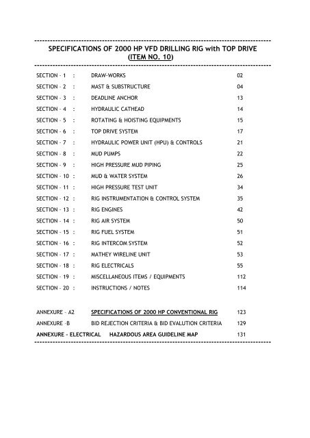
SPECIFICATIONS OF 2000 HP VFD DRILLING RIG with TOP DRIVE<br />
(ITEM NO. 10)<br />
-------------------------------------------------------------------------------------------<br />
SECTION – 1 : DRAW-WORKS 02<br />
SECTION – 2 : MAST & SUBSTRUCTURE 04<br />
SECTION – 3 : DEADLINE ANCHOR 13<br />
SECTION – 4 : HYDRAULIC CATHEAD 14<br />
SECTION – 5 : ROTATING & HOISTING EQUIPMENTS 15<br />
SECTION – 6 : TOP DRIVE SYSTEM 17<br />
SECTION – 7 : HYDRAULIC POWER UNIT (HPU) & CONTROLS 21<br />
SECTION – 8 : MUD PUMPS 22<br />
SECTION – 9 : HIGH PRESSURE MUD PIPING 25<br />
SECTION – 10 : MUD & WATER SYSTEM 26<br />
SECTION – 11 : HIGH PRESSURE TEST UNIT 34<br />
SECTION – 12 : RIG INSTRUMENTATION & CONTROL SYSTEM 35<br />
SECTION – 13 : RIG ENGINES 42<br />
SECTION – 14 : RIG AIR SYSTEM 50<br />
SECTION – 15 : RIG FUEL SYSTEM 51<br />
SECTION – 16 : RIG INTERCOM SYSTEM 52<br />
SECTION – 17 : MATHEY WIRELINE UNIT 53<br />
SECTION – 18 : RIG ELECTRICALS 55<br />
SECTION – 19 : MISCELLANEOUS ITEMS / EQUIPMENTS 112<br />
SECTION – 20 : INSTRUCTIONS / NOTES 114<br />
ANNEXURE – A2 SPECIFICATIONS OF 2000 HP CONVENTIONAL RIG 123<br />
ANNEXURE –B BID REJECTION CRITERIA & BID EVALUTION CRITERIA 129<br />
ANNEXURE – ELECTRICAL HAZARDOUS AREA GUIDELINE MAP 131<br />
-------------------------------------------------------------------------------------------
Page 2 of 133<br />
SECTION 1: DRAW-WORKS<br />
DRAW-WORKS<br />
One (1) 2000 HP AC variable frequency drive (VFD) draw-works with under-noted features<br />
/specification:<br />
The Single or Dual Speed Gear Driven approximately 500 Short Ton (454 MT) capacity, 2000 HP<br />
(1491 kW) rated draw-works with Single / Dual speed gear box mounted directly onto the drum<br />
shaft. The drum shaft to be mounted on spherical roller bearings bolted to the draw-works frame.<br />
The drum directly driven by the dual speed gear box. The motor shaft to be connected to the gear<br />
box input shaft using a gear tooth coupling to reduce the overall size & weight and to reduce down<br />
time for motor replacement. Shifting between high/low speeds under no load/no speed conditions<br />
using air powered shifting mechanism for Dual speed gear boxes. This feature to be integrated into<br />
the driller‟s Amphion or similar controls for the draw-works.<br />
Primary/dynamic braking to be performed with AC motors by generating power into braking<br />
resistors. The motor and frequency drive should be capable of holding full load at zero speed. Load<br />
and speed is limited within motor capacity by the control system.<br />
A pneumatically operated multi-plate disc brake system should be provided for parking and<br />
emergency situations, consisting of multi-plate air / water cooled discs with spring applied brake,<br />
static braking by springs expanding & forcing all the brake discs together (fail safe). The brake<br />
assembly is to be mounted to the end of the drum shaft & is secured to the drum support uprights.<br />
This multi-plate disc brake system should be operated remotely via the draw-works Amphion or<br />
similar control system. Emergency brake controls on the draw-works should allow the load to be<br />
manually lowered using the multi-plate disc brake system.<br />
Specifications:<br />
Input Rating<br />
: 2,000 hp (1491 kW)<br />
Number of Motors : 2<br />
Hoisting Capacity<br />
: 480 Short Ton (435 MT or 960,000 lbs) with 12 Lines<br />
Nominal depth rating : 6096 M (20,000 ft) with 4.1/2” OD drill pipe of length range 30-31 ft.<br />
Drum Grooving<br />
: Lebus Type either for 1.3/8” or 1.1/2” wire line.<br />
Auxiliary Brake<br />
: 1 (Multi disc type brake system)<br />
Disc Brake Cooling : Air / water<br />
AC CAGE INDUCTION MOTOR, MIN. 1100 HP, VFD<br />
Two (2) 1100 HP (minimum) each AC cage VFD induction motors in accordance with the following:<br />
AC induction motors, designed specifically to handle jobs with typically heavy loads for continuous<br />
draw-works oilfield drilling duty. High quality materials, heavy duty construction, state of the art<br />
design technology and ISO 9001 manufacturing standards ensuring reliable performance in the<br />
naturally hostile oil rig environment.<br />
Features:<br />
At continuous horsepower : 880 to 1400 RPM, Max Speed 3000RPM<br />
Minimum 1100 HP continuous, 3pH, 600V, 1440 amps continuous<br />
VF drive constant torque 0-880 RPM (9050 Ft. - lbs), 45ÚC Ambient<br />
Class H VPI form wound<br />
IP44 Enclosure<br />
Approximately 7000 lbs<br />
Two heavy duty anti-friction bearings, re-greaseable, insulated<br />
Single shaft with hub<br />
RTDs: 6 x PT100, 2 per phase in stator 2 x PT100, 1 bearing
Main terminal box IP56<br />
Differential Pressure Switch<br />
Space Heater<br />
Mounting dimensions same as GEB 28<br />
Blower Assembly 20 HP, 480/3/60 4200 CFM Minimum<br />
Mounted Encoder, Avtron or similar<br />
Page 3 of 133
Page 4 of 133<br />
SECTION 2: MAST & SUBSTRUCTURE<br />
MAST<br />
One (1) “Swing lift” Cantilever Beam Leg Mast. Floor mounted cantilever open face mast, designed<br />
in accordance with latest API spec. 4F (PSL 1, SSL E2/U2). "Drilling and Well Servicing Structures".<br />
Mast should be designed to accommodate a 500 Short Ton (454 MT or 1,000,000 lbs.) capacity<br />
portable top drive system.<br />
MAST & ACCESSORIES<br />
1. Minimum 142 ft. (43.28 M) clear height x 30 ft. (9.14 M) base mast stem, single front leg, single<br />
pin connected, with raising sheaves and shafts, cat line sheave brackets, and tugger sheave<br />
bracket.<br />
2. One (1) A-frame assembly consisting of one pair of front and rear A-frame legs with raising<br />
sheaves, mast drive pins, bolts & deadline anchor support mounted either on the mast leg or substructure<br />
basement or at any appropriate position on driller‟s side. Hydraulic snubbing system to<br />
be installed in „A‟ frames allowing driller to have full control of “break-over” during the raising and<br />
lowering operation. The snubbing system should be complete with FLP electric motor driven<br />
hydraulic pumping unit & controls.<br />
3. Full height straight ladder (complete with carrier rail, clamps, safety cage & two safety belts)<br />
with at least three rest platforms between drill floor & crown. The ladder lengths should be<br />
equal to Mast Sections for ease of transportation<br />
4. Mast sections should be equipped with lifting eyes. Tested & certified.<br />
5. Mast section should be so designed in order to meet the transportation dimensions as indicated<br />
in Section - 20 using heavy duty oilfield truck tractor / trailer.<br />
6. Mast should be designed to operate in humid weather environment with relative humidity<br />
ranging from 50 – 100% & temperature range of 6° C to 41° C.<br />
MAST SPECIFICATIONS<br />
Mast clear height : Not less than 142 ft. (43.28 M)<br />
Base width : Not less than 30 ft. (9.14 M)<br />
Static Hook load Capacity : With 12 lines strung on traveling block, min. 500 Short Ton<br />
(454 MT or 1,000,000 lbs.)<br />
Maximum wind load Capacity : 115 mph (185 Kmph) - no setback<br />
Maximum wind load Capacity : 100 mph (160 Kmph) - with rated setback<br />
WINDLOADING SPECIFIED TO MEET API 4F SPECIFICATIONS AND DESIGN CRITERIA.<br />
(Note: The raising of the mast should be possible with 10 lines.)<br />
7. One (1) set of suitable capacity Leveling Equipment for Mast with shims, i.e. hydraulic jacks, hand<br />
pumps, hoses, gauges and connections. Bidder to indicate the capacity, make & model of offered<br />
jacks.<br />
8. Two (2) single mast boom kit 2.5 Short Ton (2.27 MT or 5,000 lbs) capacity, around 6.1 M (20<br />
ft.) long boom & complete with 203.2 mm (8 inch) snatch blocks, brackets and support line for<br />
mounting on both the rear mast leg.<br />
9. One (1) set of mast raising lines with equalizer unit. (Draw-works & drill floor to be raised to<br />
drilling position by use of power from the draw-works & mast raising lines. Mast raising lines<br />
need only to be moved from „A‟ frame sheaves to sheaves on drill floor elevators to complete<br />
rigging for erection.
Page 5 of 133<br />
10. One (1) 305 mm (12 inch) survey sheave unit, grooved .092" with tapered bearing mounted<br />
beneath crown frame at suitable place.<br />
11. Two (2) 355.6 mm (14 inch) tugger (cat line) sheave unit, grooved 5/8" wire line and swivel<br />
mounted, with tapered roller bearings, swivel mounted beneath crown frame.<br />
12. Clause deleted<br />
13. One (1) 55 Short Ton (50 MT or 110,000 lbs) hanging pad eyes for hanging the traveling block<br />
& top drive.<br />
(Note: All pad eyes to be tested to one & half the S.W.L & certified according to API. All<br />
pad eyes to be painted safety yellow & marked with the SWL limit.)<br />
14. One (1) block hanging line to hold traveling block when slipping drill line, approx. 108' long x<br />
1-1/4" (33 M x 31.75 mm).<br />
15. Four (4) sets of Dual Stand pipe Clamps for 127 mm (5 inch) diameter standpipe to be<br />
provided on off-Driller‟s side of Mast complete with clamp cups & bolts.<br />
16. One (1) set of mast stands equipped with lifting pad eyes (one around 1.8 M (6 ft) high for<br />
supporting the mast during assembly & another around 4.9 M (16 ft) high for supporting the<br />
mast during assembly of racking board) & complete with wooden headrest.<br />
17. Access platforms (fold up) with safety belt rope connecting loop to be provided at:<br />
a) Stand pipe gooseneck connection.<br />
b) Casing stabbing board.<br />
b) Sheave unit lubrication position.<br />
b) The platforms less handrails.<br />
18. Pad eyes mounted in mast to accommodate:<br />
Two (2) – 10 Short Ton (9 MT or 20,000 Lbs) cat line sheaves<br />
One (1) – 10 Short Ton (9 MT or 20,000 Lbs) core line unit<br />
One (1) – 55 Short Ton (50 MT or 110,000 Lbs) hang-off line for traveling block<br />
RACKING PLATFORM<br />
Heavy duty Racking Platform with a Capacity for racking at least 220 stands (in thribbles) of 5”<br />
O.D. drill pipe of Range–II and 8 stands (in thribbles) of 8” drill collar and 4 stands of 9 ½” / 10”<br />
drill collar. The length of each single will be in the range 9.14 M to 9.44 M (30 ft to 31 ft) & hence<br />
the thribbles length will be 27.43 M to 28.35 M (90 ft to 93 ft).<br />
<br />
<br />
<br />
<br />
<br />
<br />
<br />
It should be side racking type with adjustable & foldable centre diving board with hinged<br />
extension.<br />
Adjustable from 25 M to 26.5 M (82 ft to 87 ft) above drill floor level complete & complete<br />
with safety chains on all fingers and expanded metal 2‟ wide walkways on three sides.<br />
Fold up floor slab on the fingers on the driller‟s side (initially the pipes will be racked in fingers<br />
on off-driller‟s side till it is full, during this time the fingers on driller‟s side will remain covered<br />
with foldable floor slab for safety reasons).<br />
Racking board access platform with at least 1 M (3‟-6”) high Handrails & toe plate on three<br />
sides.<br />
Geronimo escape line system with easy and safe access.<br />
One (1) Sure-Lock retractable lifeline complete with ground brackets & to be mounted<br />
above diving board.<br />
Mounting bracket to accommodate pullback winch.
Page 6 of 133<br />
TUBING (BELLY BOARD)<br />
One (1) tubing support frame (no fingers) mounted at around 45‟ elevation above drill floor,<br />
complete with walkway, and 1 M (3‟-6”) high handrails with toe plates and access to mast ladder.<br />
TONG COUNTERWEIGHTS<br />
Two (2) sets of tong counterweight buckets mounted on mast leg & complete with guides, snatch<br />
blocks, wire lines, etc.<br />
One (1) spin-up wrench counterweight bucket, guide and sheave unit, located at convenient place<br />
towards the off-driller‟s side.<br />
CROWN BLOCK ASSEMBLY<br />
One (1) 650 Short Ton (590 MT or 1,300,000 lbs.) capacity Crown Block Assembly conforming to API<br />
Specification 4F & consisting of:<br />
- Working cluster consisting of at least six (6) nos. of minimum 60” (1524 mm) diameter sheaves,<br />
grooved for 1-3/8” or 1-1/2” diameter wire line complete with tapered roller bearings. Shaft<br />
drilled with greased fitting for each bearing with grease seals.<br />
- One (1) no. of minimum 60” (1524 mm) diameter fast line sheave, grooved for 1-3/8” or 1-1/2”,<br />
complete with bearing shaft and grease seals.<br />
- The cluster & fast line assemblies to be mounted on a high strength minimum weight crown frame<br />
fabricated from steel shapes and plate.<br />
- One (1) set of wooden bumper blocks for safety.<br />
- Shaft mounting pedestals for working cluster and fast line sheave.<br />
- Line guards complete with sheave guard.<br />
- Crown safety platform with checker plate flooring with at least 1 M (3‟-6”) high handrails and toe<br />
plates, safety gate at ladder opening, and frame lifting eyes.<br />
- A suitably rated rotating jib crane mounted on crown platform, complete with snatch block,<br />
pulleys, etc. to be used for sheave repair / replacement.<br />
- One (1) 20” (508 mm) diameter core line sheave unit, grooved for 9/16” dia. Wire line mounted<br />
on tapered bearings (with hanging pad eyes).<br />
- Two (2) 16” (406 mm) diameter cat line sheave units, grooved for 5/8” dia. Wire line mounted on<br />
tapered bearings (with hanging pad eyes).<br />
- Two (2) 14” (356 mm) diameter Air Hoist sheave units, grooved for 9/16” dia. Wire line mounted<br />
on tapered bearings (with hanging pad eyes).<br />
CASING STABBING BOARD<br />
One (1) air powered heavy duty counterbalanced Casing Stabbing Board with the following features:<br />
• Frame should be heavy duty, fabricated from beams.<br />
• Unit to permit travel from 7 M to 14 M (23 ft to 47 ft) above drill floor.<br />
• Platform should be raised and lowered by air operated chain hoist / wire-line. The chain / wireline<br />
attaches to the platform at a spring -loaded safety latch, ensuring that the safety latch<br />
engages at any loss of tension in the chain.<br />
• The hoist should be equipped with a positive engaging brake.<br />
• The platform should include a foot operated latch for fixing the platform at the desired<br />
elevation.<br />
• The platform and handrails should fold against the tracks when the unit is out of service..
Page 7 of 133<br />
SUBSTRUCTURE<br />
One (1) Light Weight Substructure designed to split for transport. Substructure section should be so<br />
designed in order to meet the transportation dimensions as indicated in Section - 20 using heavy<br />
duty oilfield truck tractor / trailer.<br />
SPECIFICATIONS<br />
Height and Base:<br />
Floor – Minimum 25‟ (7.62 M) overall height with at least 21‟ (6.40 M) clear height under rotary<br />
beams.<br />
Minimum Floor Dimensions:<br />
Length – 35‟ (10.67 M) x Width – 40‟ (12.19 M)<br />
(Excluding the Doghouse and ODS wing supports.)<br />
Capacities:<br />
Setback – Minimum 300 Short Ton (272 MT or 600,000 lbs).<br />
Rotary – Minimum 500 Short Ton (454 MT or 1,000,000 lbs).<br />
Designed to accommodates – 2000 HP VFD Draw-works<br />
(Note: The setback load is simultaneous with the hook load & /or the rotary load)<br />
RIG-UP<br />
The swing lift self elevating substructure with aforesaid drill floor should be supported by welded<br />
box sub-bases around 18 M (59 ft) long x 2.4 M (8 ft) wide x 1.37 M (4 ft – 6 inches) high on both<br />
sides, including cross tie members to hold sub-bases apart during assembly & erection of the<br />
structure.<br />
The sub-bases (bottom boxes) to be complete with Mast & „A‟ Frame shoes, 0.6 M x 0.6 M (2 ft x 2<br />
ft) access window on the Driller‟s side for Air, water & BOP closing lines entry and two 8 Cubic<br />
meter (50 Barrels US) capacity water tanks one in each sub-base near to the rear of the rig<br />
constructed of plate ends and top with man-ways & covers, a 50.8 mm (2 inch) diameter vent pipe<br />
and a 101.6 mm (4 inch) drain plug to be fitted.<br />
Draw-works & drilling floor to be raised to drilling position by use of draw-works power & mast<br />
raising lines, no other rigging or wire line required. The process of rigging up the mast & floors<br />
using the draw-works power should complete in around 30-40 minutes including the time for mast<br />
pinning.<br />
Substructure should be complete with all bracing & support material while in an erect position and<br />
has been constructed in accordance to API 4F specification latest edition.<br />
The „A‟ frames to be assembled to sub-bases and are to be folded into them for transportation, the<br />
transport height should be approx. 2.7 M (9 ft). „A‟ Frames can be erected with a Gin Pole Truck.<br />
No. „A‟ Frame spreader is required. Front end of sub-bases (Bottom Box Extensions) can be<br />
removed for ease of entry of the BOP stack & during the drilling operation.<br />
Special alignment guides to be provided whereas applicable for faster assembling of components.<br />
DRILL FLOOR<br />
One (1) set of drill floor panels with ¼” thick checkered plate for the substructure and 3/8” thick<br />
checkered plate around the rotary area and should be complete with handrails 1 M (3‟-6”) high<br />
with toe plates for the perimeter of the drill floor. Most of the drill floor panels, handrails and<br />
floor mounting equipments to be set into position at ground level and raised with the Draw-works &<br />
setback support.<br />
A minimum of four (4) lifting rings / slots for each section of the drill floor panel to be provided.
Page 8 of 133<br />
ROTARY BEAMS & ROTARY FLOOR SUPPORT UNITS<br />
One (1) set of rotary beams & rotary floor support units designed to accommodate a 952.5 mm<br />
(37.1/2 inch) independent drive rotary table. The rotary floor should be flush with the drill floor /<br />
working floor.<br />
ANTI-SLIP MATTING<br />
One (1) set of anti-slip vinyl / rubber matting (maximum thickness 5 mm) for working area of around 3<br />
feet (914 mm) circumferentially on floor all along the rotary table . The matting should be fixed over<br />
the checkered plate flooring.<br />
ROTARY / SETBACK SPREADER<br />
One (1) rotary/setback spreader complete with framed mouse hole opening, and recess to<br />
accommodate 6” (152mm) thick timber (or canvas reinforced rubber composite) over 3/8" (9.5mm) flat<br />
plate.<br />
Pin tabs are equipped with drop through stops (safety locks).<br />
Reinforced floor with 152.4 mm (6 inches) thick Timber or canvas reinforced rubber composite<br />
installed.<br />
The parallogram type setback support should be designed to support at least 300 Short Ton (272 MT<br />
or 600,000 lbs) of racked pipe simultaneously with 500 Short Ton (454 MT or 1,000,000 lbs) of<br />
casing load. The setback support is to be pinned to the Mast while in the horizontal position &<br />
raised with the mast.<br />
GRASS HOPPER & CABLE ELEVATOR<br />
One (1) Grasshopper type cable elevator with box for collecting cables for rig movement should be<br />
furnished.<br />
STAIRS & HANDRAILS<br />
Three (3) sets with 1 M (3‟-6”) handrails, two from substructure floor to ground and one from<br />
substructure to mud tank (stairs with serrated bar grating).<br />
One (1) lot of 1 M (3‟-6”) high removable handrails (1 ¾” pipe) around perimeter of the working<br />
floor with toe board.<br />
V-DOOR RAMP & STAIRS<br />
One (1) around 7.62 M (25 ft) high ramp 1.8 M (6 ft) wide with 12.7 mm (½”) thick plate down to<br />
the 1066.8 mm (42 inch) high catwalk elevation with framing and stairs continuing to ground level<br />
& complete with 76.2 mm (3 inch) diameter x 0.61 M (2 ft) high pipe rail on both sides of the ramp<br />
adjacent to the stairs.<br />
The stairs to be located on the driller‟s side and should have 1 M (3‟-6”) removable handrails on<br />
one side only.<br />
CATWALK<br />
One (1) around 1066.8 mm (42 inch) high x 1524 mm (5 ft) wide x 14.6 M (48 ft) long catwalk, made<br />
in two sections (length wise). Top with 9.5 mm (3/8 inch) thick smooth MS plate with 19 mm (¾<br />
inch) plate x 1524 mm (5 ft) long on ramp end & catwalk end bumper stopper and complete with<br />
anchor post & lift eyes for each section.<br />
TONG BACK-UP<br />
Set of two (2) tong back up supports bolted to rig floor.
Page 9 of 133<br />
PADESTALS FOR AIR WINCHES<br />
Two (2) mounting pedestals for air winches located on drill floor (one on driller‟s side & other on<br />
off-Driller‟s side).<br />
RATHOLE & MOUSEHOLE<br />
To provide openings for rat hole and mouse hole assemblies. O.D. – 273 mm (10-3/4 inch)<br />
One (1) Rat hole guide for drilling out rat hole at ground level.<br />
RECEPTACLE FOR IRON ROUGHNECK<br />
One (1) suitable receptacle for ST-120 Iron Roughneck of National <strong>Oil</strong>well Varco should be provided<br />
on rig floor at appropriate position for installation of Iron Roughneck in future.<br />
DOGHOUSE AND ODS TOOL ROOM SUPPORTS<br />
Two (2) sets of folding floor modules supports to accommodate doghouse on driller‟s side & tool<br />
room on off-Driller‟s side each on two (2) supports. Support pins to driller's and off-driller‟s side<br />
floor elevator boxes.<br />
DOGHOUSE / DRILLER‟S CABIN<br />
As described in Section – 12.<br />
TOOL ROOM<br />
One (1) tool room not less than 3.66 M (12 ft) long x 2.44 M (8 ft) wide x 2.44 M (8 ft) high mounted<br />
on a three runner skid with load rolls. Exterior side panels fabricated of 4.76 mm (3/16”) crimped<br />
wall panels and top of skid deck covered with 6.35 mm (¼ inch) checkered plate, doghouse should<br />
be complete with:<br />
One (1) personnel door<br />
One (1) window to view well<br />
One (1) window to view exterior<br />
One (1) ladder for roof access<br />
Two (2) tool box/bench 8ft long<br />
One (1) set of interior lights<br />
DRILLING LINE SPOOLER<br />
One (1) electric / hydraulic powered drilling line spooler, Capacity: not less than 1524 M (5,000 ft) of<br />
1.3/8” or 1.1/2" diameter wire rope, designed to spool, unspool and store drilling line.<br />
FEATURES -<br />
1. The customer supplied steel spool of wire rope is installed on the spooler shaft where it is<br />
driven by adjustable pins. The dimensions of steel spool are:<br />
Maximum OD = 1.88 M (74”)<br />
Maximum outer width (flange to flange) = 1.448 M (57”)<br />
Maximum flange thickness = 101 mm (4”)<br />
Central bore diameter = 130 mm (+1 mm, –0 mm)<br />
2. Split pillow block bearing housings allow for easy removal and installation of the spooler<br />
shaft for wire rope spool replacement.<br />
3. The spooler shaft chain drive is engaged by the motor sprocket to provide a positive drive<br />
for the wire rope spool. It can be dis-engaged to allow the spool to free wheel.<br />
4. The spooler shaft and drive assembly is mounted on a heavy duty structural steel frame.<br />
5. Lifting lugs and tie-down bolt holes are provided on the spooler frame for handling and field<br />
installation.
Page 10 of 133<br />
DRILLING / CASING LINE<br />
One (1) reel / spool of 1.3/8” or 1.1/2" drilling / casing line, 6 X 19, Right Regular Lay, IWRC, IPS,<br />
length approximately 1524 M (5000‟), conforming to API Spec. 9A latest edition & with API<br />
monogram embossed. The dimensions of spool should meet the dimensions specified under the<br />
heading “DRILLING LINE SPOOLER, HYDRAULIC DRIVE”.<br />
FALL ARRESTER WITH FULL BODY HARNESS<br />
Two (2) Self retracting lifeline with 20 M (65 ft) of 3/16" galvanized cable and a full arrest body<br />
harness.<br />
BOP TROLLEY BEAMS & BOP HANDLING SYSTEM<br />
One (1) set of BOP trolley beams designed to pin under the substructure floor allowing for front entry<br />
of BOP stack.<br />
One (1) set of complete manually / pneumatically operated BOP handling system complete with<br />
necessary trolleys, hoist, etc. with a system capacity of not less than 20 Short Ton (18.14 MT or<br />
40,000 lbs) having vertical lift of around 4.3 M (14 feet).<br />
ESCAPE SLIDE<br />
One (1) escape slide constructed in steel designed to suit the floor height and to move personnel<br />
from the rig floor in an emergency to be provided on driller‟s side. Escape slide to break down into<br />
transportable sections with limitations as indicated in Section - 20.<br />
AIR WINCH FOR RACKING BOARD<br />
One (1) Ingersoll-Rand make BU7A Classic Air Winch for Racking Board having a capacity of at least<br />
0.5 Short Ton (0.45 MT or 1000 lbs) having the following features:<br />
Enclosed construction which excludes dirt and dust, seals in oil and grease, and assures<br />
complete lubrication of all moving parts.<br />
Ball and roller bearings reduce friction.<br />
Reliable band type brake for holding rated load.<br />
Disengaging clutch (permits free wheeling of the rope drum for hand unwinding).<br />
Powerful radial piston air motor gives positive starting with precise control.<br />
Self-closing throttle shuts off automatically when released, giving well graduated control for<br />
spotting loads.<br />
Reversible motor permits full control of load by the throttle when lifting, lowering and pulling.<br />
Throttle Valve is designed to eliminate air leakage when the winch is idle.<br />
Minimum 3.5:1 design factor at first layer stall load.<br />
Minimum 5:1 design factor at half drum load rating.<br />
Includes Drum Guard<br />
1000 lbs Capacity (Mid Layer Rated)<br />
AIR WINCH (MAN-RIDER)<br />
One (1) Ingersoll-Rand make FA2MRA-24MA1G Air Winch having the following features:<br />
- ANSI/ASME A10.22 rated Man rider winch<br />
Personnel Ratings at 8 to 1 design factors:<br />
- 1.1 Short Ton (1 MT or 2200 lbs) capacity<br />
- 28 mts./min. (92 fpm) line speed up (at 2200 lbs)<br />
- 21 mts./min. (71 fpm) line speed down (at 2200 lbs)<br />
Utility Ratings at 5 to 1 design factors:<br />
- 1.76 Short Ton (1.6 MT or 3520 lbs) capacity<br />
- 20 mts./min. 66 fpm line speed down (at 3520 lbs)
Page 11 of 133<br />
- Battery powered line speed monitor with 120 volt charger<br />
- Dual drum brakes, one automatic and one manual<br />
- Up and down limit switches<br />
- Winch mounted control with automatic spring return “lift & shift” double action throttle lever<br />
to prevents accidental starts<br />
- Drum Guard<br />
- 122 M (400 ft) of 12.7 mm (½ inch) wire rope spooled on drum (IWRC, EIPS, 6 x 36, RRL, nonrotating)<br />
AIR WINCH (DRILLING USE)<br />
Two (2) Ingersoll-Rand make Model FA5A-24XK1G Air Winch having the following features:<br />
- Force-Five „Third Generation‟ air winch<br />
- 5 short Ton (4.54 MT or 10,000 lbs) Line pull (half drum)<br />
- Variable line speed to 50 fpm (half drum)<br />
- 4 short Ton (3.63 MT or 8000 lbs) line pull (full drum)<br />
- Variable line speed to 62 fpm (full drum)<br />
- First layer (max) stall should be 8.5 Short Ton (7.7 MT or 17,000 lbs).<br />
- Average cfm: 700<br />
- 610 mm (24 inch) drum length<br />
- Automatic disc brake<br />
- Winch mounted throttle control<br />
- Drum guard<br />
- Filter (with drain)<br />
- Lubricator<br />
- Strainer<br />
- Muffler<br />
Meets ASME 30.7 Safety Standard & should be complete with One (1) 183 M (600 ft) of 5/8” wire<br />
rope spooled on drum (IWRC, EIPS, 6 x 36, RRL, bright, Non-rotating)<br />
CHECK LIST & DOCUMENTATIONS FOR SECTION 1 & 2<br />
TECHNICAL<br />
Sl.<br />
No.<br />
1 Draw-works<br />
2 Mast<br />
3 Crown Block<br />
4<br />
PARAMETERS/REQUIREMENTS<br />
Racking / Tubing<br />
Board<br />
a<br />
b<br />
c<br />
d<br />
e<br />
f<br />
g<br />
a<br />
b<br />
c<br />
a<br />
b<br />
c<br />
a<br />
b<br />
Input Horsepower<br />
Nominal Depth Rating<br />
Hoisting Capacity<br />
Drilling line size<br />
Lubrication system<br />
Greasing System<br />
Auxilary brake<br />
Clear Height from ground<br />
Static hook load Capacity<br />
Wind load resistance<br />
Capacity<br />
No. of Sheaves<br />
Drilling line diameter<br />
Capacity<br />
Adjustable height range<br />
BIDDER’S OFFER<br />
(To indicate details or<br />
yes/no, as applicable)<br />
REMARKS, IF<br />
ANY
Page 12 of 133<br />
5 Sub-structure<br />
a<br />
b<br />
c<br />
d<br />
Static rotary capacity<br />
Pipe set back capacity<br />
Combined capacity<br />
Work floor dimensions<br />
DOCUMENTATIONS<br />
Sl.<br />
No.<br />
DESCRIPTIONS<br />
1 Technical leaflets with detailed dimensional diagram and<br />
specifications, Make & Model of draw-works, auxilary brake, mast,<br />
sub-structure, etc.<br />
2 Copies of API Certificates & Authorizations (if any)<br />
DOCUMENT<br />
ENCLOSED<br />
Yes or No<br />
REMARKS,<br />
IF ANY<br />
Signature<br />
Name<br />
Designation<br />
Date<br />
_________________________<br />
_________________________<br />
_________________________<br />
_________________________
Page 13 of 133<br />
SECTION 3: DEADLINE ANCHOR<br />
One (1) 50 Short Ton (45.4 MT or 100,000 lbs) minimum capacity, National <strong>Oil</strong>well Varco or Dreco<br />
make deadline anchor suitable for use with 1.3/8” or 1.1/2” casing / drilling line. The deadline anchor<br />
should be designed and manufactured to API Specification 8C latest edition, PSL-1.
Page 14 of 133<br />
SECTION 4: HYDRAULIC CATHEADS<br />
Two (2) Hydraulic Catheads, National <strong>Oil</strong>well Varco make, mounted on a heavy fabricated steel<br />
main frame & tied down to rig flooring for use in conjunction with tongs on the drill floor to either<br />
make-up or break-out tool joints in the drill string & mouse hole.<br />
Type of Catheads : Hydraulic<br />
Operating Line pull (min.) : 11.8 MT (26000 lbs) @ 2000 psi to 14.7 MT (32500 lbs) @ 2500<br />
psi<br />
Stroke : 2.13 M (84 inch)<br />
Cylinder Stroke : 1.07 M (42 inch)<br />
Load indicator : directly in lbs. of line pull<br />
Wire Line : 5/8” or 7/8” Diameter around 12.2 M (40 ft) long (API 9A)<br />
Hydraulic Flow Requirement : 29 to 35 US GPM (110 to 132 lpm)<br />
One (1) Hydraulic power unit, electrically driven with remote control panel (for selecting cathead 1<br />
or 2) & all required lines, accessories, etc. for operating the hydraulic cathead.
Page 15 of 133<br />
ROTARY TABLE<br />
SECTION 5: ROTATING & HOISTING EQUIPMENTS<br />
One (1) 37.1/2” Rectangular base Rotary Table with cover conforming to API Specification 7K latest<br />
edition & with following specification:<br />
Opening: 37.1/2” (952.5 mm)<br />
Static Load Rating: Approximately 650 Short Ton (590 MT or 1,300,000 lbs) 5850 kN<br />
Max. Speed: Not less than 300 RPM<br />
Centre line spacing: 53.1/4” (1352.55 mm) Cathead<br />
INDEPENDENT ROTARY TABLE DRIVE<br />
One (1) suitable independent rotary drive for 37.1/2” rotary table complete with AC Motor, suitable<br />
drive system, Inertia Disc Brake for IRD Component & full guard..<br />
MOTOR FOR INDEPENDENT ROTARY TABLE DRIVE<br />
One (1) Variable speed AC Motor having following specification:<br />
Rated power: Not less than 800 HP (597 kW)<br />
Rated voltage: 600 V<br />
Cooling type: Air forced ventilation 3200 cfm @ 8 inch WC<br />
MASTER BUSHING<br />
One (1) split body pin drive master bushing for 37.1/2” Rotary Table, complete with API No.3 bowl,<br />
Lifting sling, and bit breaker plate.<br />
INSERT BOWLS<br />
One (1) API No. 1 insert bowl for 37.1/2” Rotary Table for use with 11.3/4” – 13.3/8” pipe or casing<br />
complete with lifting sling.<br />
One (1) API No. 2 insert bowl for 37.1/2” Rotary Table for use with 9.5/8” – 10.3/4” pipe or casing<br />
complete with lifting sling.<br />
SPLIT CASING BUSHING<br />
One (1) 37.1/2” x 20” split casing bushing with lifting sling for 37.1/2” Rotary Table.<br />
MUD GUARD<br />
One (1) mud guard complete with lifting eyes & chain for 5” Drill Pipe.<br />
TRAVELING BLOCK<br />
One (1) 500 Short Ton (454 MT or 1,000,000 lbs) capacity traveling block conforming to API<br />
Specification 8C latest edition & with following features & specification:<br />
Features:<br />
Heavy Steel Fabricated Main Frame<br />
Heavy Wireline Guards<br />
Steel Sheaves with Flame Hardened API Wireline Grooves<br />
Tapered Roller Bearings in Sheaves<br />
<strong>Oil</strong> Quenched and Tempered Alloy Steel Pin with Individual Grease Passages to Each Center Pin<br />
Bearing<br />
High Strength Steel Beckett<br />
Specifications:<br />
Load Capacity<br />
: 500 Short Ton (454 MT or 1,000,000 lbs)
Page 16 of 133<br />
Lift eye Capacity<br />
: 65 Short Ton (59 MT or 130,000 lbs)<br />
Number of Sheaves : 6<br />
Minimum Sheave Diameter : 1270 mm (50”)<br />
Wire line size : 1.3/8” or 1.1/2”<br />
Approximate Shaft Diameter : 254 mm (10”)<br />
Coating<br />
: Three Coat Epoxy Paint System<br />
Standard Color<br />
: Safety Yellow
Page 17 of 133<br />
SECTION 6: TOP DRIVE SYSTEM<br />
One (1) 500 Short Ton (454 MT or 1,000,000 lbs) rated AC Top Drive System (Portable) complete<br />
with following:<br />
Motor Housing, Motor Housing Guard, Onboard Hydraulic Power Unit, Roller-style Carriage, Bail,<br />
Pipe Handler, Integral Swivel with Gooseneck & 7500 psi "S-Pipe" assembly and a Shipping/Storage<br />
Skid. Drilling Fluids path pressure limit to be around 7,500 psi (517 bar).<br />
The unit should be equipped with a 7,500 psi Wash Pipe assembly, forced air cooled AC Drilling<br />
Motors (800 HP Total), a 10.5:1 Double Reduction, Helical, quiet Gear Drive, Hydraulic Disc Brakes,<br />
Powered Rotating Head, Bail, and Counterbalance with Stand Jump.<br />
ONBOARD PIPE HANDLER<br />
The on-board Pipe Handler should be complete with 500 ton rated Link Adapter Assembly (Solid<br />
Body Elevator), remote operated, dual crank Upper IBOP Safety Valve, manually operated Lower<br />
IBOP Safety Valve, Lower Gripping Jaw (Torque Back-Up), and Hydraulic Link Tilt assembly. The<br />
Pipe Handler should be dressed for operation with an NC50 API RH tool joint.<br />
ELECTRICAL PACKAGE<br />
Package should include all Electrical Components (cables, cable glands, connectors, junction<br />
boxes, electrical solenoid valves, switches, mounting hardware, etc.) mounted on the Top Drive<br />
Motor Housing Assembly.<br />
Service Loop Termination should preferably be on the RH side of the Top Drive. Solenoid Valves are<br />
operated with 24 Volts DC Power. Drive Motor cooling Blowers powered by 415 Volts, 3 phase, 50<br />
Hz, 4 HP, TEFC motors.<br />
HYDRAULIC PACKAGE<br />
Package should include the Hydraulic Pump with Electric Motor, Misc. Hydraulic components.<br />
Directional Control Valves, Filters, Manifolds and general hydraulic piping components. Electrical<br />
components must comply with DGMS (<strong>India</strong>) requirements for use in Hazardous areas of <strong>Oil</strong> mines.<br />
In other places, wherever mentioned, UL certification shall be considered as equivalent to CMRI<br />
(<strong>India</strong>) certification; however DGMS (<strong>India</strong>) approval shall be binding and final for all equipments to<br />
be used in Hazardous areas as per DGMS Guidelines/ Directive<br />
(Annexure-Hazardous area guideline map may be referred).<br />
CARRIER PACKAGE<br />
Package should include a Carriage (Frame) with rollers for guiding the TDS in the Guide Beam and<br />
for reacting torque from the TDS to the Guide Beam. Also to include the hardware to secure the<br />
Carriage to the TDS and Locking Dogs to secure the TDS in the Shipping Skid.<br />
PIPE HANDLER PACKAGE<br />
Pipe Handler Package should provide for the functions of clamping onto the drill string to provide<br />
Back-Up for making and breaking of the Drill String tool joints at the Top Drive, opening and closing<br />
of Upper IBOP Valve and Hydraulic Elevator Link Tilt. Also to include in the package are one Upper<br />
IBOP valve, one Lower IBOP valve and one Saver Sub for an NC50 API RH tool joint complete with<br />
Locking Rings for the API 6-5/8" Reg connections. The Clamping Mechanism can be positioned to<br />
provide Back-Up for removal and installation of the Saver Subs, Lower IBOP Valve and Upper IBOP<br />
Valve.<br />
This Package configured with IBOP Valves with H2S Trim and for use with 350 Ton Elevator Links.
Page 18 of 133<br />
COUNTERBALANCE PACKAGE<br />
Counterbalance Package should include Counterbalance Cylinders and required hydraulic piping to<br />
integrate with Motor Housing Assembly Hydraulic Piping. For use with Bail lengths up to and<br />
including 120 inches and for applications utilizing a Hook, Block, Block Adapter or with a<br />
Counterbalance Beam.<br />
S-PIPE PACKAGE<br />
Package should include a 7500 psi capable S-Pipe with 20 degree elbow. The connection for the<br />
Rotary Hose should preferably be a Female, 4 inch Fig 1002 or Fig 1003 Union. Pressure rating of<br />
the package, as assembled at the factory, should be 7500 psi. The Rotary Hose connection should<br />
be on the Right Hand side of the TDS (viewing TDS from the front) and positioned toward the front<br />
of the TDS.<br />
The Elbow should have an upper connection to the S-Pipe that is a Fig 1002 or Fig 1003 Union with<br />
the Female half being on the S-Pipe. The Elbow can be removed to have a 4" Female Fig 1002 or Fig<br />
1003 Union pointing straight down for connection of the Rotary Hose directly to the S-Pipe.<br />
BAIL PACKAGE<br />
Package should include an API 500T Swivel Bail with a nominal length of 120 inches, Bail Pins with<br />
retaining devices, Bail Pin Bushings and Counterbalance Cylinder Mounting Brackets. All<br />
components should be factory installed on the TDS.<br />
This package should be suitable for applications using a hook and applications utilizing an Adapter<br />
Becket. The 120" Bail to be used when direct coupling to a Traveling Block.<br />
SHIPPING PACKAGE<br />
Shipping Package should include Lower Section of Guide Beam integrated into a Shipping Skid,<br />
Shipping Support for Pipe Handler and Shipping / Lifting Bar for TDS Bail. Shipping Skid should be<br />
suitable for Tail Boarding and includes lifting shackles.<br />
LUBRICATION KIT<br />
Package should include TDS gear box lubricant, hydraulic system fluid and hand pump for high<br />
temperature service. Suitable for ambient temperatures of around 45°C.<br />
TOOL KIT<br />
Package to include a Lower IBOP Hex Wrench, Valve Seat Wrench and Valve Seat Puller, along with<br />
a NC50 Saver Sub, a Spacer Sub and a Cross-over Sub for use during well-control procedures.<br />
COUNTER BALANCE ATTACHMENT KIT<br />
All required hardware for attaching the Counterbalance Cylinders to the Traveling Block, utilizing<br />
the included Counterbalance Beam.<br />
GUIDE BEAM KIT<br />
The guide beam to provide guided traveling of the Top Drive and torque reaction. Torque to be<br />
transmitted to the derrick/mast structure via the lower tieback. The lower tieback to be designed<br />
to interface with a horizontal spreader beam mounted at approximately 10 ft above the drill floor.<br />
The guide beam should consist of several segments, allowing easy rig-up / rig-down. Configured for<br />
the offered mast height.
Page 19 of 133<br />
BASIC TIEBACK KIT<br />
Kit to include Tieback Link and hardware to tie the lower end of the Guide Beam to a Spreader<br />
Beam or structural member of Mast for lateral and torsional support of the Guide Beam. Also to<br />
include a Guide Beam Intermediate Tieback and a Guide Beam Hang off Link Tieback.<br />
VIDEO MONITORING SYSTEM<br />
Dual Camera video monitoring for top man area to be included at appropriate place for better<br />
control of operations by driller.<br />
KIT, SERVICE LOOP<br />
Kit to include the Power Cables from the point of Mast Termination to the Top Drive, the Auxiliary<br />
Power Cable from the Top Drive thru the Mast Termination & an additional 33.5 M (110 ft) and the<br />
Composite (Multi-conductor Control) Cable from the Top Drive thru the Mast Termination & an<br />
additional 110 feet. All cables to be provided with connectors on each end. Power Cables to be<br />
provided with 4 foot long leads at the Mast end and 3 foot long leads at the Top Drive end. All<br />
cables to be provided with means of securing to the Top Drive and Mast Termination points as well<br />
as Ring Assemblies to secure the cables together between the Top Drive and Derrick Termination<br />
points.<br />
MAST LEG CABLE KIT<br />
To includes three power cables and one ground cable (with suitable connectors on both ends) to<br />
run from the Mast Termination to the TDS Control House. The Kit should be suitable for a cable run<br />
length of 47.2 M (155 ft) from the Mast Termination to the Control House Termination Points. The<br />
Cables to be sheathed together as a single assembly for a length of 41.1 M (135 feet) from the<br />
Derrick Termination suspension point.<br />
MAST TERMINATION KIT<br />
To include mounting brackets for supporting the Power Loop at mid derrick, allowing for quick<br />
disconnect. Also includes Support Saddle for Composite Control Loop, plus mounting hardware.<br />
VDC CABLE ASSEMBLY<br />
Cable assembly should comprise of Twisted and Shield pairs of conductors for communication<br />
between the TDS Drillers Console and the TDS Control House. Including suitable connectors on each<br />
end of the Cable Assembly for connection to the Drillers Console and Control House.<br />
CONNECTION KIT, INCOMING POWER CABLE<br />
Kit should contain Connector Pins, which can be installed at the Power Source. VFD Incoming Power<br />
Cables will interface with these Pins, allowing quick disconnect of VFD / Control House Power at<br />
the source.<br />
CABLE KIT, JUMPER<br />
Should include Power and Composite cables. Cables connect between Control House and the<br />
Derrick Leg Cables.<br />
CABLE KIT, INCOMING POWER<br />
This cable kit is to be used to connect the incoming power from the source (generator set /<br />
transmission line) to the TDS Control House. A connector to be provided on each end of each power<br />
cable assembly.
Page 20 of 133<br />
U-BOLTS & CLAMP for 500 TON ELEVATOR LINK<br />
Set of U-Bolts for accommodating 500 Ton capacity Elevator Links.<br />
Clamp for accommodating 500 Ton capacity Elevator Links.<br />
WELDLESS LINKS (As per API Spec. 8C)<br />
One (1) pair of 350 Short Ton (317 MT) Capacity Weld less Links, 2-3/4" x 120" (70 mm x 3048 mm)<br />
One (1) pair of 350 Short Ton (317 MT) Capacity Weld less Links, 2-3/4" x 132" (70 mm x 3353 mm)<br />
One (1) pair of 500 Short Ton (454 MT) Capacity Weld less Links, 3-1/2" x 120" (89 mm x 3048 mm)<br />
One (1) pair of 500 Short Ton (454 MT) Capacity Weld less Links, 3-1/2" x 132" (89 mm x 3353 mm)<br />
WEAR GUIDE, MASTER BUSHING AND ADAPTER RING, WEAR GUIDE<br />
Wear Guide Assembly to fit into Pin Drive Master Bushing and complete with "U" shaped Base Plate<br />
with split and hinged Wear Guide Ring. Assembly should protect the Master Bushing by limiting the<br />
movement of the Drill Pipe during drilling.<br />
Adapter Ring should fit in the Master Bushing Wear Guide for use with drill pipes. The Adapter Rings<br />
to fit into the same Master Bushing Wear Guide Assembly. This is a component expected to wear in<br />
service.<br />
The master bushing wear guide & adapter ring for wear guide for undernoted drill pipe range:<br />
One (1) set for 3.1/2” to 5” OD drill pipes and<br />
One (1) set for 5.1/2” to 6.5/8” OD drill pipes
Page 21 of 133<br />
SECTION 7: HYDRAULIC POWER UNIT & CONTROLS<br />
All the rig accessories requiring hydraulic power should have independent hydraulic power unit<br />
with standard controls.
Page 22 of 133<br />
SECTION 8: MUD PUMPS<br />
Two (2) 1600 HP (1193 kW) Input Horse Power rated Triplex Mud Pumps, National <strong>Oil</strong>well Model 12-<br />
P-160 with following specifications:<br />
A. TYPE OF PUMP:<br />
Slush pumps triplex single acting, horizontal piston pump with replaceable cylinder liners of various<br />
sizes to obtain desired discharge and pressure at rated SPM, complete with standard equipment,<br />
skidded and master skidded with AC motor.<br />
B. CAPACITY OF PUMP:<br />
Input Horse Power rating : 1600 HP (1193 kW)<br />
Discharge<br />
: Minimum 1575 LPM (416 US GPM) at 351 Kg/sq cm (5000 PSI)<br />
And 2700 LPM (713 US GPM) at 210 Kg/sq cm (2990 PSI)<br />
Discharge pressure : Max. 351 Kg/sq cm (5000 PSI)<br />
The above parameters are to be obtained with replaceable liners and pistons at rated speed of the<br />
pump. Liners to be fitted on the pump at the time of supply to obtain maximum discharge of 3000<br />
Litres/min.<br />
Suitable liners to be fitted with pump to get maximum desired discharge of 3,000 – 3,127 LPM at<br />
working pressure.<br />
C. SLUSH PUMP FEATURES:<br />
a. Fully enclosed steel plate fabrication power end.<br />
b. Double helical / herringbone gear for crankshaft gear and pinion shaft gear.<br />
c. Double extended pinion shaft.<br />
d. Self-aligning spherical main and pinion shaft bearing, Roller bearing at crank and<br />
crosshead end of connecting rod. (Bearing make should be Torrington, SKF or FAG only).<br />
e. Interchangeable standard module (suction and discharge) with shot penned inner surface.<br />
f. Fast change valve covers.<br />
g. Two piece fast change piston rods with clamp.<br />
h. Suction and discharge manifold with suction dampener.<br />
i. Piston - liner lubricant spray system with AC 3 Ph. 50 Hz electric motor driven pump with<br />
reservoir.<br />
j. <strong>Oil</strong>-bath and positive flow lubrication systems<br />
k. External circulating lube oil pump and filter with AC motor, oil gauge and associated<br />
piping<br />
l. The pump should be complete with all the components of fluid end and power end.<br />
D. ACCESSORIES:<br />
Each mud pump package should be assembled with the following accessories:<br />
I. One (1) Discharge Strainer Cross Assembly complete with suitable strainer, 5" (125 mm)<br />
5000 psi (351 Kg/sq cm) WP discharge flange connection, 4"(100 mm) – 5000 PSI (351 Kg/sq<br />
cm) WP top connection for pulsation dampener and 5" (125 mm) - 5000 PSI (351 Kg/sq cm)<br />
WP end connection for strainer clean out.<br />
II.<br />
One (1) 3.1/2” ID (4” API LP thread) x 12‟or15‟ (88.9 mm x 3,657.6 mm or 4,572.0 mm),<br />
vibrator hose Grade D, 5,000 PSI WP, 10,000 PSI TP with fig 1002/1003 integral union (male<br />
& female welded) & hose hobbles(both ends). Built & manufactured according to API spec 7K
Page 23 of 133<br />
III.<br />
IV.<br />
One (1) Discharge Pulsation Dampener (Make- HYDRIL Model- K-20-5000), maximum service<br />
pressure 5000 PSI (351 Kg/sq cm), surge capacity 75 Litres (20 gallons). Connections - 4"<br />
(100 mm) API 5000 RTJ, Diaphragm – Hydrogenated Nitrile or equivalent.<br />
One (1) Pressure gauge (Make- OTECO), 0 - 6000 PSI range with 2" (50 mm) line pipe female<br />
connection, and there should be provision to isolate the gauge with a 2" (50 mm) flex seal<br />
valve (Make- OTECO)<br />
V. One (1) Manual reset (type-B) relief valve, RR, 3"(75 mm) manual reset 1500 – 6000 PSI WP<br />
(Make- OTECO or RETSCO).<br />
VI.<br />
VII.<br />
VIII.<br />
One (1) Charging hose assy. for pulsation dampener<br />
One (1) Jib crane with trolley installed on pump to handle fluid end parts<br />
One (1) Yale hand hoist, 1/2 ton LH 8 Ft lift<br />
E. PUMP DRIVE AND MOTOR SKID:<br />
Dual rear mounted V-belt electric motor pump drive for the offered mud pump, including extended<br />
skid frame, motor supports, tensioning screws, belt guards to be mounted on the master skid.<br />
Pumps are to be fitted with suitable sheaves (including hub) at both sides of pumps. Pump drive<br />
should be complete with banded V-belts for use with AC motor and belt guard.<br />
F. PUMP DRIVE MOTOR:<br />
Each mud pump shall be driven by two (2) heavy-duty AC Induction motor compatible with the mud<br />
pump<br />
All the motors for auxiliary lube oil pump (if any) to be supplied by mud pump supplier should be<br />
rated as follows:<br />
Voltage 3-phase, 415 V, 50 Hz. HP will depend on pump but shall be limited to 5 HP for each<br />
motor. RPM will depend on pump. Terminal box - fitted with double compression type FLP gland<br />
suitable for cable OD 14 mm. Enclosure - flameproof, suitable for use in hazardous area Zone-I gas<br />
group IIA & IIB.<br />
G. MUD PUMP SPARE PARTS & SPECIAL TOOLS:<br />
The following spare parts and tools should be included in the scope of supply. These spare parts &<br />
tools are to be quoted separately indicating part numbers in technical bid and prices in commercial<br />
bid respectively. The cost of these spares & tools will be considered for evaluation of the offers.<br />
However, OIL reserves the right to decide whether to purchase these spare parts along with the<br />
pump or not.<br />
I. Spares for mud pump with required quantity:<br />
a) Liner 7" : 30 No<br />
b) Liner 6" : 36 No<br />
c) Piston Assembly 7" : 48 No<br />
d) Piston Assembly 6" : 60 No.<br />
e) Piston Rod complete : 6 No.<br />
f) Valve seat : 25 No.<br />
g) Valve assy. with polyurethane insert : 100 No<br />
h) Valve Insert (polyurethane) : 200 No<br />
i) Valve spring : 24 Nos.<br />
j) Valve cover gasket : 200 No<br />
k) Liner gasket, 7" : 90 No<br />
l) Liner gasket, 6" : 90 No<br />
m) Wear plate gasket : 12 No
Page 24 of 133<br />
n) Wear plate : 6 No<br />
o) Suction module : 3 No<br />
p) Discharge module : 3 No<br />
q) Banded power belt : 2 No<br />
II. Special Tools:<br />
a) One (1) no. of complete valve seat puller assembly (Type & Make to be specified) suitable for<br />
above mentioned valve seat.<br />
b) One (1) set of special hand tools for fluid end maintenance must be included with each pump<br />
set to be supplied.<br />
c) Suitable Stroke Counter Meter should be provided in each pump.<br />
H. TECHNICAL CHECK LIST FOR MUD PUMP<br />
[THE FOLLOWING CHECK LIST MUST BE COMPLETED AND RETURNED WITH THE OFFER. ALSO ENSURE<br />
THAT ALL THESE POINTS ARE COVERED IN YOUR OFFER. THESE WILL ENSURE THAT YOUR OFFER IS<br />
PROPERLY EVALUATED. PLEASE TICK MARK 'YES' OR 'NO' TO THE FOLLOWING QUESTIONS, IN THE<br />
RIGHT HAND COLUMN]<br />
Sl. No. Points Remarks<br />
1<br />
Whether quoted as OEM of Pump and whether documentary evidences<br />
submitted to this effect?<br />
YES/ NO<br />
2 Whether quoted as Assembler? YES/ NO<br />
3<br />
Whether quoted as Authorized Dealer of OEM (Pump), if so, has the dealer YES/ NO<br />
submitted documentary evidences in this regard?<br />
4 Whether the Pump offered is rated for continuous operation at full load? YES/ NO<br />
5 Whether the offered pump design is of two piece Module? YES/ NO<br />
6<br />
Whether the input HP of the Pump set 1600 HP to obtain the desired<br />
Hydraulics as per our NIT.<br />
YES/ NO<br />
7<br />
Whether the pump offered having double helical (herringbone) main gear & YES/ NO<br />
pinion shaft with double helix gear?<br />
8 Whether the offered pump sets are skidded on a master skid? YES/ NO<br />
9 Whether the pump is equipped with belt driven system as asked for? YES/ NO<br />
10<br />
Whether auxiliary motors are flame proof and suitable for use in hazardous<br />
area?<br />
YES/ NO<br />
11<br />
Whether auxiliary motors are CMRI certified and DGMS approved?<br />
A visual guideline/ map / diagram of demarcation of areas as per DGMS<br />
guidelines is attached as Addendum-Electrical: Hazardous Area<br />
YES/ NO<br />
Guidelines Map<br />
12<br />
Whether detail specifications of Pump along with technical literature /<br />
catalogue /schematic layout (plan & elevation) of the pump offered YES/ NO<br />
enclosed with the offer?<br />
13<br />
Whether spare parts for the offered pump will be available for next 10<br />
years from now?<br />
YES/ NO<br />
14<br />
Whether 3 sets of part list with part numbers, quantity and unit rate<br />
recommended for two years of operation are submitted along with the bid?<br />
YES/ NO<br />
15<br />
Whether separately highlighted any deviation from the technical<br />
specification sought for?<br />
YES/ NO<br />
16 Whether Test Certificates of Pump will be submitted along with the supply? YES/ NO<br />
17<br />
Whether Spares parts & Special tools for the pumps mentioned in Section -<br />
8 para G will be supplied?<br />
YES/ NO<br />
Offer Ref ..................... Dated .....................<br />
OIL's <strong>Tender</strong> No................. Signed ....................<br />
For & on behalf of ............ Designation .................
Page 25 of 133<br />
SECTION 9: HIGH PRESSURE MUD PIPING<br />
HIGH PRESSURE PIPING SYSTEM FOR TWO PUMPS AND DUAL STANDPIPE<br />
One (1) dual 5" (127 mm) x 5,000 PSI (351 Kg/sq cm) WP high mud pressure delivery system for two<br />
mud pumps as follows:<br />
Pressure gauge and relief valve (relief lines to suction tank) at each pump discharge.<br />
Discharge of each pump complete with one 5" (127 mm) x 5,000 PSI (351 Kg/sq cm) WP BW<br />
gate valve and one (1) 5" Fig 1002 or Fig 1003 integral union.<br />
One (1) 3.1/2” ID (4” API LP thread) x 12‟or15‟ (88.9 mm x 3,657.6 or 4,572.0 mm), vibrator<br />
hose Grade D, 5,000 psi WP, 10,000 psi TP with fig 1002/1003 integral union (male & female<br />
welded) & hose hobbles(both ends). Built & manufactured according to API spec 7K<br />
5" XXS substructure lines complete with integral unions at break points and heavy-duty<br />
clamps for mounting. Two vibrator hoses for connecting to standpipe manifold.<br />
Dual standpipe manifold and high pressure piping.<br />
Goose neck with 4" Fig 1002 or Fig 1003 Integral Union<br />
One (1) Kill line kit consisting of a suitable length of XXS pipe (around 150 Mtrs.), swivel<br />
joints & integral unions<br />
One (1) 9.14 M (30 ft) long low pressure fill line hose with 2" Fig 1002 or Fig 1003 Integral<br />
union at each end.<br />
Sufficient no. of additional intermediate 5,000 PSI (351 Kg/sq cm) rated WP pipes to<br />
facilitate extension of the delivery pipe up to 170 ft.; to meet the 15m spacing between the<br />
wells in cluster locations.<br />
NINE VALVE STANDPIPE MANIFOLD<br />
Standpipe Manifold on the Drill Floor should include:<br />
Mud Standpipe Manifold, 5" (127 mm) x 2" (50.8 mm) 5,000 psi (351 Kg/sq cm) WP, Standard<br />
Service.<br />
Mud Gate Valves, 5" (127 mm) Butt Weld XXS, Steel Buna Trim, Standard Service.<br />
Mud Gate Valves, 2" (50.8 mm) Butt Weld XXS, Steel Buna Trim, Standard Service<br />
Gooseneck c/w Integral Bull Plug, 5" (127 mm) 5K Butt Weld XXS, Standard Service.<br />
Forged Block Tee, 5" 5K Butt Weld XXS, Standard Service.<br />
Forged Reducing Block Tee, 5" (127 mm) x 2" (50.8 mm) 10K Butt Weld XXS, Standard Service.<br />
Integral Union,1502 Butt Weld XXS, Standard Service.<br />
Integral Union Sub c/w Nut, 5" Fig 1502 Male Butt Weld XXS, Standard Service.<br />
Integral Union Sub c/w Lip Seal, 2" Fig 1502 Female Butt Weld XXS, Standard Service.<br />
Integral Union Suc/w Nut, 2" Fig 1502 Male Threaded End, Standard Service.<br />
CEMENT STANDPIPES<br />
One (1) single 2" XXS cement standpipe for suitable elevation including gooseneck and 2" Fig 1502<br />
Integral union at gooseneck. Standpipe prepared for welding to rig floor manifold.<br />
VIBRATOR HOSE<br />
3.1/2” ID (4” API LP thread) x 12‟or15‟ (88.9 mm x 3,657.6 or 4,572.0 mm), vibrator hose Grade D,<br />
5,000 psi WP, 10,000 PSI TP with fig 1002/1003 integral union (male & female welded) & hose<br />
hobbles(both ends). Built & manufactured according to API spec 7K.<br />
ROTARY HOSE<br />
Two (2) 3" or 4” (76.2 mm or 101.6 mm) ID, 10,000 PSI (702 Kg/sq cm) test pressure, 5000 PSI (351<br />
Kg/sq cm) Working Pressure rotary hoses with 4" Fig 1002 or Fig 1003 Integral Union (Male x<br />
Female) as per API spec. 7K with Safety Clamp and Chain (on both ends) of appropriate length<br />
(bidder must indicate the length in technical bid).
Page 26 of 133<br />
SECTION 10: MUD & WATER SYSTEM<br />
MUD & WATER TANK SYSTEM WITH ACCESSORIES:<br />
One (1) Mud & Water Tank System consisting of the following:<br />
1A: Active and Reservoir Mud Tanks: 3 + 3 = Six (6) tanks<br />
One (1) Shaker tank – 47.7 cum (300 Barrels US)<br />
One (1) Intermediate tank – 47.7 cum (300 Barrels US)<br />
One (1) Suction tank – 47.7 cum (300 Barrels US)<br />
Three (3) Reserve tanks of Capacity 47.7 cum (300 Barrels US) each (i.e. Total capacity: 900<br />
Barrels US) complete with Mixing Pumps and Mud agitators<br />
1B: Water / Chemical Tanks: Three (3) tanks<br />
1C: Auxiliary Equipment & Accessories for the Mud Tank System:<br />
One (1) Mud Loading System<br />
One (1) Mud Pump Super Charger System<br />
One (1) Feed Pump System for Solid Control System<br />
TECHNICAL DETAILS OF THE ABOVE:<br />
1A: Active and Reservoir Mud Tanks:<br />
Each mud tank should have approximately the following dimensions:<br />
Length: 9900 mm (excluding 300 mm skid extension on each end for tail boarding)<br />
Breadth: 2285 mm<br />
Height: 2250 mm (excluding skid height)<br />
Tank Walls: The walls of each of the tanks (including partition walls) are to be constructed with 8<br />
mm thick MS crimped plates. Tank bottoms, to be constructed with 8 mm thick plain plates,<br />
should be sloped gradually to a maximum of 3” (75.0 mm) towards the tank cleaning doors to<br />
facilitate cleaning.<br />
Master Skid: The tanks should be mounted on three runner oilfield type skids fabricated from 300<br />
mm beams (ISMB) reinforced with suitable channels and angles. The ends of the skid should<br />
project out from the tank by 300mm and curve upwards. 150 NB X Sch 80 pipe with provision<br />
for lifting should reinforce the end of the skids for tail boarding.<br />
Tank Doors: Two (2) clean out gates should be provided at the rear of each reserve, suction and<br />
intermediate tanks and three (3) clean out gates in the shaker tanks.<br />
Sand Traps of approx. 10 – 12 cum capacity are to be provided in the Shaker Tanks. Approx. 3” (75<br />
mm) slope is to be maintained towards the clean out gate end.<br />
Valves and Couplings: Dresser type pipe couplings, butterfly valves and dumb valves with flanged<br />
ends should be provided.<br />
Mud Channels and gates: Mud channel with diversion gates should be provided in all the tanks per<br />
the mud system requirement.<br />
Water, Mud and Equalizing Lines: Square tubings of sizes 152 X 6 mm and 101 X 6 mm shall be<br />
used for Mud rolling line and Water rim line respectively. Equalizing lines (273mm) should be<br />
provided between shaker tank and intermediate tank with dresser type pipe couplings for end<br />
connections. These lines should be provided with suitably placed manifolds / isolating butterfly<br />
valves and gates etc. for separation or isolation of tanks or tank in the system. The rim line<br />
water tapping for mud system shall be with 1” NPT vertical insert and a plug (2 nos. for each<br />
tank). Suction lines of 250 mm (10”) nominal dia with butterfly valves and Dresser type pipe
Page 27 of 133<br />
couplings for two nos. of mud pumps should be provided in the Suction Tank and in the<br />
Intermediate Tank. The suction valves and suction valve system shall be supplied with 10” NB X<br />
6.3 mm thick pipes. Mud hopper suction line of 200mm (8”) nominal dia. with butterfly valve<br />
and Dresser type pipe coupling should be provided in the Suction Tank and all the reserve<br />
tanks.<br />
Tank Top, Handrails and Staircases: All tank top open spaces should be covered with iron serrated<br />
bar gratings (Heavy-duty grills) and should have sufficient support and fixing arrangements to<br />
ensure stiffness and ruggedness. Removable handrails at least 1 metre high with two-rail<br />
railings and 0.15 metre high toe board should be provided on the open side of the tanks per<br />
safety standards. All handrails should consist of top rail, knee rail and tick board. Stairways of<br />
1000-mm width and 45 degree maximum angle with handrails as described above on both sides<br />
should be provided at convenient places for climbing on to the tanks from ground level and<br />
from cable tray to suction tank. These staircases shall be resting on the walkway and also<br />
wherever possible be permanently attached / anchored to the tanks. All tanks should have<br />
fixed staircases without handrails from tank top to tank bottom for going into the tank. The<br />
walkway arrangement shall be Folding type flush with tank top.<br />
Tank Volume Measuring Scale: All the tanks should be provided with permanently attached<br />
measuring scale made of anti-corrosive metal / alloy graduated in inch and foot to indicate<br />
volume per inch height.<br />
Bottom Mud Gun: On the low pressure mud rolling lines a sufficient number of bottom mud guns<br />
complete with nipples, pipes, butterfly valves, hammer unions and a handle to rotate the gun<br />
from tank surface etc. should be provided in all the tanks.<br />
Mud Agitator: Each mud tank shall be equipped with mud agitators so positioned to have proper<br />
churning of mud, each complete with flameproof electric motor(s) of suitable hp (to be<br />
specified by the bidder) which shall operate on 415 Volts, 3-phase, 50 Hz AC power supply. The<br />
mud agitators should be of aerofoil design impeller and heli-bevel type gearbox. The turn-over<br />
rate of the agitators should be around 50 seconds.<br />
Provision for Mounting Solids Control Equipment: Provision should be kept for mounting /<br />
installing solids control equipment on the shale shaker and intermediate tanks. Two (2) shale<br />
shaker units, placed side by side, with shale slide, mounted on Shale Shaker Tank; one (1)<br />
desander unit mounted on shaker tank and one (1) mud cleaner with desilter unit mounted on<br />
suction / intermediate tank; one (1) centrifuge & one (1) vacuum degasser unit mounted at<br />
suitable place on intermediate & shaker tank respectively. The required partitions, outlets with<br />
200 mm(8”) butterfly valves and dresser type couplings should be provided in the shale shaker<br />
tank and intermediate tank for operating all these solid control equipment and degasser in the<br />
mud system. The skid with feed pumps to all these equipment should be placed in front of the<br />
shale shaker/ intermediate tank near their interconnections. A common manifold for suction<br />
and delivery of the feed pumps for solid control equipment is to be provided with isolating<br />
valves to use either of the two pumps to feed desander, desilter or degasser.<br />
Surface Preparation/ Sand Blasting/ Painting: All oil deposits should be removed by using<br />
approved de-greasing agents with special attention to drilled holes, bolt holes etc. The tanks<br />
shall be sand-blasted and painted with one coat of inorganic zinc primer 70 microns in thickness<br />
and two coats of Repack high build polyurethane.<br />
Electrical Earthing System:<br />
(i) Each mud tank should have two nos. of GI straps 50 X 6 mm mounted on the out side<br />
of the walls facing mud pumps and mud mix skid side.<br />
ii) The straps 50 X 6 mm should be welded to the sturdy supports that are welded to the<br />
tank wall. The gap between tank wall and strap: 50mm. Spacing between supports:<br />
1000mm. The strap length should be the same as the tank length/ width. Gap between<br />
straps should be 150mm.
Page 28 of 133<br />
iii) Holes to be drilled in each strap are: (a) one no of 15mm dia. hole near each agitator<br />
(b) two nos. of 15mm dia. holes with a spacing of 100mm near each strap end.<br />
iv) Straps should be mounted at a convenient height for ease of connection.<br />
v) Galvanization of the straps should be of the high quality to withstand the corrosive<br />
environment. 2 nos. each 25 X 3 mm GI strips shall be welded to the main strips and<br />
the agitator skids (approx. perpendicular to the main strips 50 X 6mm).<br />
vi) Two (2) GI straps of size 50 X 6 mm shall be suitably mounted on each skid to facilitate<br />
independent double earthing of the pump motors.<br />
vii) Holes to be drilled in each strap are: a) two nos. of 15 mm dia holes with a spacing of<br />
100 mm near each motor b) two nos. of 15 mm dia holes with a spacing of 100 mm<br />
near each strap end.<br />
viii) Foldable type hangers should be mounted on tank wall below the earthing straps to<br />
support the mud system cables. Spacing between hangers should be 1000mm. Width of<br />
the hangers: 300mm<br />
Mounting of Push button station: Mounting assembly for push button station of each mud/ water<br />
tank agitator to be welded to the tank near respective agitator assembly.<br />
Mud Pill Chamber: A chamber of approx. 12 cum (75 Barrels US) capacity with isolating valves<br />
should be provided inside the suction tank for preparation of special mud pills. A suitable sized<br />
agitator of stainless steel 304 Aerofoil 3 blade design of approx. dia 36” coupled with<br />
flameproof electric drive motor of maximum 10-hp capacity should be provided in this chamber<br />
for proper mixing of the mud additives. The pill tank agitator is to be such that it should not<br />
foul with the bottom/ internal piping. This chamber should be connected with the suction line<br />
for the rig pumps and also with an independent line from the mud loading system with isolating<br />
valves.<br />
Chemical Operator‟s Cabin: One (1) cabin of size approximately 4.2 m long x 2 m wide x 2.5 m<br />
high skid-mounted cabin with proper heat insulation & ventilation, complete with one sliding<br />
door, safety glass windows, adequate provision for keeping mud testing equipment and<br />
accommodating 2 (two) persons, and with tool box, oilfield mud balance such as Baroid and MF<br />
viscometer. The cabin should be placed near the intermediate tank at the level of the<br />
walkways.<br />
Tank should be covered with steel collapsible type stackable system and adequate individual<br />
lighting arrangement and ventilation facility.<br />
1B: Water / Chemical Tanks:<br />
Three (3) water / chemical tanks fabricated as detailed above for item 1(A) and having approx.<br />
dimensions:<br />
Length : 9900 mm (excluding 300 mm skid extension on each end for tail boarding)<br />
Breadth : 2285 mm<br />
Height : 2250 mm (excluding skid height)<br />
Capacity : 47.7 cum (300 Barrels US)<br />
Master Skid for Water / Chemical Tank: One Master Skid having 4 runners with a dimension of 3.05<br />
M (10 ft) wide x 9.75 M (32 ft) long for placing the three water tanks. The skid should be fitted with<br />
two nos. of centrifugal pumps (as Water Booster) having a minimum flow rate of 80 cum per hour<br />
and with 55 mtr. head driven by 40 HP explosion proof 415 volts, 50 Hz, 3 phase electric motors<br />
and complete with suction and discharge lines for operation of either or both pumps<br />
The following features should be provided in the water / chemical tanks: -<br />
Two tanks should have open top and one tank should have covered top with two manholes.
Page 29 of 133<br />
Both the open top tanks should be covered with the serrated floorings as described above at<br />
1A(h).<br />
2” line size hopper shall be fabricated and assembled on one open tank. The maximum height<br />
of the hopper shall be limited to the height of the mud agitator and should not exceed 3400<br />
mm.<br />
Small, rugged, collapsible type platforms of preferable size 2000 mm (L) x 2000 mm (B) x 500<br />
mm (H) should be provided near the hopper to stack a few sacks of chemicals prior to loading.<br />
All the three tanks should be provided with strongly built sturdy ladder both from inside and<br />
outside the tanks. Handrails are to be provided for the two (2) open-top tanks with bar grating<br />
platforms and walkway between the two tanks.<br />
Two (2) clean out gates should be provided at the rear side of each tank. These gates should be<br />
provided with 12” Butterfly valves. Approx. 3” (75 mm) slope is to be maintained towards the<br />
clean out gate side.<br />
All the tanks should be provided with 100 mm drain out plug at the floor of the tanks.<br />
The open tanks should be provided with permanently attached measuring scale made out of<br />
anti-corrosive metal / alloy graduated in inch and foot to indicate volume per inch height.<br />
The inlet feed line shall be supplied with 100 mm (4”) Sch.40 ASTM 106 Grade „B‟ pipes with<br />
butterfly valve and should be anchored firmly with the sidewall of the tank. The rim line water<br />
tapping for water tanks shall be with 1” NPT vertical insert and a plug (2 nos. for each tank).<br />
All the tanks shall be provided with 152.4mm (6”) Sch.40 ASTM 106 Grade „B‟ pipes with<br />
butterfly valve in the front side of the tanks.<br />
The open top tanks should be provided with bottom guns at four sides of the tanks with rotating<br />
(180 0 ) facility from the tank top.<br />
Each open-top tank should be provided with two (2) agitators having heli-bevel type gear<br />
box.The mud agitators shall be with stainless steel 304 Aerofoil 3 blade design of approx. dia<br />
36”. The agitators should be driven by maximum 10 hp, 415 volts, 3-phase, 50 Hz horizontal<br />
foot mounted, squirrel cage rotor induction motor with bi-directional cooling fan at NDE. The<br />
motor should be fully enclosed fan cooled and offering protection to IP55. Insulation: Class F<br />
but the temperature rise should be limited to that of Class B. Earthing: Two nos. of earth points<br />
on the enclosure and one no. inside the terminal box. Termination: Motors should have terminal<br />
box with studs for connection of supply cable. Canopy: Motors should be provided with a<br />
removable type canopy for protection against rain. Canopies should be supported on agitator<br />
skids. Paint: Motors should be painted with epoxy paint of DA Grey shade.<br />
One of the chemical mixing tanks should have two chambers. One of the chambers should have<br />
100-150 bbl capacity. Both the chambers should have independent suction line and one agitator<br />
each. Both the chambers should be connected to hopper for chemical mixing independently<br />
with suitable valve arrangements.<br />
The overall height of the tanks including the agitators should not exceed 3400 mm for<br />
transport limitations.<br />
Two (2) 100 HP electric motor driven horizontal multistage centrifugal pumps set complete with<br />
piping/ Dresser type couplings and butterfly valves should be mounted on an independent three<br />
runner oilfield skid. These pump sets will be used to load chemicals through hoppers to water<br />
tanks, to gun the mixture and to feed chemical-mixed (gauging) water in the cement hopper for<br />
preparation of cement slurry. The two horizontal multi stage centrifugal pumps should have cast<br />
steel body, bronze / cast iron impeller, EN 8 shaft with gland type packing and each should be<br />
capable of developing 150 m. of head. The discharge of each pump should be about 60.0 m 3 / hr at<br />
1450 rpm.<br />
1(C): Auxiliary Equipment & Accessories for the Mud Tank System:<br />
I. Mud Loading System: One (1)<br />
II. Mud Pump Super Charger System: One (1)
Page 30 of 133<br />
III. Feed Pump System for Solid Control System: One (1)<br />
I. Mud Loading System:<br />
The following equipment should be mounted on an oilfield three runner skid and top floor with<br />
inter connections through piping, dresser type couplings and butterfly valves:<br />
Centrifugal Pump sets: Four (4) centrifugal pumps of Mission Magnum – I or equivalent make of size<br />
8” x 6” x 14” with approx. 12.1/2” size impeller. The mud mix system shall be provided with 10”<br />
suction valve system with 8” suction header.<br />
Each pump will be coupled to a 100 hp, 415 Volts, 3-phase, 50 Hz 1500-rpm flameproof<br />
weatherproof electric motor. The motors, starters and the cable glands should be suitable for use<br />
in hazardous areas and duly certified by CMRI (UL or the equivalent certifying authority of the<br />
country of origin)and approved by DGMS for Zone I and Gas group IIA & IIB of <strong>Oil</strong> Mines.<br />
The bidder should submit copies of CMRI certificates (UL or the equivalent certifying authority of<br />
the country of origin) & DGMS approvals for all the flameproof electric motors, starters and cable<br />
glands with the quotation.<br />
In other places, wherever mentioned, UL certification shall be considered as equivalent to CMRI<br />
(<strong>India</strong>) certification; however DGMS (<strong>India</strong>) approval shall be binding and final for all equipments<br />
to be used in Hazardous areas as per DGMS Guidelines/ Directive<br />
(Annexure-Electrical: Hazardous area guideline map may be referred).<br />
Loading Hoppers: Four (4) hoppers shall be provided for Bentonite / Barite loading. Two (2)<br />
hoppers should be suitable for use for loading barites and two (2) other hoppers coupled with two<br />
(2) High Performance Aqua–Shear Jet Shearing / Mixing System capable of handling 1000 GPM of<br />
fluid, should be suitable for loading polymer chemicals. The Jet shearing system shall be provided<br />
with hopper having 4” line size on a separate skid which shall be placed on one active Active mud<br />
mix tank and one on Reserve tank. The inlet and outlet of the jet shearing system shall be<br />
connected to one of the mud mix hopper lines with necessary isolation valves. All line connections<br />
are to be made in such a way that all the hoppers can be operated simultaneously if situation<br />
arises.<br />
II Two Mud Pump Supercharging System:<br />
Two (2) 8” x 6” x 14” size Mission Magnum – I or equivalent pumps with approx. 12.1/2” impeller<br />
should be suitably positioned and mounted on a three runner oilfield skid and floor with inter<br />
connections through piping, dresser type couplings and butterfly valves to super-charge the mud<br />
pumps suction. Gap between supercharger system and mud tank shall be approx. 900 mm to<br />
facilitate / ease of slinging of supercharger skid. The supercharger system shall be provided with<br />
10” isolation Butterfly valves and 10” suction header.<br />
Each pump will be coupled to a 100 hp, 415 Volts, 3-phase, 50 Hz 1500-rpm flameproof<br />
weatherproof electric motor. The motors, starters and the cable glands should be suitable for use<br />
in hazardous areas and duly certified by CMRI (UL or the equivalent certifying authority of the<br />
country of origin)and approved by DGMS for Zone I and Gas group IIA & IIB of <strong>Oil</strong> Mines.<br />
The bidder should submit copies of CMRI certificates (UL or the equivalent certifying authority of<br />
the country of origin) & DGMS approvals for all the flameproof electric motors, starters and cable<br />
glands with the quotation.<br />
In other places, wherever mentioned, UL certification shall be considered as equivalent to CMRI<br />
(<strong>India</strong>) certification; however DGMS (<strong>India</strong>) approval shall be binding and final for all equipments<br />
to be used in Hazardous areas as per DGMS Guidelines/ Directive<br />
(Annexure-Electrical: Hazardous area guideline map may be referred).
Page 31 of 133<br />
III. Feed Pump System for Solid Control System:<br />
Desander, Desilter, centrifuge and Degasser Feed Pump Set: Two (2) 8” x 6” x 14” size Mission<br />
Magnum – I or equivalent pumps with 12.1/2” size impeller should be suitably positioned and<br />
mounted on a three runner oilfield skid and floor with inter connections through piping, dresser<br />
type desilter and degasser units. Gap between mud mix system and mud tank shall be approx.<br />
900mm to facilitate / ease of slinging of mud mix skid.<br />
Each pump will be coupled to a 75 hp, 415 Volts, 3-phase, 50 Hz 1500-rpm flameproof<br />
weatherproof electric motor. The motors, starters and the cable glands should be suitable for use<br />
in hazardous areas and duly certified by CMRI (UL or the equivalent certifying authority of the<br />
country of origin)and approved by DGMS for Zone I and Gas group IIA & IIB of <strong>Oil</strong> Mines.<br />
The bidder should submit copies of CMRI certificates (UL or the equivalent certifying authority of<br />
the country of origin) & DGMS approvals for all the flameproof electric motors, starters and cable<br />
glands with the quotation.<br />
In other places, wherever mentioned, UL certification shall be considered as equivalent to CMRI<br />
(<strong>India</strong>) certification; however DGMS (<strong>India</strong>) approval shall be binding and final for all equipments<br />
to be used in Hazardous areas as per DGMS Guidelines/ Directive<br />
(Annexure-Electrical: Hazardous area guideline map may be referred).<br />
All components of the tanks should be new, unused and free from all defects.<br />
The tanks should be hydraulically tested for 24 hours.<br />
MUD LOADING SYSTEM/ BARITES RAMP:<br />
One (1) Mud Loading System / Barites Ramp of 600 – 800 sq. ft. area and 4 ft high for placement<br />
adjacent to the Active Mud System, with shade over the ramp for storing Bentonite, Barites and<br />
other bulk chemicals<br />
TRIP TANK:<br />
One (1) trip tank, 10 m 3 (60 Barrels US) capacity with two nos. centrifugal pumps driven by electric<br />
motor with fps gauging system visible from Derrick Floor. Tank to be constructed with 8 mm thick<br />
MS crimped plates, mounted on oilfield type skid & complete with following:<br />
One (1) suitable hole filling pump driven by a approximately 25 HP electric motor & complete<br />
with all valves, piping & fittings.<br />
Access ladder both inside & outside.<br />
Casing fill-up line<br />
PRE-FLUSH TANK:<br />
One (1) pre-flush tank, 100 barrel capacity for cementing jobs, preparation of soaking solution,<br />
etc.<br />
LWC TANK:<br />
A standard LWC Tank, Capacity: 100 Barrels (Approx) with connection to Suction & Pre-flush tanks<br />
SHALE SHAKER:<br />
Two (2) units of Linear motion “High G” (Minimum 7G) shale shakers with suitable flow divider &<br />
mounted side by side on a rugged oilfield type master skid over the shaker tank, each unit of LMSS<br />
rated at 500 GPM and capable of running up to 250 plus mesh size screens without overflowing.<br />
(The units of LMSS should not be permanently fixed on to the skid but should be designed for easy<br />
attaching & detaching on to the skid).<br />
The dimensions of the master skid & LMSS unit should meet the transportable dimensions stated in<br />
Section - 20.
Page 32 of 133<br />
MUD CLEANER:<br />
One (1) Linear motion mud cleaner complete with sixteen (16) 4” desilter cones with capacity not<br />
less than 1000 GPM (US).<br />
DESANDER:<br />
One (1) 2-cone Desander with manifold constructed of 8” Sch 40 pipe, mounted the third shaker,<br />
having two (2) 10” polyurethane cones with grooved end inlet and overflow, Desanding Capacity:<br />
1000 GPM (US).<br />
VACUUM DEGASSER:<br />
One (1) Vertical Vacuum Degasser, mounted on oilfield skid, with one (1) 5 hp, 230 /415 Volt AC, 3-<br />
phase, 50 Hz explosion-proof motor, starter, complete with suction and discharge piping, jet<br />
nozzles, etc. Degassing Capacity: 1000 GPM<br />
“POOR BOY” DEGASSER:<br />
One (1) “Poor Boy” mud gas separator mounted on oilfield type skid having chequered floor plates;<br />
with inlet from flow line and choke manifold, one outlet, one drain, one 8” vent and one 20” man<br />
way<br />
Diameter: 1220 mm (48 Inch) approx.<br />
Should be of adjustable height to match the system.<br />
CENTRIFUGE<br />
One (1) High G-force capacity Centrifuge with long clarification area to process approx.170 gallons<br />
of mud per minute with feed density of 9.3 ppg mud at more than 2000G. The function of solids<br />
sedimentation, separation and draining are all to be combined in the centrifuge. The unit should be<br />
complete with charging pump, main drive motor (FLP Type), hydraulic drive and torque control<br />
assembly.<br />
All solid control equipments must be either of Brant (NOV), Derrick or Swaco make. All<br />
electrical equipments required to run the Solid control equipments are to be rated at 415Volts,<br />
three phase, 50 Hz and must be DGMS approved.<br />
A visual guideline/ map / diagram of demarcation of areas as per DGMS guidelines is attached as<br />
Addendum-Electrical: Hazardous Area Guidelines Map<br />
TOOLS & SPARE PARTS FOR SECTION 10:<br />
Following additional spares in specified quantity as indicated should be supplied along with the<br />
unit. Specific description, part nos., make, etc. and unit price (in commercial bid) of each and<br />
every item shall clearly be indicated in the bid.<br />
<br />
<br />
Bidder to quote set of handling & special tools (for screen replacement, vibrator<br />
replacement, deck / basket angle adjustment, cone replacement, etc.) required for<br />
carrying out operation, repair & maintenance on Shale Shaker, Desander, mud cleaner &<br />
Desilter including one torque wrenches & one digital accelerometer (vibration meter).<br />
Bidder must forward a list of such tools quoted by them indicating the make & model.<br />
Price of these should be indicated in commercial bid & will be considered for<br />
evaluation purpose.<br />
Bidder to quote for the following Shale Shaker Screens of nearby mesh size, Desander &<br />
Desilter spares to be procured along with rig package. Price of these should be indicated<br />
in commercial bid & will be considered for evaluation purpose.
Page 33 of 133<br />
20 mesh Shale Shaker Screens - Quantity 30<br />
40 mesh Shale Shaker Screens - Quantity 30<br />
60 mesh Shale Shaker Screens - Quantity 40<br />
80 mesh Shale Shaker Screens - Quantity 40<br />
100 mesh Shale Shaker Screens - Quantity 40<br />
150 mesh Shale Shaker Screens - Quantity 40<br />
175 mesh Shale Shaker Screens - Quantity 30<br />
220 mesh Shale Shaker Screens - Quantity 30<br />
250 mesh Shale Shaker Screens - Quantity 30<br />
175 mesh Mud cleaner Screens - Quantity 30<br />
220 mesh Mud cleaner Screens - Quantity 30<br />
250 mesh Mud cleaner Screens - Quantity 30<br />
Desander cones, complete – 5 Nos.<br />
Desilter cones, Complete – 10 Nos.<br />
Victaulic Clamps with seals for Desander cone – 10 Nos.<br />
Victaulic Clamps with seals for Desilter cone – 20 Nos.<br />
Two extra sets of vibrator motor & starter of Shale shaker.<br />
Two extra sets of vibrator motor & starter of Mud Cleaner.<br />
High pressure – low volume suitable water jet cleaner with all accessories – 1 No. (for<br />
cleaning the shale shaker screens). Bidder to quote the specification with price in<br />
commercial bid & will be considered for evaluation purpose.
Page 34 of 133<br />
SECTION 11: HIGH PRESSURE TEST UNIT<br />
One (1) Portable Testing Unit having a nominal working pressure of 15,000 psi (1055 Kg/sq.cm.) &<br />
consisting of the following:<br />
One (1) 43:1 ratio volume pneumatic pump<br />
One (1) 300:1 ratio pneumatic pressure pump<br />
One (1) Fluid suction manifold and strainer<br />
One (1) High pressure testing manifold complete with 0-20,000 psi gauge, all required valves<br />
(incl. safety & bypass), high pressure fittings, etc.<br />
One (1) 1" Air supply manifold with lubricator<br />
One (1) Adjustable air regulator set to limit hydraulic output to desired test pressure<br />
One (1) 50 gallon reservoir complete with 1/2" -3,000 psi working pressure control valve, 0-<br />
6,000 psi gauge and 3,500 psi relief valve<br />
Heavy duty skid to contain all of above<br />
Stand Mounted Chart Recorder consisting of:<br />
0-15,000 psi recorder, spring chart drive, 8 day wind, 24 hr. / 96 minute chart rotation, 12"<br />
diameter chart, single pen style with over range protection.<br />
Shock mounted for vibration protection.<br />
Unit mounted on heavy duty steel skid.<br />
Test Hose 20,000 psi (1406 Kg/sq.cm.) rated WP & 10' (3 Mtr.) long to connect Chart recorder to<br />
test unit.<br />
High pressure test/ glycol injection hose complete with end fittings, 5,000 - 20,000 psi, 15 M (50 ft)<br />
long.
Page 35 of 133<br />
SECTION 12: RIG INSTRUMENTATION & CONTROL SYSTEM<br />
1.0 DRAW-WORKS CONTROLS<br />
Features:<br />
- Automatic Shifting between high/low speeds under no load/no speed conditions for draw-works<br />
having Duel speed gearboxes.<br />
- Emergency brake control system<br />
- RTDs: 6 x Pt100 (2 per phase in stator 2 x Pt100), 1 bearing Pt100<br />
- Differential Pressure Switch<br />
1.1 DRILLER'S CABIN/DRAWWORKS INTERFACE CONTROLS<br />
1.1.1 The integrated rig control system should be Amphion or equivalent make with the following<br />
features:<br />
- It should be able to manage, control and monitor rig floor equipment in independent and<br />
activity-based operations.<br />
- It should be designed to allow operators to focus on Drilling, Tripping and Casing processes by<br />
providing an efficient and intuitive rig floor command center.<br />
- The system should be interactive through the use of color-graphic data and control screens<br />
viewed on touch screens integrated into the operator workstations.<br />
- Touch screens should allow the Driller to supervise and control all drilling-related functions.<br />
- The integrated system should have control cabinet, network devices, operator workstations and<br />
control modules to drive the rig equipment. All modules should have communication hardware<br />
and user software interface functionality.<br />
- The control system shall be designed to avoid single point failures through a robust network<br />
with redundant touch screens.<br />
- The control network shall be designed using touch screens and/or to workstation hardware<br />
(such as joysticks) to provide monitoring and control of each tool, plus local and remote access<br />
to integrated diagnostics, maintenance and documentation.<br />
1.1.2 AUTO DRILLING FEATURE<br />
The auto drilling feature should be Amphion or equivalent make with the following minimum<br />
features:<br />
- The Auto Drilling/Electronic Drilling Control Algorithms should be designed to help drillers to<br />
significantly reduce drilling costs and improve rig safety.<br />
- The software module should have draw-works control systems to provide unique automatic<br />
drilling functionality.<br />
- Superior drilling performance feature should be incorporated by precisely controlling the<br />
drilling line, monitoring or maintaining up to four parameters simultaneously - WOB, ROP,<br />
Drilling Torque and Delta-P (differential down-hole motor pressure.) The module required for<br />
precise and proportional draw-works braking capability, which is accomplished by regenerative<br />
braking through the AC VFD (Variable Frequency Drive) system should be included in the<br />
system. The system shall ensure variable continuous feed of the drill line from very slow drilling<br />
rates to up to 2000 feet/hour.<br />
- Auto Drilling Electronic Drilling Control Algorithms should be designed to provide significant<br />
economic benefits:<br />
Constant steady state control at the bit.<br />
Longer bit life, optimum bit performance, reducing bit usage and bit trips.<br />
Maximized Rate of Penetration, reducing drilling time and days on location.<br />
Controlled drilling (constant ROP) to improve directional drilling control and accuracy.
Page 36 of 133<br />
The system package should have the following minimum features:<br />
Workstation<br />
Wrap Around Operator Chair<br />
Touch-screen displays<br />
Tool Controllers<br />
Draw-works Control Module<br />
Top Drive Control Module<br />
Auxiliary Tool Control Module<br />
Mud Pumps Control Module<br />
Power System Interface Module<br />
Driller‟s Chair Control Module<br />
V-DAQ Drilling Information Module<br />
Multi-Tool Control Cabinet<br />
MTC with diagnostic touch-screen<br />
Power Control MTC Cabinet with touch-screen<br />
Miscellaneous Components<br />
Mud Pump Remote I/O<br />
E-Stop Controller<br />
MCC Interface<br />
UPS<br />
Mud Logger Output Module<br />
Rotary Table Interface Kit<br />
Standpipe Pressure Transducers 2 (Two) for use with Auto Drill software<br />
Compression Type Triple Redundant Electronic Load Cell for use in dead line anchor<br />
1.1.3 WORKSTATIONS<br />
Wrap Around Operator Station<br />
A Wrap-Around workstation is to be provided for the Driller to monitor and control specific drilling<br />
parameters. The workstation shall be ergonomically designed chair along with Touch screens and<br />
discrete controls for the drilling equipment that is currently in use allowing the operator to operate<br />
a wide range of equipment around the drill floor while maintaining an optimal work environment.<br />
Control functions and information to be integrated into the touch screens and discrete controls in<br />
the respective chairs as required.<br />
The armrests should be positioned to accommodate a wide range of heights for different people as<br />
well as a variety of positions the operator may wish to take.<br />
Touch screens<br />
The Safe Area touch screens should be rugged industrial LCD display to be used indoors on drilling<br />
rigs. It should be suitable for operation in bright sunlight to low night light conditions.<br />
The touch screens should provide the Operator‟s interface for control, data input, and monitoring<br />
of drilling activities. The equipment controls to be integrated into the touch screen resulting in<br />
efficient operations. A standard suite of screens is provided for selection, status and input of the<br />
control and information parameters.<br />
TOOL CONTROLLERS<br />
Draw-works Control Module<br />
The Draw-works Control Module should respond to joystick movement and touch screen commands<br />
to control the draw-works. It should access and manipulate data from the draw-works remote I/O<br />
and user interface to provide monitoring and control such as raising and lowering the block and<br />
setting high and low travel set points.<br />
Standard screens:
Page 37 of 133<br />
Drilling operation (including back reaming)<br />
Tripping operation<br />
Draw-works status<br />
Draw-works Motor/VFD status<br />
Draw-works Diagnostics and Alarm<br />
Top Drive Control Module<br />
The Top Drive Control Module should respond to touch-screen commands to control the Top Drive.<br />
It should access and manipulate data from the Top Drive remote I/O and user interface to provide<br />
monitoring and control such as setting torque limits.<br />
Standard screens:<br />
Top Drive primary control<br />
Top Drive Diagnostics and Alarm<br />
AUXILIARY TOOL CONTROL MODULE<br />
The Auxiliary Control Module should respond to touch screen commands to control various auxiliary<br />
equipments. It should access and manipulate data from the auxiliary remote I/O and user interface<br />
to provide monitoring and control such as setting Cat Head torque limits etc.<br />
Standard screens:<br />
Tool control, diagnostics, & alarms<br />
Duty: HPU, Hydraulic Catheads, Rotary Table, etc.<br />
MUD PUMPS CONTROL MODULE<br />
The Mud Pump Control Module should respond to touch-screen commands to control both the Mud<br />
Pumps. It should access and manipulate data from both the Mud Pumps remote I/O and user<br />
interface to provide monitoring and control such as setting SPM limits.<br />
Standard screens:<br />
Mud Pump primary control<br />
Mud Pump Diagnostics and Alarm<br />
MUD PUMPS LOCAL CONTROL PANEL<br />
The Mud Pump Local Control Panel to operate one or both the mud pumps from local station (near<br />
to mud pump) in addition to the controls through touch screen commands.<br />
POWER SYSTEM CONTROL MODULE<br />
The Power System Control Module should accesses power system data from the generator control<br />
modules, feeder breakers, bus breakers, rectifiers & ground fault detectors.<br />
Standard screens:<br />
Generator Status<br />
Rectifier Status<br />
Drive Status<br />
Ground fault / feeder status<br />
Ground Fault / feeder status<br />
V-DAQ CONTROL MODULE<br />
The V-DAQ is to provide an interface between the Control Network, Touch-screen and Rig Sense<br />
system or equivalent.<br />
Following minimum features should be included:<br />
Electronic Gauges for primary drilling instrumentation<br />
Pit volume Totalizer (PVT) for monitoring mud pits<br />
Electronic Driller Recorder for strip chart trending<br />
Interface to support four connections<br />
Software license for four seats.<br />
E-STOP CONTROLLER
Page 38 of 133<br />
The E-Stop Controller shall consist of required hardware to facilitate an E-stop of supplied tools.<br />
The controller shall consist of failsafe system to accomplish the appropriate E-Stop action.<br />
UPS<br />
On-line UPS of suitable capacity for emergency backup of the Control System and the Power System<br />
controls for a period of 6 hours. Two UPS's will provide backup for control system and two will<br />
provide back up for the power system. The UPS's shall include bypass switches which will allow line<br />
power to be fed directly to the load in case of UPS failure.<br />
MUD LOGGER OUTPUT MODULE<br />
The Analog Output Option is to provide minimum 6 pre-defined analog signals (4-20mA) to be<br />
exported from the system to a third Party service company PLC, such as a Mud logger.<br />
DRILLER‟S CABIN<br />
The driller's cabin is to be designed in order to provide the drilling operator a safe and comfortable<br />
work environment. The driller's cabin and other control panels are to be designed to make the<br />
operator able to work long shifts without stress or strain. The positioning of instruments and<br />
controls has to be thoroughly evaluated with regard to frequency of use, interrelation and ease of<br />
operation and help reduce fatigue to the driller.<br />
Layout<br />
From the driller's cabin the operator should able to control most of the equipment used in the<br />
drilling process. Most controls used should to be integrated into the driller‟s chair, minimizing<br />
additional hardware. The driller's cabin should be designed to have a clear line of sight to the<br />
operating machinery and people on the drill floor. The equipment/control panels in the driller's<br />
cabin should be placed in the most visual / convenient position.<br />
Driller's Cabin should have the following minimum features<br />
Driller's cabin enclosure material: carbon steel<br />
Protections bars to be provided on overhead windows<br />
Internal and External lighting<br />
Noise & vibration insulation<br />
Insulated walls, roof and floor<br />
Architectural items such as wall panels, ceiling panels, floor cover, door and windows<br />
Window wiper and washer system<br />
Independent HVAC system<br />
Knowledge Box (stainless)<br />
Talk back system consisting of pre-amplifier, PSU, audio speaker (outside cabin),<br />
microphone (inside cabin), footswitch (inside cabin)<br />
1.1.4 RIGSENSE OR EQUIVALENT SYSTEM<br />
Suitable drilling information management system, utilizing a combination of proven technologies,<br />
providing reliable services with the capability of meeting the customer‟s needs should be provided.<br />
It should provide critical information for making intelligent decisions about drilling operations. It<br />
should be a comprehensive system with the ability to gather data from multiple sensors and input<br />
sources. Typical users of the system will be Tool pusher, Drillers and Assistant Drillers, Rig<br />
Managers, Operator Representatives, Mud and Drilling Engineers.<br />
The quoted system should provide the following minimum functionality:<br />
Historical and real-time data viewing and printing<br />
User customization of screens to their own channel preferences<br />
Digital read-out display of numerical real-time data<br />
It should provide accurate time and event based ton-mile measurements
Page 39 of 133<br />
<br />
<br />
<br />
<br />
<br />
<br />
<br />
Modifiable alarm parameters for changing conditions and rig activity<br />
Storage and access to historical information and notifications, as well as messaging capability<br />
with other workstations on the network<br />
Generate IADC reports for billing and payroll purposes with electronic transmission capability<br />
The quoted system should be scalable<br />
The system shall provide minimum four different types of printed reports including Drill Log,<br />
ROP/Gas Log, ROP Report and Pipe Tally Report<br />
The proposed system should consist of Server, Workstations, suitable UPS & Printers<br />
The display should be in English Language only<br />
1.1.5 DRILLING PARAMETERS<br />
Following minimum parameters shall be displayed at the derrick floor for continuous operation and<br />
monitoring:<br />
1. Hook Load<br />
2. Weight on Bit<br />
3. Stand Pipe Pressure<br />
4. Casing Pipe Pressure<br />
5. Choke Manifold Pressure<br />
6. Kill Line Pressure<br />
7. Tong Line Pull<br />
8. SPM Mud Pump 1<br />
9. SPM Mud Pump 2<br />
10. Total SPM<br />
11. RPM, Rotary Table<br />
12. RPM, Top Drive<br />
13. Rotary Torque<br />
14. Top Drive Torque<br />
15. ROP<br />
16. Hole Depth<br />
17. Bit Position<br />
18. Mud Loss/Gain Volume<br />
19. Active Mud Tank Volume<br />
20. Total Mud Tank Volume<br />
21. Trip Tank Volume<br />
22. Mud Return Flow<br />
23. Mud Density In<br />
24. Mud Density Out<br />
25. Mud Temperature In<br />
26. Mud Temperature Out<br />
27. Ton Mile<br />
28. Flammable Gas at Shale Shaker/Bell Nipple<br />
29. H 2 S Gas at Shale Shaker/Bell Nipple<br />
30. Mud Conductivity In/Out<br />
1.1.6 ALARMS<br />
Audio visual alarm shall be provided for the following minimum parameters:<br />
1. Active Pit Level<br />
2. Mud Return Flow Rate High/Low<br />
3. Flammable Gas<br />
4. H 2 S Level<br />
5. Rate of Penetration High<br />
6. Pump Pressure High/Low
Page 40 of 133<br />
7. Block Proximity Crown & Floor<br />
2.0 TOP DRIVE INSTRUMENTATION SYSTEMS<br />
The Operating Switches, RPM & Torque Meters, Indicator Lights, Throttle, etc. are to be housed in<br />
a purgeable stainless steel enclosure<br />
3.0 HYDRAULIC POWER UNIT CONTROLS<br />
Hydraulic control panel suitable for draw-works control, disc brake control, cathead control and<br />
any other control required for the rig package shall be supplied by the manufacturer.<br />
4.0 MUD PUMPS<br />
One Pressure gauge (Make - OTECO), 0 - 6000 PSI range with 2" (50 mm) line pipe female<br />
connection and a 2" (50 mm) flex seal valve (Make - OTECO) for isolation of the gauge should be<br />
supplied for each pump.<br />
5.0 RIG AIR SYSTEM<br />
One (1) suitable Air System consisting of following:<br />
1. PLC/Microprocessor based control system for air compressors<br />
2. Refrigerated air dryer controls with online dew point meter<br />
3. Air receiver complete with safety relief valve, pressure gauge and auto drain<br />
6.0 INSTRUCTIONS / NOTES<br />
6.1 CONTROL CABLES<br />
Length of all the instrumentation control cables should be sufficient enough to facilitate extension<br />
up to 170 ft. from original location i.e. to meet the 15 metres spacing between the wells in cluster<br />
locations (the static will remain at original location & moving the mast & sub-Structure only to<br />
forward cluster locations). Bidder to confirm the same while quoting.<br />
6.2 CABLE TRAYS<br />
Cable trays with galvanized steel covers suitable for elevating with derrick floor shall be used for<br />
leading and supporting all instrumentation control cables. No cable will be allowed to be laid on<br />
ground outside of a cable tray. Length of cable tray should be sufficient enough to facilitate<br />
extension up to 170 ft. from original location i.e. to meet the 15 metres spacing between the wells<br />
in cluster locations (the static will remain at original location & moving the mast & sub-Structure<br />
only to forward cluster locations). Bidder to confirm the same while quoting.<br />
6.3 STORAGE & TRANSPORTATION<br />
Suitable arrangement should be made for proper storing of all the instrumentation equipment /<br />
sensors including cables after dismantling during rig down operation for rig movement. Bidder to<br />
forward the specification of the same with drawing. The dimensions of such container should be<br />
within the specified limits indicated under Section – 20 of this document.<br />
6.4 SPARE PARTS<br />
Instrumentation spares for two years normal operation for all equipment/system should be<br />
included in the offer indicating item, part no. & quantity required. Item wise price of such spares<br />
should also be provided in commercial bid. Bidder should indicate the part nos. against each item<br />
along with OEM‟s part no. if any. The cost of these spares will not be considered for price<br />
comparison.<br />
6.5 PARTS CATALOGUE, INSTRUCTION MANUAL & DRAWING<br />
Supplier shall provide three sets of instrument spare parts catalogue and six sets of Operation and<br />
Maintenance Manual for all instrumentation and control systems along with schematics. Two sets of<br />
the above documents shall be supplied in compact disc.
Page 41 of 133<br />
6.6 CERTIFICATION REQUIREMENT<br />
All the electronic instruments required to be installed in hazardous area are to be approved by<br />
Directorate General of Mines Safety (DGMS), Dhanbad, <strong>India</strong> for installation in Zone 1, Gas Group<br />
IIA and IIB classified area. Copies of approvals to be forwarded with the technical bid.<br />
A visual guideline/ map / diagram of demarcation of areas as per DGMS guidelines is attached as<br />
Addendum-Electrical: Hazardous Area Guidelines Map<br />
7.0 MAINTENANCE<br />
Bidder shall also quote for three (3) year ON-SITE maintenance, troubleshooting and support<br />
service package for the complete rig instrumentation and control system for the following:<br />
Draw Works Controls<br />
Draw Works Interface Controls<br />
Auto Drilling Controls<br />
Work Stations<br />
Rigsense or Equivalent System<br />
Top Drive Instrumentation Controls<br />
Hydraulic Power Unit Controls<br />
Rig Air System Controls<br />
The maintenance package shall include services of one competent instrumentation engineer as well<br />
as provision of special tools, tackles and instruments. Also, bidder/ supplier shall have minor spare<br />
parts at site for immediate replacement so that rig operation does not suffer.<br />
The following points shall be considered for the AMC for rig instrumentation:<br />
For maintenance and trouble shooting of rig instrumentation & controls one qualified expert<br />
engineer shall be employed.<br />
The person shall be fully conversant with the complete system of rig instrumentation &<br />
control system. He should be physically fit for working in the well site. He shall also be able<br />
to work with his own hands.<br />
The spares required for maintenance will either be provided by OIL or will be procured from<br />
the service provider if required urgently.<br />
For other matter related to AMC not spelt out above, bidder shall be guided by the “General<br />
Notes” under Section 20.<br />
Broad activities:<br />
Maintenance of the rig instrumentation & control system including sub-systems,<br />
input/output modules, remote modules, re-programming or modification of the control<br />
system software as per drilling requirement etc.<br />
Familiarizing the instrumentation crew with the above mentioned equipments/systems and<br />
imparting hands-on training for basic troubleshooting and maintenance.<br />
Preparation of inventory and spare list<br />
Rectification of any problems, abnormalities, anomalies and defects noticed/logged during<br />
the course of a well.<br />
Bidder/ supplier shall arrange for hiring / summoning the services of technical experts in case site<br />
engineer is unable to rectify/ troubleshoot a particular problem, at no extra cost to OIL.
Page 42 of 133<br />
SECTION 13: RIG ENGINES<br />
Four (4) CAT 3512 B Series or latest model diesel engines coupled to alternators conforming Tier-I<br />
emission norms. Each engine should be with following specifications:<br />
Caterpillar 12-cylinder, direct-injected, turbocharged, after cooled diesel oilfield engine; 4 cycle,<br />
170 mm bore x 191 mm stroke (6.7 in bore x 7.5 in stroke) with separate-circuit after- cooler and<br />
optimized for low emissions. Engine rotation: standard (counter-clockwise as viewed from flywheel<br />
end). Engine Rating = 1250 to 1300 gross horse power at 1000 RPM.<br />
EMISSION NORMS<br />
The engine shall conform to minimum Tier-I or latest emission norms, it shall be bidder‟s endeavor<br />
to offer Caterpillar make engines only. Engine Fault Diagnostic Tools (both software as well as<br />
hardware) shall be supplied along with the unit. Bidder shall categorically confirm in the bid<br />
that the offered software is for the particular engine.<br />
Each engine should be complete with the following:<br />
AIR INLET SYSTEM<br />
After cooler core, corrosion resistant Air cleaner, Heavy duty, with soot filter. Service indicators.<br />
CONTROL SYSTEM<br />
Caterpillar ADEM - II ECM or any advanced version as per engine design, LEFT HAND. Requires<br />
24V DC 10-amp continuous, 20- amp intermittent, clean electrical power.<br />
COOLING SYSTEM<br />
In order to ensure compliance in use, optional or customer-supplied radiators must be capable of<br />
rejecting enough heat to allow proper operation at worst case site conditions, and also must supply<br />
122 deg F (50 deg C) SCAC cooling water to the after cooler inlet, with an SCAC flow rate of at<br />
least 100 GPM (379 l/m) with an ambient temperature of 86 deg F (30 deg C) and at-site conditions<br />
(including altitude considerations). Maximum allowable SCAC flow rate is 115 GPM (435 l/m).<br />
RADIATOR COOLED LAND BASED:<br />
Outlet controlled thermostat and housing. Jacket water pump, gear driven. Dual outlets: 88.9 mm<br />
O.D. (3.5 in) elbow hose connections. After cooler fresh water cooling pump (SCAC), gear driven<br />
centrifugal SCAC pump circuit contains a thermostat to keep the after cooler coolant from falling<br />
below 30 deg C (85 F).<br />
EXHAUST SYSTEM<br />
Exhaust outlet: 292 mm I.D. (11.5 in).<br />
12-10.5 mm dia holes EQ SP, 376 mm bolt hole dia.<br />
Exhaust flexible fitting:<br />
318 I.D. mm (12.5 in)<br />
12-14 mm dia. holes EQ SP, 375 mm bolt hole dia. 306.6 mm tall with compressed gasket.<br />
Exhaust adapter:<br />
297 mm I.D. to 340 mm I.D. (11.7 in to 13.4 in).<br />
12-10.5 mm dia. holes EQ SP, 376 mm bolt hole dia.<br />
12-13.8 mm dia. holes EQ SP, 430 mm bolt hole dia.<br />
158.5 mm tall with compressed gasket.<br />
Weldable flange:<br />
360 mm I.D. (14.2 in).<br />
12-13.8 mm dia. holes EQ SP, 430 mm bolt hole dia.
Page 43 of 133<br />
17.4 mm wide with compressed gasket.<br />
Exhaust manifolds, dry.<br />
Dual turbochargers with w/c bearings.<br />
12” SPARK ARRESTING MUFFLER – INDUSTRIAL GRADE:<br />
Includes nuts, bolts, and flanges for connections.<br />
FLYWHEELS & FLYWHEEL HOUSINGS<br />
Flywheel, SAE No. 00<br />
Flywheel housing, SAE No. 00<br />
SAE standard rotation<br />
FUEL SYSTEM<br />
Fuel filter.<br />
Fuel transfer pump<br />
Flexible fuel lines<br />
Fuel priming pump, LEFT HAND<br />
Electronically-controlled unit injectors.<br />
INSTRUMENTATION<br />
Electronic instrument panel, LEFT HAND.<br />
Analog gauges with digital display data for:<br />
Engine oil pressure gauge.<br />
Engine water temperature gauge.<br />
Fuel pressure gauge.<br />
System DC voltage gauge.<br />
Air inlet restriction gauge.<br />
Exhaust temperature (prior to turbochargers) gauge.<br />
Fuel filter differential pressure gauge.<br />
<strong>Oil</strong> filter differential pressure gauge.<br />
Service meter (digital display only).<br />
Tachometer (digital display only).<br />
Instantaneous fuel consumption (digital display only).<br />
Total fuel consumed (digital display only).<br />
Engine start-stop (off, auto start, manual start, cooldown timer).<br />
LUBE SYSTEM<br />
Crankcase breather<br />
<strong>Oil</strong> cooler<br />
<strong>Oil</strong> filter.<br />
Shallow oil pan<br />
<strong>Oil</strong> pan drain valve, 2' NPT female connection<br />
Lubricating oil, SAE 10W30, Caterpillar DEO (CG4) 643 L.<br />
MOUNTING SYSTEM<br />
Rails, mounting, floor type, 254 mm (10 in).<br />
POWER TAKE-OFFS<br />
Accessory drive.<br />
Lower LEFT HAND front (available for PTO usage).<br />
Front housing, two-sided<br />
PROTECTION SYSTEM<br />
ADEM - II ECM or any advanced version monitoring system provides engine de-ration, or shutdown<br />
strategies to protect against adverse operating conditions. Selected parameters are customerprogrammable.<br />
Status available on engine- mounted instrument panel and can be broadcast
Page 44 of 133<br />
through the optional customer communications module or programmable relay control module(s).<br />
Initially set as follows:<br />
Safety shutoff protection, electrical: <strong>Oil</strong> pressure, water temperature, over speed, crankcase<br />
pressure, after cooler temperature. Includes air inlet shutoff, activated on over speed or<br />
emergency stop.<br />
Alarms, electrical:<br />
ECM voltage, oil pressure, water temperature (low and high), over speed, crankcase pressure, after<br />
cooler temperature, low water level, air inlet restriction, exhaust stack temperature, filter<br />
differential pressure (oil and fuel).<br />
Derate, electrical:<br />
High water temperature, crankcase pressure, after cooler temperature, air inlet restriction,<br />
altitude, exhaust temperature.<br />
Emergency stop push button, located on instrument panel. Alarm switches (oil pressure and water<br />
temperature), for connection to alarm panel.<br />
STARTING SYSTEM<br />
Air starting motor, RIGHT HAND, 620 to 1034 kPa (90 to 150 psi), LEFT HAND<br />
Control Air silencer<br />
GENERAL<br />
Paint, Caterpillar Yellow<br />
Vibration damper and guard<br />
Lifting eyes<br />
WITH THE FOLLOWING ACCESSORIES INCLUDED:<br />
GOVERNOR CONVERSION:<br />
TECHNICAL: Converts engine to direct rack controls requiring 0-200 MA DC control.<br />
FLEXIBLE COUPLING:<br />
Viscous damped.<br />
Includes flywheel guard.<br />
COUPLING HUB - 127 MM DIA MAX:<br />
FOR USE WITH: 127 mm (5 in) diameter maximum shaft, 31.7 x 31.7 mm (1-1/4 x 1-1/4 in) key.<br />
ACOUSTIC ENCLOSURE:<br />
The acoustic enclosure shall be designed for minimum 25 db(A) insertion loss or for meeting the<br />
ambient noise standards, whichever is on the higher side. (As per guideline of Central Pollution<br />
Control Board, Januray 2008 (Ministry of Environment & Forests, Govt of <strong>India</strong>)<br />
The DG set shall be provided with proper exhaust muffler with insertion loss of minimum 25 db(A)<br />
Authorised agencies for certification as per CPCB<br />
i) Automotive Research Association of <strong>India</strong>, Pune<br />
ii) National Physical Laboratory, New Delhi<br />
iii) Naval Science & Technology Laboratory, Visakhapatnam<br />
iv) Fluid Control Research Institute, Palghat.<br />
v) National Aerospace Laboratory, Bangalore<br />
COMPONENTS TO BE OFFERED WITH POWER PACK<br />
Two (2) sets of standard tool kit as per ANNEXURE-I (indicated at the end of this section) for<br />
carrying out normal maintenance of engine should be supplied in a conventional tool box.<br />
In addition to above, the special tools as mentioned below should be supplied along with the<br />
engine
Page 45 of 133<br />
o Alternator Alignment Tool kit with Instruction Manual - 2 Nos.<br />
o Blow-by Measurement Tool kit - 1 No.<br />
o Fuel Injector Timing setting tool - 1 No.<br />
o Air Restriction Measurement tool - 1 No.<br />
o Heavy Duty Digital Multimeter – 2 Nos.<br />
o Lube <strong>Oil</strong> testing Kit - 2 Nos.<br />
o Infra Red Digital Tachometer( 0 to 9999 RPM) – 2 Nos.<br />
o Belt Tension Gauge - 2 Nos.<br />
o Laptop (ET) for monitoring Engine Parameters. – 1 No.<br />
o CAT battery Charger/ Charging Alternator & 24 V Battery for ECM for each unit – 1 Set<br />
o Rechargeable Emergency lamp - 2 Nos.<br />
Bidder has to quote the price of the tool kit and special tools separately. The cost of the tool kit<br />
and special tools will be considered for commercial evaluation.<br />
OPERATING SITE CONDITION<br />
The engines should be suitable for operation at the following site condition –<br />
Engine site temperature - 41Cent. (Max)<br />
Engine site temperature - 6Cent. (Min)<br />
Maximum relative humidity at 21C – 100%<br />
Maximum relative humidity at 35C - 95%<br />
Maximum relative humidity at 41C - 70%<br />
Altitude above sea level - 150 m.<br />
Average annual rainfall - 343 cms.<br />
NOTES FOR SECTION 13<br />
1. SPARE PARTS<br />
Spares for two years normal operation of engine and its accessories should be included in the offer. Item<br />
wise breakdown price of spares should also be provided. Bidder should indicate the part nos. against each<br />
item along with supplier‟s part no. if any. The cost of spares will not be considered for price comparison.<br />
2. PARTS LIST, INSTRUCTION MANUAL & DRAWING, TECHNICAL INFORMATION & BULLETIN.<br />
The supplier should provide 6 (six) set of parts list, dimensional drawing of all major components,<br />
operations manual & service manual covering all the items with the delivery of the material. Technical<br />
details of the engine, etc. along with 1 (one) set of part list, dimensional drawing of all major<br />
components, operation manual & service manual are to be provided along with the offer.<br />
The supplier has to provide installation diagram of the complete set along with performance curve along<br />
with the quotation for our technical scrutiny.<br />
The bidder shall furnish technical data sheets and dimensional drawing along with the quotation.<br />
3. TEST CERTIFICATE<br />
The complete sets have to be load tested at manufacturers work & test certificate have to be provided<br />
along with the delivery of material. Our engineer will visit to witness the load test.<br />
The nature of after sales services, which can be provided by the successful bidder during initial<br />
commissioning as also in subsequent operation, should be clearly indicated.<br />
Supplier must categorically confirm regarding compliance with the inspection / test procedure and<br />
other terms and conditions detailed above are very essential. Offers will be liable for rejection in the<br />
absence of such confirmation.
Page 46 of 133<br />
Deviation in respect of any specification as detailed above should be highlighted with technical<br />
calculation / catalogue/literature etc.<br />
4. TECHNICAL CHECK LIST FOR CATERPILLAR ENGINE<br />
[THE FOLLOWING CHECK LIST MUST BE COMPLETED AND RETURNED WITH THE TECHNICAL BID. ALSO<br />
ENSURE THAT ALL THESE POINTS ARE COVERED IN YOUR OFFER. THESE WILL ENSURE THAT YOUR OFFER IS<br />
PROPERLY EVALUATED. PLEASE TICK MARK 'YES' OR 'NO' TO THE FOLLOWING QUESTIONS, IN THE RIGHT<br />
HAND COLUMN]<br />
Sl.<br />
No.<br />
1<br />
2<br />
3<br />
Points<br />
Whether the offered engine is four stroke diesel engine having direct injection,<br />
turbocharged, after cooled and counter clock-wise rotation (as viewed from<br />
flywheel end) ?<br />
Whether the offered engine is capable of developing gross horse power 1250 to<br />
1300 at 1000 RPM and should be capable to drive the Alternator of 1215 KVA<br />
capacity ?<br />
Whether the offered engine is compatible to power and torque trend (varying<br />
loading pattern), responsive to instantaneous load and torque changes?<br />
Remarks<br />
YES/ NO<br />
YES/ NO<br />
YES/ NO<br />
5 Whether the offered engine is for continuous duty? YES/ NO<br />
Whether the offered engine is compatible to SCR or Variable Frequency Drive YES/ NO<br />
6<br />
(VFD) and suitable for drilling rig application?<br />
Whether detail specifications of engine and alternator along with technical<br />
7 literature / catalogue /schematic layout (plan & elevation) of the engine and YES/NO<br />
alternator offered enclosed with the offer?<br />
8 Whether the RPM of the engine is provided? YES/ NO<br />
Has the bidder clearly mentioned the specification of the cooling system of the<br />
9 offered engine. Whether the bidder provided the heat load calculations for<br />
YES/ NO<br />
offering Radiator along with the offer for OIL's scrutiny. ?<br />
10<br />
Has the bidder clearly mentioned the specification of all the general accessories YES/ NO<br />
/fittings of the offered engine?<br />
Has the bidder included the list of spare parts for engine and its accessories<br />
11 required for normal operation of the offered engine for two years? Has the<br />
YES/ NO<br />
bidder mentioned the price of each spare separately?<br />
12<br />
Has the bidder provided the general arrangement / dimensional drawing of the YES/ NO<br />
offered engine and alternator?<br />
Whether the bidder gives assurance that after sales service in respect of engine<br />
13 and alternator will be provided by their respective OEMs or authorized dealer for<br />
YES/ NO<br />
10 years?<br />
Whether the bidder gives the confirmation from the OEMs that the equipment to<br />
14 be supplied are not going to be obsolete for next 10 years and provision for<br />
YES/ NO<br />
supplying spares of the equipment to be continued?<br />
15<br />
Whether the bidder will install and commission the power packs at site in and YES/ NO<br />
around Duliajan, Assam, <strong>India</strong>. ?<br />
Do you agree to the conditions that power packs will be inspected in stages by<br />
16 OIL's representatives before despatch and load testing of the same shall be<br />
YES/ NO<br />
carried out in presence of OIL's representative at manufacturer's works?<br />
17<br />
Has the bidder separately highlighted any deviation from the technical<br />
specifications?<br />
YES/ NO<br />
18 Whether the Emission norms of the Supplied Engines are as per Tier–I? YES/ NO<br />
19 Has the bidder mentioned any other items/ points not indicated/ included in the YES/ NO
Page 47 of 133<br />
specifications, but deemed necessary for installation/ commissioning and<br />
efficient control, operation and protection of the alternators and engines?<br />
20 Whether the bidder will supply the Special Tools as mentioned? YES/ NO<br />
21<br />
Whether noise level produced by the engine is not exceed 90 DB while delivering YES/ NO<br />
the rated output?<br />
22 Whether the bidder will supply the Tool Box as per Annexure I as mentioned? YES/ NO<br />
23 Whether acoustic enclosure of the power pack is provided as per NIT? YES/ NO<br />
Offer Ref ...........................................……………… Dated ................................................<br />
OIL's <strong>Tender</strong> No. ...................................…………. Signed …………......….......................<br />
For & on behalf of ............................................Designation ...........................................<br />
ANNEXURE –I<br />
STANDARD TOOL KIT CONSISTS OF FOLLOWING TOOLS FOR CATERPILLAR ENGINES<br />
1) One (1) each of OPEN JAW DOUBLE ENDED SPANER, SIZES (in MM): 6 x 7 , 8 x 9 , 10 x 11, 12 x 13 ,<br />
14 x 15 , 16 x 17 , 18 x 19 , 20 x 22 , 21 x 23 , 24 x 26 , 25 x 27 , 28 x 30 , 30 x 32 (TOTAL 13 NOS.)<br />
MAKE: GRIPHOLD / MEKASTER / STANLEY<br />
2) One (1) each of DOUBLE ENDED RING SPANNER, SIZES (in MM): 6 x 7 , 8 x 9 , 10 x 11, 12 x 13 , 14 x<br />
15 , 16 x 17 , 18 x 19 , 20 x 22 , 21 x 23 , 24 x 26 , 25 x 27 , 28 x 30 , 30 x 32 (TOTAL 13 NOS.)<br />
MAKE: GRIPHOLD / MEKASTER / STANLEY<br />
3) One (1) each of HEAVY DUTY DOUBLE HEX. STD. SOCKETS IN 1/2" SQ. DRIVE, ISIZES (in MM):<br />
8,9,10,11,12,13,14,15,16,17,18,19,20,21,22,23,24,25,26,27,28,29,30,31,32 & 34 ( TOTAL 26 NOS.)<br />
MAKE: GRIPHOLD / MEKASTER / STANLEY<br />
4) One (1) REVERSIBLE RATCHET IN 1/2" SQ.DRIVE, OVERALL LENGTH: 260 MM.<br />
MAKE: GRIPHOLD / MEKASTER / STANLEY<br />
5) One (1) SLIDING T-HANDLE IN 1/2" SQ.DRIVE, OVERALL LENGTH: 300 MM.<br />
MAKE: GRIPHOLD / MEKASTER / STANLEY<br />
6) One (1) each of EXTENSION BAR IN 1/2" SQ.DRIVE, with OVERALL LENGTH 75 MM, 125 MM &<br />
300 MM respectively.<br />
MAKE: GRIPHOLD / MEKASTER / STANLEY<br />
7) One (1) UNIVERSAL JOINT IN 1/2" SQ.DRIVE, OVERALL LENGTH: 78 MM.<br />
MAKE: GRIPHOLD / MEKASTER / STANLEY<br />
8) One (1) SWIVEL HANDLE IN 1/2" SQ.DRIVE, OVERALL LENGTH: 380 MM.<br />
MAKE: GRIPHOLD / MEKASTER / STANLEY<br />
9) One (1) L-HANDLE IN 1/2" SQ.DRIVE, OVERALL LENGTH: 210 MM.<br />
MAKE: GRIPHOLD / MEKASTER / STANLEY
Page 48 of 133<br />
10) One (1) ADAPTER 3/4" F x 1/2" M<br />
MAKE: GRIPHOLD / MEKASTER / STANLEY<br />
11) One (1) ADAPTER 3/4" M x 1/2" F<br />
MAKE: GRIPHOLD / MEKASTER / STANLEY<br />
12) One (1) each of UNIVERSAL SOCKET WRENCH,1/2” DRIVE, SIZE: 1/4”, 3/8”, 1/2”, 9/16” & 5/8”<br />
(TOTAL 5 NOS.)<br />
MAKE: GRIPHOLD / MEKASTER / STANLEY<br />
13) One (1) each following TORQUE WRENCHS<br />
CAPACITY: 0-250 LBF-FT<br />
CAPACITY: 0-1000 LBF-FT<br />
MAKE: GRIPHOLD / MEKASTER / STANLEY<br />
14) One (1) SCREW DRIVER ENGINEER PATTERN: 200 X 10<br />
MAKE: GRIPHOLD / MEKASTER / STANLEY<br />
15) One (1) SCREW DRIVER PHILLIPS PATTERN: 8 X 150<br />
MAKE: GRIPHOLD / MEKASTER / STANLEY<br />
16) One (1) each of ADJUSTABLE WRENCH: 8" & 12” respectively.<br />
MAKE: GRIPHOLD / MEKASTER / STANLEY<br />
17) One (1) set of ALLEN KEYS 1.5 MM TO 10 MM<br />
MAKE: GRIPHOLD / MEKASTER / STANLEY<br />
18) One (1) COMBINATION PLIER: 6"<br />
MAKE: GRIPHOLD / MEKASTER / TAPARIA / EVEREST.<br />
19) One (1) LONG NOSE PLIER: 160 MM<br />
MAKE: GRIPHOLD / MEKASTER / STANLEY<br />
20) One (1) CIRCLIP PLIER -INTERNAL: 175 MM<br />
MAKE: GRIPHOLD / MEKASTER / STANLEY<br />
21) One (1) CIRCLIP PLIER -EXTERNAL: 175 MM<br />
MAKE: GRIPHOLD / MEKASTER / STANLEY<br />
22) One (1) CENTRE PUNCHES: 4"<br />
MAKE: GRIPHOLD / MEKASTER / STANLEY<br />
23) One (1) BALL PIEN HAMMER: 200 GMS<br />
MAKE: GRIPHOLD / MEKASTER / STANLEY<br />
24) One (1) PLASTIC TIP HAMMER:25 MM DIA<br />
MAKE: GRIPHOLD / MEKASTER / STANLEY<br />
25) One (1) FEELER GAUGE-300 MM (26 BLADES) INCH AND MM COMBINED<br />
MAKE: GRIPHOLD / MEKASTER / STANLEY<br />
26) One (1) FOOT RULE: 12" (Stainless Steel)
Page 49 of 133<br />
27) One (1) MEASURING TAPE: 3 MTS (METALLIC)<br />
28) One (1) DIAGONAL CUTTING PLIER: 160 MM<br />
MAKE: GRIPHOLD / MEKASTER / STANLEY<br />
29) One (1) each THREAD GAUGE: For BSW, METRIC & UNC threads.<br />
MAKE: GRIPHOLD / MEKASTER / STANLEY<br />
30) One (1) OUTSIDE CALIPER 6"<br />
MAKE: MAKE: GRIPHOLD / MEKASTER / STANLEY<br />
31) One (1) INSIDE CALIPER 6"<br />
MAKE: MAKE: GRIPHOLD / MEKASTER / STANLEY<br />
32) One (1) SCREW EXTRACTOR SET (HEXAGONAL) CONTAINING DRILL SIZE IN INCHES: 1/4", 3/16", 3/8",<br />
5/16", 7/16", 9/16", 1/2", 5/8", 3/4", 11/16", 1/8", 13/16", 7/8" (TOTAL 13 NOS)<br />
MAKE: SNAP ON<br />
33) One (1) SPIRIT LEVEL 30 CM (12”)<br />
34) One (1) ULTRA LOW FLAT JACK REMOTE CONTROL COMPLETE WITH HYDRAULIC HAND PUMP,<br />
PRESSURE RELIEF VALVE, PRESSURE GAUGE AND 2.5 TO 3 MTS HYDRAULIC HOSE .<br />
CAPACITY: 10 TON, CLOSED HEIGHT: 40-43 MM, STROKE: 10-12 MM, RAM DIA: 34-38 MM, WEIGHT OF<br />
THE JACK: 2 TO 4 KG.<br />
MAKE: MAKE: GRIPHOLD / MEKASTER / STANLEY
Page 50 of 133<br />
SECTION 14: RIG AIR SYSTEM<br />
One (1) suitable Air System consisting of following:<br />
<br />
<br />
<br />
<br />
Two (2) Sullair model 4509 or equivalent AC/AC heavy-duty industrial rotary screw<br />
compressors each rated 267 CFM at 125 PSI, with 415 volts AC, 3 phase, 50 Hz TEFC<br />
motors, WS microprocessor controller standard, starters, controls in NEMA 4 enclosed.<br />
One (1) Sullair Model SRL-700 or equivalent Refrigerated Air Dryer designed to provide a<br />
pressure dew-point of 35-39 deg F. with an inlet flow of 700 scfm, an inlet pressure of 100<br />
psig, an inlet temperature of 100 deg F and 100 deg F. Ambient. Electrical 415 volts AC, 3<br />
phase, 50 Hz. Includes suitable One each Pre-filter & after filter.<br />
One (1) suitable cold start reciprocating air compressor unit, two stage, two-cylinder;<br />
pressure lubricated and to provide 42.4 CFM at 175 psig. The compressor should be powered<br />
by a suitable air cooled diesel engine. Unit includes intake filter, V-belt drive and guard,<br />
pneumatic pilot and clutch PTO. The compressor and engine should be mounted on a rigid<br />
steel base.<br />
Two (2) Vertical Air Receiver of capacity of around 400 US gallon (53 cu. Ft.), Vertical air<br />
receiver with 2” NPT inspection opening and saddles, size 36”x 101” ASME code 165# MWP,<br />
to come complete with relief valve, pressure gauge and auto/drain.<br />
SPECIAL NOTE:<br />
1. All the components of the Air system are to be accommodated in the Power Pack Skids and within<br />
the Acoustic Enclosure.<br />
2. HP rating of the Electrical motor to be matched to get desired pressure & capacity.
Page 51 of 133<br />
SECTION 15: RIG FUEL SYSTEM<br />
One (1) suitable Fuel System consisting of following:<br />
02 (Two) nos. of Fuel tanks with total capacity of around 500 bbl (80 KL), mounted on a two<br />
runner oilfield skid. The diameter and the length of the tank shall be 243.83 cm (8 ft) and<br />
914.4 cm (30 ft) respectively. Tank(s) should be cylindrical & to have exterior and interior<br />
ladder, man way, and vent.<br />
The bidder shall provide Tank Calibration Chart in centimeter scale. The tanks shall be<br />
complete with graduated scale on a suitable place so that fuel depth can be measured from<br />
outside<br />
One (1) FUEL FILTER SYSTEM<br />
This filter package should be three-stage filter type. There is a pre-filter to remove dirt, a<br />
coalescer element to form dissolved water into droplets and separator element to make the<br />
water droplets drop out of the fuel.<br />
PRE-FILTER: Contains a quantity of three pleated paper filter elements each rated to<br />
remove solids to five (5) microns. The three elements will hold approximately twenty<br />
pounds of dirt before time to change out the elements. The purpose of the pre-filter is to<br />
trap solids or dirt before they can reach the coalescer.<br />
COALESCER: Contains a quantity of two coalescer elements and two separator elements.<br />
The purpose of the coalescer element is to separate the water from the fuel by forming the<br />
water into droplets so that the water will fall out of the fuel by gravity. The purpose of the<br />
separator element is to repel any droplets that do not fall out of the fuel. This tank has an<br />
automatic drain valve to let the separated water out. This is what is commonly referred to<br />
as two-stage separation. It is important to remember that even though the coalescer and<br />
separator elements will remove dirt, their primary function is to remove water. Rated to<br />
remove water to 5 parts per million or 99.999995%<br />
DIESEL FUEL TRANSFER PUMPS-- Two packages each having a gear pumps with built in relief valve,<br />
rated at 35-39 GPM mounted on a base with a Flexible coupling, OSHA coupling guard and a 3<br />
HP, 1500 RPM, explosion proof motor, 415 volt, 3 phase, 50 Hz.<br />
HP rating of the Electrical motor to be matched to get desired pressure & capacity.<br />
MOUNTING: These two filter tanks along with the two pump packages to be mounted on a base,<br />
piped with valves for series flow through the tanks or to bypass the filters. The pumps will be<br />
manifold together so that product can flow through either pump while the other pump is operating.<br />
Pressure gauges are mounted on each of the tanks to measure pressure drop and know when to<br />
change filters. The system will also include an automatic drain for water, and all necessary valves,<br />
unions etc. to make it a complete functional unit. The system only requires a hose from the main<br />
fuel storage and a hose to the day tank. The total unit is painted with a two part catalyst setting<br />
epoxy.
Page 52 of 133<br />
SECTION 16: RIG INTERCOM SYSTEM<br />
One (1) suitable Rig Intercom system consisting of following:<br />
One (1) Line Balance Assembly, for Division 2 areas.<br />
One (1) Wall Mount Audio Messenger Interface.<br />
Four (4) Outdoor Station, 5 party line for Division 2 areas consisting of:<br />
Handset/ speaker amplifier with press bar handset and an auxiliary receptacle.<br />
Weather proof metallic enclosure at Driller‟s position, shakers and choke manifold.<br />
One (1) Indoor Wall Station for Division 2 areas, consisting of:<br />
Handset/ Speaker Amplifier with press bar handset an auxiliary jack.<br />
Indoor enclosure SCR house.<br />
Four (4) Indoor Wall Stations, 5 Party Line for Class 1, Division 2, consisting of:<br />
Handset/ speaker amplifier with press bar handset<br />
Indoor enclosure at Doghouse, tool pusher office, company man office, safety<br />
supervisor office.<br />
Nine (9) Weatherproof Driver Unit for Division 2 areas, rated 30 watts at 16 ohms.<br />
Nine (9) Weatherproof Re-entrant Horns.<br />
Nine (9) Speaker Mounting Assemblies.<br />
One (1) Headset/ Microphone Assembly. Includes double receiver, gooseneck noise<br />
canceling microphone and a five foot coil cord.<br />
One (1) extension cable for use with headset microphone includes push-to-talk button, belt<br />
clip and 6-pin plug for Derrick man (at Racking Board).<br />
One (1) 1 KVA UPS system with internal batteries that will provide a 1 KVA backup for 10<br />
minutes and standby for 1 hour based on the system offered.<br />
One (1) lot of cables and disconnects for this rig intercom system.
Page 53 of 133<br />
SECTION 17: MATHEY WIRELINE UNIT<br />
One (1) Mathey Surveyor 2007 or equivalent wire line unit of following specification:<br />
DRUM ASSEMBLY:<br />
Capacity: 7620 M (25,000 ft) of 0.092 in. wire line<br />
Large diameter drum shaft<br />
Pillow block bearings each end<br />
Hand crank to be provided for rig up/rig down operation<br />
OPERATOR CONTROLS:<br />
All controls located so that unit is operated from front of unit. All control levers, knobs, etc.<br />
should be located conveniently for operator.<br />
BRAKE ASSEMBLY:<br />
Disc brake, Mechanical brake lever convenient to operator<br />
DRIVE ASSEMBLY:<br />
Chain and sprocket drive<br />
Transmission, 3 speeds forward, 1 reverse<br />
POWER DRIVE ASSEMBLY:<br />
15 HP explosion proof electric motor, 3-phase, 50 HZ, 415 volt AC, Class I, Group D, Division I, 55°C<br />
ambient temp., Explosion proof starter box with start/stop station, Explosion proof coupling<br />
between starter box and motor, All components UL / CSA rated.<br />
In other places, wherever mentioned, UL certification shall be considered as equivalent to CMRI<br />
(<strong>India</strong>) certification; however DGMS (<strong>India</strong>) approval shall be binding and final for all equipments<br />
to be used in Hazardous areas as per DGMS Guidelines/ Directive<br />
(Annexure-Hazardous area guideline map may be referred).<br />
HYDRAULIC ASSEMBLY:<br />
Open loop system, 2,000 PSI working pressure<br />
Relief valve; adjustable<br />
Hydraulic pump<br />
Hydraulic motor<br />
Governor valve (Speed Control)<br />
Directional valve (4-Way)<br />
Diverter valve (Run / Stop)<br />
System pressure gauge<br />
Large hydraulic reservoir with sight gauge<br />
Filtration system<br />
All hoses and fittings sized for maximum flow<br />
All controls located for operator efficiency and comfort<br />
SPOOLING/MEASURING ASSEMBLY:<br />
Rack arm post; installed (for installation of Rack Arm assembly)<br />
MOUNTING:<br />
Skid mounted, Raised drum for ease of operation, Lifting shackles, Forklift pockets, Sheet steel<br />
cover guards & Compact footprint.
Page 54 of 133<br />
PAINT: 3-COAT PAINT SYSTEM<br />
Abrasive blast to bright metal<br />
Prime coat - Inorganic zinc rich primer<br />
Intermediate coat – epoxy<br />
Topcoat – Acrylic urethane<br />
APPROXIMATE PERFORMANCE:<br />
Line Pull 3400 lbs. (1542 kg)<br />
Speed 1375 fpm (419 mts/min)<br />
APPROXIMATE SPECIFICATIONS:<br />
Wt. 2000 lbs. (900 kg)<br />
Dim. 36" F-B (914.4 mm); 60" H (1701 mm); 48" W (1219 mm)<br />
One (1) WIRELINE .092" x 25,000' Conforming to API Spec. 9A with API Monogram.<br />
One (1) WIRELINE CLAMP (0.082-3/16)<br />
One (1) Floor Sheave Assembly with Line Wiper, 7”, (0.066-0.092)<br />
Weight around 17.9 Pound & Consisting of 7” Hay Pulley machined for .066” through .092”<br />
diameter wire line, 7” Floor Stand, and Line Wiper.<br />
One (1) "O" METER, 7 INCH, METERAGE MEASURE, DIRECT, .092<br />
Meterage Measure; counter attached to meter<br />
One (1) DOUBLE RACK ARM ASSY<br />
One (1) WEIGHT INDICATOR, ENGLISH, 0-2000 LBS
Page 55 of 133<br />
SECTION 18: RIG ELECTRICALS<br />
Contents:<br />
Broad outlines<br />
Chapter I: Specification of Items/ Equipment<br />
IA: Power packs<br />
IA1: Engine<br />
IA2: Alternators<br />
IB: Power Control Rooms<br />
IB1: Main PCR<br />
IB2: Auxiliary Control PCR (ACPCR)<br />
IC: Drive Motor Specifications<br />
IC1: DrawWorks Motor Specifications<br />
IC2: Rotary Drive Motor Specifications<br />
IC3: Top Drive Motors<br />
IC4: Mud Pump Drive Motor Specifications<br />
IC5: AC Auxiliary Motors<br />
ID: Cables<br />
IE: Auxiliary Equipment & Systems<br />
IE1: Rig Lighting System<br />
IE2: Well-site Area & Crew Hut Illumination Control Panel, Skid Mounted<br />
IE3: Cable handling system consisting of Cable trays, Cable boxes and grasshopper<br />
arrangement to derrick floor<br />
IE4: Rig Earthing System<br />
IE5: Electrician‟s tools, instruments, special tools, computers for the control system<br />
Chapter II: Standards, Statutory Rules and Regulations to be followed<br />
Chapter III: Spares<br />
Chapter IV: Approval of Drawings, Stage Inspection, Performance Testing at Works,<br />
Training and Support Service package<br />
Chapter V: Electrical Annexures<br />
VA Electrical Annexure- Statutory- Hazardous area classification, Cables<br />
VB Electrical Annexure- Standards<br />
VC Electrical Annexure- Main PCR MCC Starters/ Feeders<br />
VD Electrical Annexure- ACPCR MCC Starters/ Feeders<br />
VE Electrical Annexure- Schedule of Submission of Drawings/ <strong>Document</strong>s<br />
VF Electrical Annexure- Datasheet<br />
VG Electrical Annexure- Indicative Drawings<br />
VH Electrical Annexure- Commissioning Schedule of Electrical Equipment
Page 56 of 133<br />
BROAD OUTLINES<br />
Electrical Scope of the rig shall encompass complete Design, Engineering and Manufacture, Supply,<br />
Commissioning and Testing of the different electrical equipment/drives to be used in the rig with their<br />
connected loads. In addition, all current/ latest statutory <strong>India</strong>n rules, regulations and standards as well<br />
as International standards applicable shall be mandatory in design, engineering, application and<br />
commissioning.<br />
The electrical system of the rig shall be complete in all respect. All equipments specified below shall be<br />
new, unused, of recent manufacture and free from all manufacturing defects. Equipment should be of<br />
proven design, and running successfully under similar conditions of operation.<br />
Bidder/ supplier should integrate all supplied equipment and systems and functionally test the complete<br />
setup.<br />
In case any of the following equipment/ items is/are outsourced, bidder shall clearly indicate country and<br />
company of origin.<br />
All documents, technical drawings, manuals, literatures, brochures etc. pertaining to the equipment<br />
below shall be in English language (UK or US).<br />
The following chapters give the detailed specifications for the Rig Electricals.<br />
CHAPTER I: SPECIFICATIONS OF ITEMS / EQUIPMENT<br />
A. GENERAL:<br />
The rig shall be powered by captive power packs consisting of turbo-charged diesel engine driven<br />
alternators. Number of power packs should be commensurate with the total power to be consumed during<br />
full drilling operations with all auxiliary systems including power requirement for the site camps. The<br />
power packs shall be suitable for generating alternating voltage at 600 V, 50 Hz (cps).<br />
Bidder shall also include in the package, auxiliary electrical systems for operation of the rig, viz. all<br />
electrical motors of the solid control system, rig lighting system, utility system (compressed air, water<br />
etc.), cable system including cable trays, boxes & grasshopper/ elevators, earthing system, maintenance<br />
and testing facility for rig control system, complete set of spares etc.<br />
Control system for the power packs and all electrical drives, lighting loads and auxiliary electrical system<br />
shall be housed inside power control rooms (PCRs). Various drives & equipment of the rigs will be powered<br />
from the PCRs by electrical/ electronic/ digital signal, power and control cables.<br />
A suitable integrated proven rig control system (electronic) shall be used to enable:<br />
The driller to assign and control the Main drives and auxiliary drives from his cabin/ control panel<br />
Communicate among various drives and the driller and monitor/ offer real time status of various<br />
parameters including engine/ alternator status, motor drives status, current, voltage, power etc. along<br />
with the major drilling parameters.<br />
The main drive motors shall be VFD controlled AC cage induction motors. The VFD system shall preferably<br />
be PWM / direct torque control system, suitable for controlling drilling motors.<br />
The Electrical System of the rig should be broadly designed to operate the following major equipment:<br />
Power Packs (minimum 4 nos.) – Specified in Section - 13.<br />
Draw-works drive- with 02 nos. of VFD controlled AC drilling cage motors<br />
Top drive (electrical) - Separate feeder / fully functional VFD cubicle for top drive shall be available in<br />
the main power control room.<br />
Rotary table- with 1 no. suitable rotary drive AC cage motor<br />
Mud pumps (2 nos.)- with 2 nos. each VFD controlled AC cage drilling motors
Page 57 of 133<br />
Auxiliary braking system: The auxiliary/dynamic braking system shall be integrated with the VFD<br />
control, in conjunction with braking resistors.<br />
In addition, the Electrical system shall also operate the auxiliary electrical equipment.<br />
Rig shall be designed for cluster drilling operation and be capable of drilling 1+3 cluster wells from the<br />
same plinth, without moving the PCRs. Each well is 15 metres apart.<br />
I. A: Power Pack<br />
Qty.: Minimum 4 (four) nos.<br />
Engine coupled with the alternator shall be unitized and enclosed in a weather-proof, acoustical, skid<br />
mounted enclosure. Power packs shall be<br />
Compatible for varying loading pattern, quick responsive to instantaneous load and torque changes<br />
Suitable for VFD controlled AC drives<br />
Easily serviceable both at site and at workshop<br />
Compatible with suitable control signals coming from Power Control Rooms (these may be actuator<br />
control / speed sensor signals).<br />
The alternators (with the engines) shall be suitable for parallel operation.<br />
I.A.1<br />
Engine: Detailed specifications are available elsewhere<br />
Engine Control: Engine control system shall be integral to the engine. The system shall be complete in all<br />
respect including controlling/ operation, protection features with emergency shutdown etc.<br />
Electronic load sharing governor with speed adjust, idle/run switch, and isochronous/droop switch shall be<br />
provided with the engine control panel.<br />
I.A.2<br />
Alternators:<br />
Alternators shall be matched to the engines. They shall be of heavy-duty construction, designed for<br />
drilling applications, which require heavy duty motor starting and predominantly non-linear loads such as<br />
SCRs /VFDs. The alternator shall be able to withstand the shock and vibration associated with the frequent<br />
relocation of drilling rigs, as also to withstand severe environmental conditions including heat and high<br />
humidity. Rotors should be dynamically balanced and engineered to withstand 125% over nominal speed.<br />
Alternators should be manufactured to international standards and should meet or exceed BIS, NEMA,<br />
IEEE, ANSI and IEC requirements. Bidder to confirm standards followed in design and construction.<br />
(Clarification: Though a myriad of International/ National manufacturing standards have been referred to<br />
in the bid document, the <strong>India</strong>n National Standard, BIS, will be the standard guidelines to be followed.<br />
Wherever BIS is not available/ specific, other International standard like IEC and IEEE shall be considered<br />
applicable)<br />
The following are the minimum specifications for the alternator<br />
1. Rated voltage 600 VAC<br />
2. Capacity: Minimum 1215 kVA (850 kW at 0.7 p.f.)<br />
3. Power factor 0.7 lagging<br />
4. Phases 3 phase,3 wire star connected with isolated ungrounded neutral, but<br />
neutral available at terminal box<br />
5. Frequency 50 Hz<br />
6. Speed 1000 RPM<br />
7. Duty Continuous, at 55 deg. C ambient<br />
8. Insulation Class H for exciter, rotor and stator<br />
9. Enclosure Open drip proof IP 23 minimum, Terminal box IP 44 minimum
Page 58 of 133<br />
10. Temperature rise 80 deg. Celsius at full load and max. ambient taken as 55 deg C.<br />
11. Type of cooling Forced air type blower fan on DE<br />
12. Alternator waveform Deviation factor : 5 % max<br />
Crest factor : 1.41 0.07<br />
Form factor : 1.11 0.05<br />
Harmonics content<br />
: 3 % max. (total)<br />
: 2 % max (individual)<br />
13. Voltage regulation Voltage regulation shall be within ± 2%<br />
14. Voltage balance With balanced loads, the voltage to be held within 1.0% between phases<br />
Constructional Features of the Alternators:<br />
1. The alternator should be mounted in a single skid with the engine.<br />
2. Rotor and stator shall be vacuum pressure impregnated and dried.<br />
3. Drip proof enclosure and drip proof removable cover for exciter shall be provided.<br />
4. Terminal box shall be of termite and dust proof construction with removable cover.<br />
5. Stator leads shall be terminated on suitably rated copper straps (standoff connectors) for<br />
connection to load side.<br />
6. Two non-corrosive stainless steel ground pads mounted diagonally opposite each other on generator<br />
frame shall be provided.<br />
7. Plate for main cable entry should be of non-magnetic materials to avoid heating by generation of<br />
eddy currents, as single core power cable will be used for termination.<br />
8. Insulation barrier should be provided to separate power and control terminals.<br />
9. Two nos. eye bolts for lifting the machine should be provided on the main frame.<br />
10. Channel mounted terminal block shall be provided for terminating the followinga)<br />
RTD Leads<br />
b) Exciter field leads<br />
c) Space heater leads<br />
d) Engine actuator leads, if required<br />
e) Magnetic pickup leads, if required<br />
f) Engine protection system leads<br />
11. Two nos. of single core 300 sq. mm cables are to be used for each phase.<br />
12. Plugs / Sockets should be Amphenol / Pyle National /Connectwell / Cutler Hammer make.<br />
13. Cable glands shall be provided for safe and proper entry of all cables<br />
14. All the terminals shall be labeled properly.<br />
Technical Notes:<br />
A. The Alternator make should be Kato/ Caterpillar/ Baylor<br />
B. Complete power pack should be load tested prior to dispatch and to be commissioned in field.<br />
C. Reports of following standard commercial tests performed on the offered alternators (in<br />
accordance with IEEE Std. 115, NEMA MG-1, or MIL-Std. 705 standards) shall be attached with the<br />
technical bid.<br />
Resistance on all windings (cold)<br />
Insulation resistance on all windings<br />
High potential test on all windings<br />
Open-circuit saturation curve<br />
Voltage balance on windings<br />
Current balance on windings<br />
Phase sequence<br />
Mechanical balance (vibration)<br />
Circulating current (when applicable)<br />
Three-phase build-up short-circuit (conducted if the generator has a PMG or SBO)<br />
Voltage transient at rated kVA (voltage regulation, stability, and response)
Page 59 of 133<br />
D. Bidder shall submit the datasheet of the offered alternator along with the technical bid,<br />
which shall include the data of the offered alternator. The following shall also be mentioned:<br />
I. Overload capacity: In percentage along with short-circuit capability<br />
II. Phase unbalance capacity (negative sequence component)<br />
III. Efficiency at 25%, 50%, 75%, 100%<br />
IV. Permissible vibration limit: In micron & mm/sec for bearing & foundation pad<br />
V. Radial & axial clearance for DE / NDE bearings: Maximum & minimum tolerable clearances<br />
Any other details may be mentioned.<br />
I B: Power Control Rooms (PCRs)<br />
Power control room (s) shall house controls for main drives and auxiliary drives of the rig.<br />
Features:<br />
There shall be two (2) PCRs, as follows:<br />
1. Main PCR, which is the primary control room, shall house<br />
‣ Generator control panels,<br />
‣ Rectifier and VFD panels,<br />
‣ Auxiliary motor control panels (auxiliary motors required for the main drilling motors, air<br />
compressors, water pumps etc as shown in the indicative single line diagram of Main<br />
PCR.).<br />
‣ Auxiliary brake controller/ chopper shall be housed in the Main PCR; however, braking<br />
resistors if used, shall be outside the PCR enclosure, but on the same skid.<br />
‣ Plug socket compartments for interconnection with various main and auxiliary loads.<br />
‣ Any other electrical system like air conditioners etc., necessary for operation of the rig<br />
electrical equipment<br />
2. Auxiliary Control PCR (ACPCR) shall house<br />
‣ MCC for all other auxiliary motor starters/ feeders(as shown in the indicative single line<br />
diagram of ACPCR)<br />
‣ One Main transformer, 2 nos. lighting transformers and 1 no. isolation transformer<br />
‣ Aviation (white) warning light controller<br />
‣ Plug socket compartments for interconnection with various main and auxiliary loads.<br />
‣ Any other electrical system necessary for operation of the rig electrical equipment<br />
Constructional features:<br />
PCR (s) shall have the following dimensions for the structure (not including projections due to door<br />
handles, rain protection canopies, light pole brackets etc).<br />
Limiting Dimensions: Length 12.0 mtrs. x Width 3.0 mtrs. x Height 3.0 mtrs.<br />
Limiting weight: 28.0 Tonnes<br />
(Note: The skid should be four runner type & the spacing between the middle runners to be kept more for<br />
better stability)<br />
The Main PCR should be an out-door, weather proof, transportable steel housing with self-supporting skid<br />
suitable for oil field application and should not be weighing more than 25 Tones.<br />
“Also, the PCRs, particularly the socket boards, shall be designed to withstand effects of torrential rains<br />
(prevalent in the region for eight to nine months a year) lashing at up to 45 degree inclination to the<br />
vertical”.<br />
Main PCR should be designed for lifting from the bottom. In addition to this top lifting arrangement may<br />
also be provided.<br />
Main PCR house columns and ceiling frame are to be constructed from structural steel seam welded. The<br />
outside shall be fabricated from twelve-gauge sheet steel. All corners are to be formed by bending leaving
Page 60 of 133<br />
no sheet edge exposed. Roof of the PCR should have proper slopes so that no water logging takes place<br />
during rainy season.<br />
Walls to be insulated with three-inch thick polystyrene block insulation. The floor and the wall with the<br />
receptacles and plugs will not be insulated. The inside surface of the walls shall be finished with a<br />
sandwich style insulating board three eight‟s of an inch thick with white pebble coating on the interior<br />
side and aluminum foil on the exterior side. A rubber neoprene mat should be provided over the full floor<br />
area of the house. (“Features furnished above are indicative only. Bidder may quote for other type of<br />
insulation and surface finish which may offer similar/ higher insulation efficiency so as to maintain the<br />
PCR inside temp. within the range indicated in this tender”)<br />
Panel line up can be provided in centre or wall attached on both sides with centre corridor. Supplier can<br />
offer their standard panel line up arrangement in the PCR. The panel line-up should be such that the PCR<br />
is load balanced for easy lifting, with CG in the centre. All components of the panels including Bus bars<br />
shall be easily accessible for maintenance and repair.<br />
Plug panel for the Generator and Drilling motor cables to be provided on the front side plug panel (side<br />
facing the DW). In case it is difficult to provide generator plug panel on front side then standard<br />
arrangement of supplier i.e. generator plug panel recessed type on the side facing power packs can be<br />
provided but height of the plug panel should be around 1.5 mtrs from bottom of the PCR.<br />
Fluorescent lighting fixtures (2 x 40 Watt) is to be provided for aisle lighting. Four- (4) 240 volt Phase –<br />
Phase duplex receptacles (suitable for <strong>India</strong>n style plug pins) to be included, two at each end of the<br />
house. The PCR shall be equipped with two portable (for working in panels) emergency lights which shall<br />
adequately light up the PCR in the event of a blackout. Additionally, two emergency lighting fixture with<br />
EXIT signs to be also included at each end of the House. 240 V Phase-Phase AC power supply shall be<br />
supplied from Main PCR lighting feeder and space heaters supply.<br />
Two (2) doors with anti panic hardware will be furnished - one at each end and on opposite sides of the<br />
house. Both doors shall be designed to open to the outside by pushing on the crash bar. Doors should have<br />
a rubber sealing lining.<br />
Complete air conditioning system for the PCR should be mounted on the same skid.<br />
PCR is to be provided with four brackets to hold flood light poles.<br />
The Main PCR should have a recessed panel on the rear end to feed electrical equipments mounted on the<br />
ACPCR such as the primary side of the transformers and other electrical equipments as required. Plug<br />
Panel for 4 x 20 core cable interconnection with AC PCR to be provided on the front side.<br />
Surface preparation: Surface finishing should be Commercial Metal Blast Grade (SSPC-SP-6) 1.5 to 2.5 mils<br />
anchor profile before primer painting. Primer and final top coat shall be of premium quality. Top coat<br />
colour will be urethane linear white.<br />
Over all dry film thickness of the painting should not be less than 8 mils (200 microns).<br />
Surface preparation and painting shall be adequate for the harsh rainy & humid environmental conditions.<br />
(“Features furnished above are indicative only. Bidder may quote for other type of insulation and surface<br />
finish which may offer similar/ higher insulation efficiency so as to maintain the PCR inside temp. within<br />
the range indicated in this tender”)<br />
Both the PCRs shall be fitted with adequately rated tinned copper bus bars, insulated with sleeves,<br />
cable alleys/trays and vertical bus chambers.<br />
Hardware for all bus connections shall be of stainless steel bolts, aircraft locking nuts with nylon inserts<br />
suitable for bus bar operating temperature at full load or alternatively hardware with plain & spring<br />
washers to be used.
Page 61 of 133<br />
I. B. 1 MAIN PCR<br />
Indicative Single Line Diagram of the Main PCR:<br />
Main components:<br />
a) Rig Control System (Programmable)<br />
Features of the Rig Control System<br />
i) The control system shall assign the drive motors among the VFD drive cubicles in a one-to-one or<br />
dedicated mode.”<br />
ii) The control system shall include the main driller‟s control (D‟CON) with control switches to control<br />
main drive motors and various indication meters, speed controllers, display screen with touch screen<br />
control and display of alternator/ engine parameters, VFD converter/ inverter panels‟ fault & status<br />
etc. In addition, fault storage facility and history/ trend data should be available in the system with<br />
built-in self-diagnostic features.<br />
iii) The control system should be complete with all necessary software, hardware and remote<br />
communication capability. User license for all software, including hardware keys (if needed) shall<br />
be provided to <strong>Oil</strong> <strong>India</strong> <strong>Limited</strong>. Such Licenses should not have expiration dates.<br />
iv) In case of failure of rig control system/ communication, the system will be provided with a<br />
standby/backup control option for sustaining emergency drilling operation.
Page 62 of 133<br />
v) The rig control system shall also include two Emergency Stop controllers for facilitating emergency<br />
stopping of major equipments, one for stopping the main drives (VFD units) and the other for stopping<br />
the power packs (for total rig power shutdown).<br />
vi) The rig control system shall be suitable for communication with remote consoles and other rig<br />
components and devices. In addition, fault storage facility and history/ trend data should be available<br />
in the system with built-in self-diagnostic features.<br />
vii) The rig control system shall be field proven, running successfully for a minimum of 3 (three) years in land<br />
drilling rigs. Bidder shall submit credentials/ certificates from users to this effect along with the bid. The rig<br />
control system shall encompass the drives for main drilling motors, power packs, Drillers cabin, and<br />
display/ indication of various parameters, faults, status, fault storage and history/data trends of these<br />
equipment.<br />
The rig control system shall perform the following functions and have the features for overall VFD control,<br />
interlock with accessories and monitoring.<br />
<br />
<br />
<br />
<br />
<br />
<br />
Shall incorporate the VFD control logic.<br />
Should be suitable for a cable length of up to 100 meters from Main PCR to Driller Console to meet<br />
cluster drilling requirement.<br />
Shall provide status, alarm and diagnostic tools.<br />
Will provide automatic starting of Mud Pump and Draw works auxiliaries with indicating lights on<br />
console.<br />
Shall have touch screen (inside the main PCR) for all miscellaneous indications for generators &<br />
VFD panels, indications for various drives, ground faults, power limits, VFD assignment (if provided)<br />
, Hour meter, current & voltage metering, trending of historic data & faults etc.<br />
Shall have a bypass switch (for backup/ bypass mode) to allow for minimum assignment (for<br />
example, one DWKS motor+ two mud pump motors+ IRD motor) in the event there is a failure in the<br />
control system.<br />
Touch Screen (in the Main PCR):<br />
A touch screen/soft button display screen shall be provided in the Main PCR cubicle. The following<br />
represents data to be displayed preferably on multiple screens.<br />
Miscellaneous indicators<br />
System Communication OK<br />
Generator ON (For each Generator)<br />
Ground Fault (600 VAC/ 415 VAC/ DC/ VFD)<br />
Power Limit<br />
Driller Console Assignment<br />
Rectifier/ converter panel indications<br />
VFD Indicators (To be repeated for each VFD panel)<br />
The following parameters shall be displayed-<br />
VFD ON<br />
DC bus volts<br />
Inverter output current<br />
Inverter temperature<br />
Motor voltage<br />
Motor speed<br />
Motor torque<br />
Motor power<br />
Mud Pump Indicators (To be repeated for each Pump)<br />
MP 1, 2 Chain <strong>Oil</strong>ers ON (if provided)
Page 63 of 133<br />
MP 1, 2 Main Lubes ON (if provided)<br />
MP1A, MP1B, MP2A, MP2B Blowers ON<br />
MP 1, 2 Liner Washers ON<br />
Charging Pump 1 ON<br />
Charging Pump 2 ON<br />
MP1A, MP1B, MP2A, MP2B current<br />
Draw Works/ Rotary Indicators (Repeated for Each Motor)<br />
DWA/DWB/ Rotary ON<br />
DWA/DWB/ Rotary Blower ON<br />
DW/ Rotary Lube pump (s) ON<br />
DWA/DWB/ Rotary current<br />
Top drive Indicators<br />
Blowers ON<br />
Lube pump ON<br />
Current<br />
Generator Cubicle Indicators (Repeated for each Generator Cubicle)<br />
Running Hours for Power packs<br />
b) Generator control panel<br />
The control for power pack engines (ECM – Engine Control Modules) should be integral to the engine<br />
(detailed specs for control of power packs are available elsewhere). The input from the alternator<br />
control panel to the ECM shall be indicated by the bidder<br />
Generator control panel shall be suitable for operating/ controlling/ protecting the generator. The<br />
generator control system shall be suitable for control of the generator, individual running or paralleling &<br />
load sharing with other power packs. There shall be one alternator control panel per alternator. All<br />
control switches, devices, and meters should be available on the front fascia of the panel.<br />
Generator control panels are to be fitted with the following:<br />
i) Generator control unit (package) –for operation, control, metering and protection of alternator<br />
ii) Withdrawable type incomer air circuit breaker of sufficient nominal rating, breaking/ withstand<br />
and making capacity, manually chargeable, electric closing, with solid state trip unit, UV<br />
release and necessary auxiliary contacts. Breaker should be interchangeable with VFD panel<br />
breakers.<br />
iii) Breaker ON/OFF (”Close”/ ”Open”) pushbuttons<br />
iv) Engine control switch OFF-IDLE-RUN (this switch shall duplicate with the OFF-IDLE-RUN switch<br />
in engine control panel).<br />
v) Manual engine speed & alternator voltage adjust potentiometer<br />
vi) Reactive power sharing<br />
vii) Meters- Analog Ammeter and Voltmeter with selector switch, power factor meter, KW meter,<br />
KVAR meter, Generator Hour meter, Alternator winding and bearing temperature meter.<br />
However digital display for all the parameters may be offered as an ADDITIONAL option.<br />
viii) LED Indication lamps (with low voltage glow protection) -Gen. RUN, Gen. ON-LINE, Gen. SYNCH,<br />
Gen. FAULT, Engine FAULT<br />
ix) Control Transformers, fuses, links, terminal blocks etc.<br />
x) Any other Electronic control system for remote communication with other devices/ equipment<br />
xi) Synchronizing controls consisting of reverse power relay, synchronizing lights and switch- on<br />
one panel only (if the synchronizing control system is placed in one of the generator panels)<br />
Each panel should be fitted with the following meters<br />
Alternator Ammeter 0-2000 A (selectable for all three phases)<br />
Alternator Kilowatt meter 0-2000 KW
Page 64 of 133<br />
Alternator Kilovar meter 0-2000 KVAR<br />
Alternator power factor meter (–)1.0 – 0 – (+)1.0<br />
Alternator On-line lamp<br />
Alternator running lamp<br />
Generator cumulative running Hours meter<br />
Alternator temperature meter and switch<br />
Suitable kW load sharing scheme should be implemented. Bidder to indicate scheme / type of load<br />
sharing employed. However KW load control shall be provided with the Engine Control Module. This<br />
shall be offered with the engine (engine specifications given elsewhere).<br />
Engine control should include:<br />
Electronic engine governor with the following-<br />
The speed regulation (Engine governor)<br />
Speed feedback/MPU Signal Range: Bidder to specify<br />
Engine throttle/actuator signal range: Bidder to specify<br />
Voltage regulator with the following:<br />
Electronic AVR<br />
The voltage regulation is to be limited to 3% droop (Max.)<br />
Suitable kVAR load sharing scheme should implemented. Bidder to indicate scheme / type of load<br />
sharing employed.<br />
Alternator Protection features:<br />
The alternator protection features shall include:<br />
- Overcurrent – Set to trip at 110% of max. rated current<br />
- Overvoltage – Set to trip at 116% of alternator terminal voltage (600 V), with 10 mSec. delay<br />
- Overfrequency – Set to trip at 110% (i.e. 55 Hz) of rated frequency (50 Hz)<br />
- Underfrequency – Set to trip at 42 Hz (16% below rated)<br />
- Reverse Power – Set to trip at 8-10% of rated kW<br />
Each alternator-engine control panel should be independent and complete in all aspects with<br />
switching and control devices. Loss of one panel should not affect the others. However, they will<br />
communicate with one another for load sharing.<br />
c) Synchronizing system<br />
A Synchronizing switch shall be provided with positions for each generator, bus and off. This should be<br />
visible from all alternator control panels, and allow each alternator to be brought on-line. The panel shall<br />
feature the following minimum instruments:<br />
<br />
<br />
<br />
<br />
<br />
Synchroscope<br />
Synchronising lamps – clear (dark lamp synchronizing)<br />
Voltmeters for incoming generator and running (bus)<br />
Frequency meters for incoming generator and running (bus).<br />
Synch. Check system to check either two phases or there should be additional phase sequence<br />
check<br />
Sync Check Relay:<br />
There shall be a synch-check relay to allow alternator to be synchronized with the bus. The circuit breaker<br />
“close” signal shall be interlocked with this relay.<br />
Synchronization system may be placed in one of the generator panel front fascia or independently.
Page 65 of 133<br />
d) Converter/ Rectifier panels<br />
Two (2) or more suitably rated incomer/rectifier sections shall be provided in the main PCR for supplying<br />
the VFD line-up, each of which shall include the following:<br />
i) Withdrawable type incomer air circuit breaker of sufficient nominal rating, breaking/ withstand<br />
and making capacity, manually chargeable, electric closing, with solid state trip unit, UV<br />
release and necessary auxiliary contacts<br />
ii) Fixed mount 2 pole motor operated disconnect switch<br />
iii) 6-pulse air-cooled dide bridge rectifier<br />
iv) High Speed semiconductor fuses with indicator switches<br />
v) Heat sink-mounted temperature RTDs<br />
vi) Heat sink-mounted temperature switches<br />
vii) communication modules for control system<br />
viii) Input line reactor of sufficient rating<br />
ix) AC & DC voltmeters<br />
x) Digital Multifunction Panel Meter<br />
xi) Emergency Stop Circuit<br />
xii) Surge suppressor<br />
xiii) Panel heater with thermostat<br />
e) VFD/ Inverter Panels<br />
The Main PCR shall house air cooled VFD panels of sufficient capacity, suitable for driving the following:<br />
‣ One 2000 HP DW (driven by two AC cage motors)<br />
‣ One Independent rotary drive AC cage motor<br />
‣ Two mud pumps (each mud pump driven by two AC motors)<br />
‣ One Top Drive (driven by AC cage motors)<br />
‣ One spare panel (fully functional, rated for the highest powered drive)<br />
Drive Assign ability: The system shall be designed such that any drive is assignable from at least two<br />
different VFD panels. No VFD panel should be assignable to more than two drives.<br />
Proper schemes for the following shall be employed:<br />
‣ Load sharing of the two motors of a mud pump, if two motors per pump are employed, and they<br />
are run from the same panel<br />
‣ Current & torque limiting features for rotary/ draw works and<br />
‣ Mud pump single/ double motor operation, if two motors per pump are employed.<br />
All necessary protection like over temperature, over current etc. should also be incorporated in the<br />
respective panels.<br />
Each VFD panel shall consist of the following main equipments:<br />
Suitably rated Air circuit breaker with adjustable trip, Draw-out type. Each breaker to be manually<br />
Chargeable, electrically closed and electrically tripped and with auxiliary contacts. Alternatively, DC<br />
isolation switch and DC fuses may be offered.<br />
Voltmeter, 0-1000 VAC – analog / digital display<br />
Ammeter, 0-2000 AAC – analog / digital display<br />
VFD "ON" indicating lamp, (Red) LED type<br />
Inverter (s), suitably rated<br />
semiconductor fuses with indicator switches<br />
Common mode DC link filters<br />
control module (s), card (s), cables<br />
communication modules<br />
Drive control pushbutton LCD operator panel<br />
inverter firmware package
Page 66 of 133<br />
<br />
<br />
<br />
<br />
Emergency Stop Safety Relay<br />
Cubicle Space Heater (To be “ON” when VFD is not in operation)<br />
Blower unit for cooling of the VFD panel<br />
Drive / assignment fault alarm should be available in the Main PCR with external electrical hooter.<br />
f) Brake Chopper Panel<br />
One or more chopper panel shall be housed in the main PCR consisting of the following:<br />
• DC Brake Chopper with suitably rated continuous current output to match the full dynamic braking of<br />
the draw-works with sufficient overload capacity<br />
• Suitably rated Air circuit breaker with adjustable trip, Draw-out type. Each breaker to be manually<br />
chargeable, electrically closed and electrically tripped and with auxiliary contacts. Alternatively, DC<br />
isolation switch and DC fuses may be offered.<br />
• Semiconductor fuses with indicator switches<br />
• Resistor bank Temperature monitoring circuit<br />
• Resistor bank cooling fan pressure monitoring circuit<br />
• DC Bus indication lamp<br />
• Fuse fault lamp<br />
• Thermostatically controlled cabinet heater<br />
g) Braking Resistor Banks<br />
Suitably rated resistor banks shall be provided for brake chopper. The banks shall be on the same skid, but<br />
outside the enclosure. The resistor banks shall consist of:<br />
Stainless steel air cooled resistors, suitably rated<br />
cooling fan<br />
Thermal limit switch<br />
Pressure sensing switch<br />
IP 55 Stainless steel resistor bank enclosure<br />
IP 56 Stainless steel cable termination box<br />
h) Hands Off Cranking Circuit (HOC)- If offered<br />
The HOC shall supply power for the engine starting circuit and the pulse pick-up circuit in each of the<br />
engine generator modules with the following:<br />
<br />
<br />
<br />
2 nos. – 12 VDC batteries<br />
1 no. – Battery charger PC card<br />
1 no. – Double pole circuit breaker<br />
i) Power Limit Controller<br />
The Power Limit Controller is to be provided to monitor the KW & KVAR/current of each of the engine –<br />
generator sets. If either of these parameters reach its limits, the Power Limit Controller shall reduce the<br />
power being delivered to the loads, so that the load on each generator is held at its limit until the loads<br />
on the VFD drives are reduced (by other action) to a level below the generator limit. The Controller will<br />
allow for adjustment of each parameter independent of the other.<br />
The range of adjustment will allow the Power Limit to be lowered to 80% or raised to 110%. A meter on<br />
the Driller‟s Console/cabin shall also be provided to indicate percent Power Limit. A warning lamp is<br />
illuminated on the Drillers Console at a load level just below the power limit.<br />
j) Ground fault detection system<br />
Ground fault detection system consisting of the following items;<br />
i) 600 VAC ground fault detection<br />
Ground fault detection circuit, 3 nos. ground fault lights (for each phase), percentage AC<br />
ground fault meter<br />
ii) DC ground fault detection (for rectifier+ DC bus/ link system)
Page 67 of 133<br />
iii)<br />
iv)<br />
DC ground fault detection system with percentage DC ground fault meter (+/0/-), test<br />
pushbutton<br />
Variable AC voltage ground detection circuit for AC drilling motors with GF lamps and meters<br />
415 VAC (AC auxiliary bus)- with NGR system<br />
All ground fault alarms shall be audio as well as visual.<br />
In the 415 V auxiliary bus, IT system of neutral grounding with maximum ground fault current limited to<br />
750 mA using suitable NGR as per <strong>India</strong>n Electricity (IE) Rules is to be used. All breakers, MCCB shall be<br />
suitable for IT system as per IEC 947-2. The neutral shall not be served and supply from the 415 V MCC bus<br />
shall be 3 Phase & 3 Wire.<br />
CBCT type earth leakage relays are to be used in the output of the main supply transformer, contacts of<br />
which will be used for ground fault alarms.<br />
For 415 VAC systems, individual earth leakage devices shall be provided in each starter/feeder panel.<br />
k) Air conditioning<br />
The PCR (s) will be air conditioned and humidity controlled. The ambient air is expected to vary from 6<br />
Deg C to 41 Deg C.<br />
The air conditioning for the PCR (s) shall be properly sized and air conditioning units located to take into<br />
account the heat generated by internal equipment in full load conditions in high ambient locations. Air<br />
conditioning system components shall preferably be located on the same skid as the PCR.<br />
In case AC units require dismantling during transportation (e.g. roof mounted ACs/ separately skidded) the<br />
ducts/ mating faces shall be adequately blanked off and proofed against torrential rainfalls prevalent in<br />
the North-Eastern parts of <strong>India</strong> for eight to nine months a year.<br />
The temperature inside the PCR (s) shall not exceed 25 deg C under full load conditions and maximum<br />
ambient temp. The humidity should be considered for a maximum of 100%. The AC system should have 50%<br />
redundancy.<br />
Bidder to furnish details of Air Conditioners<br />
l) Driller‟s control console/ cabin & Mud Pump Control Console<br />
Driller‟s control console/ cabin or D‟CON and Mud pump control console shall be integral parts of the rig<br />
control system.<br />
The D‟CON should consist of the following minimum controls and display functions:<br />
‣ HMI to enable the driller to monitor and control the entire drilling operation.<br />
‣ Control switches/assignment switches to control main drive motors<br />
‣ Indicators and meters<br />
‣ Speed controllers to control speed and direction of various main motors- DW, Rotary, top drive &<br />
Mud pumps<br />
‣ alternator/ engine parameters, VFD converter status/ alarm etc.<br />
‣ Supercharger pumps shall be started & stopped manually from Driller‟s Console.<br />
‣ Two emergency stop button, one for the main drive motors, and another for the power packs (total<br />
power shutdown)<br />
The MP Console or MPCON shall be provided for local control of mud pumps, with suitable switches, speed<br />
control and indication system. It shall also be able to communicate with the rig control system. The<br />
MPCON shall be able to control the mud pumps up to full speed.<br />
The controller to be used shall be suitable for communication with remote consoles and other rig<br />
components and devices.<br />
m) Transformer (Power, air-conditioning and lighting)<br />
This shall be specially built dry type class „H‟ insulated, copper wound type transformers. Impedance<br />
shall be matched to 5 percent. The transformer shall be used to power the auxiliary AC bus of Main PCR
Page 68 of 133<br />
for supplying the auxiliary AC loads (Details of loads are given later-“Annexure - Main PCR Starters/<br />
Feeders”).<br />
The transformer will operate in places of high moisture and high dust. The enclosure should be adequate<br />
for these conditions. The transformer, in its enclosure shall also be able to withstand vibration of<br />
moderate to severe levels.<br />
Specifications:<br />
1 no. main transformer, copper wound, air cooled to meet the auxiliary motor/ Air conditioner and<br />
lighting / other load requirement as described in the starter/feeder list of Main PCR.<br />
Capacity – 500 kVA minimum, continuous rating<br />
<br />
<br />
Voltage – 600/415 volts<br />
Vector Group – Dyn11, star connected secondary with neutral terminal available in terminal box<br />
[This shall not be connected to the neutral bus available in the auxiliary AC bus- described<br />
later]<br />
Frequency – 50 Hz<br />
Phases – 3 phase<br />
Impedance – 5% for connection<br />
Ambient temperature – 55 Deg C<br />
Temperature rise above ambient – 115 Deg C. The transformer shall not exceed this<br />
temperature rise when operating continuously at full load capacity.<br />
Insulation – Class H (or 220 Deg C)<br />
Cooling- Air Natural cooled<br />
Rated power freq. withstand – 3 kV (RMS) or better<br />
Standards – <strong>India</strong>n Standard IS: 11171 or equivalent international standard<br />
Primary and secondary side terminations:<br />
1. Three nos. of single core cables for 600V side and three nos. of single core cables for 415V side.<br />
2. Size of cable: 1x 300sq.mm flexible copper for all phases.<br />
3. Stand off copper termination (termination using copper flats) shall be provided. All cable lugs shall<br />
be terminated using removable nut and bolts.<br />
The transformer shall be supplied through suitably rated MCCBs in the primary and secondary sides.<br />
The Transformer shall be placed at suitable position, taking into consideration working space, socket<br />
board positions, equal distribution of weight of the PCR etc.<br />
n) Motor control center (MCC) in Main PCR<br />
The starters/feeders as given in “Annexure - Main PCR Starters/Feeders” are to be incorporated in the<br />
main PCR.<br />
All motors shall be started from MCC located inside PCRs only. No starter panel shall be located near the<br />
motors.<br />
All starters below 55 kW (75HP) should be DOL type. Starters above this shall be provided with a “soft<br />
starter”, with suitable contactor arrangement.<br />
MCC specifications:<br />
Broad Specifications:<br />
‣ Bus voltage – 415 Volts AC<br />
‣ Bus current (nominal) – 800 Amps (indicative –Bidder to calculate and confirm)<br />
‣ Bus material – Tinned Copper bars, insulated<br />
‣ Spare cubicles – As per list given in “Annexure Main PCR Starters/Feeders”<br />
‣ Cubicle type – Drawout<br />
‣ Bus Fault Level –suitably rated
Page 69 of 133<br />
Other features:<br />
‣ Motor control center or MCC shall be fed from the auxiliary 415 AC bus in Main PCR fed from the<br />
secondary of the main transformer (600 V/ 415 V, 3 phase, 50 Hz) in the Main PCR. Various<br />
auxiliary motor drives, Main PCR lighting and air-conditioning system shall be supplied from the<br />
MCC panel through switchgear.<br />
‣ Auxiliary 415 VAC bus system shall consist of tinned copper bus, bus chamber and cable alleys in a<br />
suitable arrangement. Panels shall be in vertical configuration.<br />
‣ MCC will have a neutral bus, but this will not be used in any of the starter panels<br />
‣ MCC starter panels shall be suitably rated to cater to auxiliary electrical drive.<br />
‣ Automatically controlled starters for blower motors and mud pump/DW/RT lubrication/auxiliaries<br />
shall have facility of manual start / stop from panels. A selector switch Hand-Off-Auto shall be<br />
provided for these starters.<br />
‣ The interlocks of blower starters and mud pump/DW/RT lubrication/auxiliaries shall be available<br />
for interlocking in respective main AC drive controls. All other starters are operated from push<br />
button stations mounted near the respective drive motors.<br />
‣ Motors 55 kW and above shall be started using a soft-starter. There shall be one soft- starter for a<br />
group of maximum 4 (four) similar sized motors.<br />
‣ Superchargers shall have on/off control at D‟CON.<br />
Protection: All starters and feeders shall have individual MCCBs as incomers, except those started with<br />
the soft starters. However, for the soft starter started motor groups, there will be a single incomer MCCB<br />
per group, with sufficient current carrying capacity for simultaneous running of all motors in the group at<br />
full load.<br />
All starters shall have at least the following protection/ features:<br />
- Short Circuit Protection<br />
- Overload (Thermal type)<br />
- Contactor<br />
- Earth leakage trip which shall cut off the power supply in case of an earth fault in that particular<br />
circuit (100 mA & 300 mA selectable)<br />
- Remote PBS (Push Button Station) / Hand Off Auto feature as required<br />
- Control Circuit voltage shall not exceed 110V<br />
- Control Circuit including Remote PBS shall have earth leakage protection<br />
All breakers/ MCCBs used in the MCC shall be suitable for IT system as per IEC 947-2 / IS 13947. All<br />
breakers, MCCBs used in the MCC shall be suitable for disconnection and shall have positive visual<br />
isolation. The neutral shall not be served and supply from the MCC bus shall be 3 Phase & 3 Wire.<br />
However the neutral bus is to be provided in the MCC.<br />
MCCB for individual feeders- These shall be 3 pole MCCBs, fitted with RCD, as the primary device for<br />
protection and isolation in all starters. Fuse systems instead of MCCB will not be accepted.<br />
Features –<br />
‣ The MCCBs should be suitable for DOL motor starting (Induction motors) for all motors below 55<br />
KW.<br />
‣ Control supply of individual starters shall be tapped from its own line, the starter shall be inoperative<br />
if the MCCB is off.<br />
‣ The MCCB shall have clear ON/OFF/TRIP positions.<br />
‣ The MCCB should have facility for time delayed-Overload protection (adjustable 0~10 sec, 0.4~1.0<br />
In), Short circuit protection (10 x In), and separate (add-on) RCD with trip setting of 100mA and<br />
300mA<br />
‣ MCCB should be of Line-Load reversible type.<br />
‣ The MCCB will be of fixed mounting type, without extended operating handles.<br />
‣ Operating handle should be accessible from the exterior of the MCC cubicle, with the door shut.
Page 70 of 133<br />
‣ All the power cable terminations are to done with proper colour coded terminal blocks (R phase<br />
(phase-1): Red; Y phase (phase-2): yellow, B-phase (phase -3): Blue,<br />
The selection of MCCB, contactors and relays for the starter panels should be as per Type 2 coordination<br />
(IS 13947 or IEC60947).<br />
All components fitted in the starter panels should be preferably of a single make.<br />
Each motor panel should have the following minimum components located on the front fascia<br />
‣ One overload reset button,<br />
‣ MCCB operating handle / lever with TRIP, ON, OFF positions marked,<br />
‣ LED Indication lamps (with LVGP feature) for motor ON/OFF/OVERLOAD,<br />
‣ Selector switch for HAND / OFF / AUTO for required starters<br />
‣ One ammeter to indicate motor current<br />
All MCCB shall be suitable for secondary injection testing of tripping characteristic by a test kit.<br />
Lighting and air-conditioning supply:<br />
The feeder for the lighting/air-conditioning supply (from MCC) shall be connected to a TPN DB (neutral<br />
unused) through a TP MCCB of suitable rating. The TPN DB rating shall be sufficient for supplying the airconditioning<br />
units (total connected) and full Main PCR lighting.<br />
Provision shall be given for supplying the lighting/AC DB from the ACPCR, in case of failure of the<br />
transformer. Accordingly, a suitably rated socket shall be provided in the MAIN PCR socket board, and the<br />
socket shall be wired up to the lighting DB supply.<br />
Internal Cabling<br />
All internal wiring of the MCC starter panels shall be done with 1.1 KV grade fire retardant PVC insulated<br />
tinned copper multi-stranded flexible cables with proper lugs.<br />
Bidder shall submit a complete and detailed list of all auxiliary electrical drives required for operation of<br />
the rig.<br />
Type of Earthing:<br />
IT system of neutral grounding with maximum ground fault current limited to 750 mA using suitable NGR as<br />
per IE Rules is to be used. All breakers, MCCB shall be suitable for IT system as per IEC 947-2. The neutral<br />
shall not be served and supply from the main MCC bus shall be 3 Phase & 3 Wire.<br />
Main Transformer output shall be provided with a Residual Current Monitor (RCM) for indication/ alarm.<br />
Scheme, Type, Make and Model of RCM shall be approved by OIL.<br />
NGR System:<br />
The NGR system shall have the following features:<br />
- Maximum earth fault current is 750 mA<br />
- Restricted earth leakage protection at 500 kVA transformer star connected secondary<br />
NGR shall be provided with a NGR monitoring device of reputed make (Bender RC48N or equivalent) with<br />
audio-visual alarm in the PCR for monitoring NGR continuity and leakage current. Scheme, Type, Make and<br />
Model of the NGR device shall be approved by OIL. NGR scheme shall be a failsafe system and shall not let<br />
the leakage current to exceed 750 mA.<br />
o) Plug and Socket Panels<br />
Suitable plug and socket arrangement shall be provided for interconnection of the Main PCR with<br />
alternators, motors, auxiliary loads, remote interface modules, ACPCR etc. with cables. Socket<br />
compartments shall be suitable for ease of quick rig-up and rig-down operations. Matching plugs will be<br />
fitted in the cables.
Page 71 of 133<br />
Socket compartments should be preferably located to either end of the Main PCR. Alternator and Drilling<br />
motor power and control cable socket board shall be towards the derrick.<br />
The plug / socket compartments shall be well illuminated and suitably marked for ease of identification of<br />
circuits / loads.<br />
The plug sockets cable termination shall be crimped type. Horizontal steel bars shall be provided in<br />
the compartments for supporting the layers of cables.<br />
There should be adequate no. of spare sockets of each type available in the socket board.<br />
I. B. 2. Auxiliary Control PCR (ACPCR)<br />
Indicative Single Line Diagram of the ACPCR:<br />
General:<br />
The limiting dimensions, weight and constructional features of the ACPCR will be identical to the Main<br />
PCR.<br />
The power to ACPCR will be fed from 600 V main bus in Main Power control room through the 600/415 AC<br />
main transformer. The starters/feeders to be housed in the ACPCR are given in the Annexure, “Annexure-<br />
ACPCR Starters/Feeders”.<br />
a) Construction:<br />
Construction shall be similar to the Main PCR, as detailed above.<br />
b) Dimensions:<br />
Limiting Dimensions and Weight shall not exceed those given in Main PCR.
Page 72 of 133<br />
c) Air Conditioning:<br />
Four numbers split AC units, of sufficient rating are to be provided. Two of these will be in operation,<br />
whereas two will remain as standby, i.e., 100% redundancy will be assured. Supplier has to provide<br />
suitable capacity AC‟s, after AC requirement calculation taking into consideration the normal running<br />
of all loads from the ACPCR.<br />
d) Transformers:<br />
‣ There shall be four power transformers in all:<br />
i. One Main Transformer (1000 kVA) for MCC supply. [Alternatively, two transformers with<br />
combined equivalent capacity of 1000 KVA (or more), with identical % impedance for<br />
parallel operation] for MCC supply<br />
ii. Two Lighting transformers (60 kVA each) for lights in hazardous areas<br />
iii. One isolation transformer (100 kVA) for camp-site power & general lighting<br />
‣ All the transformers shall be protected through suitably rated MCCBs in the primary and secondary<br />
sides.<br />
‣ All live parts of the transformers not insulated shall be protected adequately.<br />
‣ Transformers shall be placed at suitable positions, taking into consideration working space, socket<br />
board positions, equal distribution of weight of the PCR etc.<br />
i) Main Transformer for MCC supply:<br />
1 no. main transformer, dry type, copper wound, air cooled to meet the auxiliary motor/ other load<br />
requirement as described in “Annexure ACPCR MCC starter/feeder”.<br />
Capacity – 1000 kVA minimum, continuous rating (rating commensurate with the load)<br />
Voltage – 600/415 volts<br />
Vector Group – Dyn11, Star connected secondary (neutral available at terminal box)<br />
Frequency – 50 Hz<br />
Phases – 3 phase<br />
Impedance – 5% for connection<br />
Ambient temperature – 55 Deg C<br />
Temperature rise above ambient – 115 Deg C. The transformer shall not exceed this<br />
temperature rise when operating continuously at full load capacity<br />
Insulation – Class H (or 220 Deg C)<br />
Cooling- Air Natural cooled<br />
Rated power freq. withstand – 3 kV (RMS) or better<br />
Standards – <strong>India</strong>n Standard IS: 11171 or equivalent international standard<br />
Primary and secondary side terminations:<br />
1. Three nos. of single core cables on both primary and secondary sides.<br />
2. Size of cable: 1x 300sq.mm flexible copper cable for all phases.<br />
3. Stand-off copper termination (termination using copper flats) shall be provided. All cable lugs shall<br />
be terminated using removable nut and bolts.<br />
ii) Lighting supply transformers for mast and rig lighting (hazardous area lighting):<br />
2 nos. lighting supply transformer [fed from the main 415 VAC bus of ACPCR], Minimum 60 KVA, dry type,<br />
415 V/ 240 V phase-to-phase, 50 Hz, copper wound, air cooled to meet the hazardous area lighting load,<br />
as per the following broad specifications:<br />
Quantity – 2 (Two) transformers<br />
Capacity – 60 kVA, continuous rating<br />
Voltage – 415/240 volts (Phase-to-Phase)<br />
Frequency – 50 Hz<br />
Phases – 3 phase<br />
Impedance – 4%<br />
Vector Group – Dyn11, Star connected secondary, neutral available for connection<br />
Enclosure – IP23 type, with provision for natural circulation of cooling air.
Page 73 of 133<br />
Ambient temperature – 55 Deg C<br />
Temperature rise above ambient – 80 Deg C<br />
Insulation – Class F<br />
Rated power freq. withstand – 3 kV (rms) or better<br />
Standard – <strong>India</strong>n standard IS: 11171<br />
Primary and secondary side terminations:<br />
1. One no. of 3 core, 35 mm2 cable for 600V side and one no. 3 core, 35 mm2 cable for 240V side.<br />
2. Stand off copper termination (termination using copper flats) shall be provided. All cable lugs shall<br />
be terminated using removable nut and bolts.<br />
The lighting transformer secondary shall be connected to a suitable lighting distribution board, located on<br />
the MCC.<br />
iii) Isolation Transformer:<br />
1 No. 100 kVA dry type isolation transformer with the same specification as the lighting transformers,<br />
except the following:<br />
Quantity – 1(one) transformer<br />
Capacity– 100 kVA, continuous rating<br />
Voltage – 415/415 volts, Dyn11, neutral available for connection.<br />
The isolation transformer shall be used to supply the general rig area lighting, crew camp supply and<br />
auxiliary loads which need a 240 V phase-to-neutral connection. Neutral of the isolation transformer shall<br />
be grounded solidly.<br />
Primary and secondary side terminations:<br />
1. Two nos. 3 core, 35 mm2 cable for both primary and secondary sides.<br />
2. Stand-off copper termination (termination using copper flats) shall be provided. All cable lugs shall<br />
be terminated using removable nut and bolts.<br />
e) Motor Control Centre - ACPCR MCC Panel (1 set):<br />
The starters/feeders as given in “Annexure-ACPCR Starters/Feeders” are to be incorporated in the ACPCR<br />
MCC.<br />
All motors shall be started from MCC located inside PCRs only. No starter panel shall be located near the<br />
motors.<br />
All starters below 55 kW (75HP) should be DOL type. Starters above this shall be provided with a “soft<br />
starter”, with suitable contactor arrangement.<br />
Broad Specifications:<br />
‣ Bus voltage – 415 Volts AC<br />
‣ Bus current (nominal) – 4000 Amps (indicative)<br />
‣ Bus material – Copper bars, insulated<br />
‣ Spare cubicles – As per list<br />
‣ Cubicle type – Panel type, non-draw-out.<br />
‣ Bus Fault Level –suitably rated<br />
Other features<br />
‣ All the starters for AC motors (except LMSS/LMMC, BOP, Bug blower & centrifuge) irrespective of<br />
rating are to be housed in the MCC panel of power control room and only push button stations with<br />
On/Off controls are to be located near respective equipment. All motors and push button stations<br />
will be directly connected to the power control room through individual cables and plug sockets.<br />
Various auxiliary motor drives, ACPCR interior lighting and air-conditioning system shall be supplied<br />
from the MCC panel through switchgear.<br />
‣ All the components including MCC bus should be approachable from the front. Supplier shall study<br />
the total requirement with the space available and shall submit various options of panel
Page 74 of 133<br />
arrangement for OIL‟s approval. Starters shall be provided with individual cubicle; however 2-4<br />
Feeders (not starters) can be combined in one cubicle.<br />
‣ The AC busbars shall be adequately rated. A voltmeter and 'bus bar live' indicator lamp shall be<br />
provided to find out the bus status. Bus shall be accessible for maintenance. AC bus bars shall be<br />
insulated properly.<br />
‣ Bus system shall consist of TPN tinned copper bus (neutral bus will not be used), bus chamber and<br />
cable alleys in a suitable arrangement. Panels shall be in vertical configuration.<br />
‣ MCC bus shall be fed from the main 1000 KVA transformer (600 V/ 415 V, 3 phase, 50 Hz) in the<br />
ACPCR.<br />
‣ MCC starter panels shall be suitably rated to cater to auxiliary electrical drive.<br />
‣ Each panel shall contain suitably rated MCCBs, contactors, thermal overload relays, earth leakage<br />
circuit breaker, ammeter; OLR reset push button, Hand-Off-Auto selector, indication lamps etc.<br />
‣ Each motor panel should have the following minimum components located on the front fascia:<br />
- One overload reset button,<br />
- MCCB operating handle / lever with TRIP, ON, OFF positions marked,<br />
- LED Indication lamps (with LVGP feature) for motor ON/OFF/OVERLOAD,<br />
- Selector switch for HAND / OFF / AUTO for required starters<br />
- One ammeter to indicate motor current<br />
‣ Components shall be mounted on sheet steel base and all apparatus shall be suitable for front<br />
removal. However, ammeters and indication lamps may be mounted on panel doors. MCCBs, Soft<br />
starters, HOA, ELCB reset, OL reset switches etc. shall be suitable for operation from outside,<br />
without opening the panel door.<br />
All breakers/ MCCBs used in the MCC shall be suitable for IT system as per IEC 947-2 / IS 13947. All<br />
breakers, MCCBs used in the MCC shall be suitable for disconnection and shall have positive visual<br />
isolation. The neutral shall not be served and supply from the MCC bus shall be 3 Phase & 3 Wire.<br />
However the neutral bus is to be provided in the MCC.<br />
Each individual starter panel/lighting/ AC unit feeder panel shall be provided with an earth leakage circuit<br />
breaker which shall cut off the power supply in case of an earth fault in that particular circuit. Trip setting<br />
should be at 300 mA.<br />
Protection:<br />
All starters and feeders shall have individual MCCBs as incomers, except those started with the soft<br />
starters. However, for the soft starter started motor groups, there will be a single incomer MCCB per<br />
group, with sufficient current carrying capacity for simultaneous running of all motors in the group at full<br />
load.<br />
- Short Circuit Protection<br />
- Overload<br />
- Contactor<br />
- Earth leakage trip (100mA & 300mA selectable)<br />
- Remote (Push Button Station) PBS/ Hand Off Auto feature as required<br />
- Control Circuit voltage shall not exceed 110V<br />
- Control Circuit including Remote PBS shall have earth leakage protection<br />
IT system of neutral grounding shall be used in the ACPCR. As per IT system, line to neutral supply cannot<br />
be used and hence individual control transformer (415V/110 V) shall be provided for each starter panel.<br />
Earth leakage protection shall be provided on the secondary side of the control transformer for all starters<br />
with external/remote PBS for protection of PBS circuit from earth leakage. Control Transformer secondary<br />
should be connected to ground.<br />
Main transformer secondary MCCB shall be 4 pole type, supplying the TPN bus. A single NGR on the neutral<br />
bus shall be provided.
Page 75 of 133<br />
MCCB for individual starters/feeders- There will be 3 pole MCCB, fitted with RCD, as the primary device<br />
for protection and isolation in all starters. Fuse systems instead of MCCB will not be accepted.<br />
Features –<br />
‣ The MCCBs should be suitable for DOL motor starting (Induction motors) for all motors below 55<br />
KW.<br />
‣ Control supply of individual starters shall be tapped from its own line, the starter shall be inoperative<br />
if the MCCB is off.<br />
‣ The MCCB shall have clear ON/OFF/TRIP positions.<br />
‣ The MCCB should have facility for time delayed-Overload protection (adjustable 0~10 sec, 0.4~1.0<br />
In), Short Ckt protection (10 In), and RCD with trip setting of 100mA and 300mA<br />
‣ MCCB should be of Line-Load reversible type.<br />
‣ Operating handle should be accessible from the exterior of the MCC cubicle, with the door shut.<br />
‣ The MCCB will be of fixed mounting type, without extended operating handles.<br />
‣ All starters above 30KW shall be provided with individual soft starters.<br />
‣ All the power cable terminations are to done with proper colour coded terminal blocks (R<br />
phase(phase-1)-Red, Y phase(phase-2)-yellow,B-phase(phase-3)-Blue,Neutral-Black).<br />
The selection of MCCB, contactors and relays for the starter panels should be as per Type 2 coordination<br />
(IS 13947 / IEC60947 ).<br />
(Clarification: Though a myriad of International/ National manufacturing standards have been referred to<br />
in the bid document, the <strong>India</strong>n National Standard, BIS, will be the standard guidelines to be followed.<br />
Wherever BIS is not available/ specific, other International standard like IEC and IEEE shall be considered<br />
applicable)<br />
All components fitted in the starter panels should be preferably of a single make.<br />
All MCCB shall be suitable for secondary injection testing of tripping characteristic by a test kit.<br />
Lighting supply:<br />
Secondary side of the lighting transformers (415/240 VAC, phase-to-phase, supplied from the AC main 415<br />
bus) shall be connected to the 3-phase rig lighting DB. The lighting DB rating shall be sufficient for<br />
supplying the full rig and mast lighting. All outgoing feeders from the DB shall be 240 VAC, phase-to-phase,<br />
2-pole MCB units, with built-in residual current protection (RCBO), tripping at 300mA.<br />
Provision shall be given for supplying the lighting DB from external supply, in case of failure of the lighting<br />
transformers. Accordingly, a suitably rated change over switch shall be provided in the MCC panel, in<br />
conjunction with the feeder supplying the lighting transformers.<br />
Air conditioner supply:<br />
Air conditioning supply will be 415 VAC, 3 phase, without requirement of neutral wire.<br />
Power Feeders<br />
Apart from motor starter panels, certain other loads are also required, e.g. Welding sets, Hand tools, etc.<br />
There should be individual feeders for such loads.<br />
Internal Cabling<br />
All internal wiring of the MCC starter panels shall be done with 1.1 KV grade fire retardant PVC insulated<br />
tinned copper multi-stranded flexible cables with proper lugs.<br />
Push Button Stations<br />
Push Button Stations shall be provided, containing Emergency Stop / Lockout pushbuttons, Local-Remote<br />
and Start-Stop push buttons for local control of Electrical equipment. The PBS should have facility for<br />
lockout of the motor in order to enable maintenance work to be done. All PBS should have IP66 type<br />
protection and canopies for rain shade. All PBS should satisfy requirements for installation in Zone 1<br />
Hazardous area, Gas groups IIA & IIB.
Page 76 of 133<br />
f) Type of Earthing:<br />
IT system of neutral grounding with maximum ground fault current limited to 750 mA using suitable NGR as<br />
per IE Rules is to be used. All breakers, MCCB shall be suitable for IT system as per IEC 947-2. The neutral<br />
shall not be served and supply from the main MCC bus shall be 3 Phase & 3 Wire.<br />
Main Transformer output shall be provided with a Residual Current Monitor (RCM) for indication/ alarm.<br />
Scheme, Type, Make and Model of RCM shall be approved by OIL.<br />
g) NGR System:<br />
The NGR system shall have the following features:<br />
- Maximum earth fault current is 750 mA<br />
- Restricted earth leakage protection at 1000 kVA transformer star connected secondary<br />
NGR shall be provided with a Permanent Insulation Monitor (PIM) and NGR monitoring device of reputed<br />
make (Bender RC48N or equivalent) with audio alarm in the PCR for monitoring NGR continuity and<br />
leakage current. Scheme, Type, Make and Model of PIM shall be approved by OIL. NGR scheme shall have<br />
to conform to National/International standards.<br />
h) Plug and Socket Panels<br />
Suitable plug and socket arrangement shall be provided for interconnection of the ACPCR with motors,<br />
auxiliary loads, lighting socket board etc. with cables. Socket compartments shall be suitable for ease of<br />
quick rig-up and rig-down operations. Matching plugs will be fitted in the cables.<br />
Socket compartments should be located to either end of the ACPCR. The plug / socket compartments shall<br />
be well illuminated and suitably marked for ease of identification of circuits / loads.<br />
The plug sockets cable termination shall be crimped type. Horizontal steel bars shall be provided in<br />
the socket compartments for supporting the layers of cables. Plug-in type connections are not<br />
permissible at motor end.<br />
I. C. DRIVE MOTOR SPECIFICATIONS:<br />
I. C. 1: DRAW WORKS MOTORS<br />
AC drilling motor, inverter duty rated, suitable for driving 2000 HP electrical draw-works. Type: Ex-p,<br />
pressurized enclosure, suitable for use in hazardous atmospheres, Gas groups IIA & IIB.<br />
Quantity<br />
: 2 nos.<br />
Electrical rating<br />
: minimum 1100 HP.<br />
RPM range at constant torque : To be specified by bidder<br />
RPM range at continuous full horse power : To be specified by bidder<br />
Temp. rise<br />
: Class H<br />
Duty<br />
: Continuous drive with constant torque, at 55 Deg. Centigrade<br />
Stator insulation<br />
: Class H VPI form wound<br />
Bearing<br />
: Two heavy duty roller bearing, re-greasable<br />
single shaft with hub<br />
Motors should be complete with the following:<br />
Main terminal box with IP56 protection. Terminal box should be easily accessible for connection.<br />
Differential pressure switch (air flow relay/switch) for pressure sensing<br />
Blower assembly with suitable capacity explosion proof motor, 415 VAC, 50 Hz rated<br />
Space heater<br />
I. C. 2: ROTARY DRIVE AC MOTOR<br />
AC drilling motor, inverter duty rated, suitable for independent rotary drive. Type: Ex-p, pressurized<br />
enclosure, suitable for use in hazardous atmospheres, Gas groups IIA & IIB.
Page 77 of 133<br />
Quantity<br />
: 1 no.<br />
Electrical rating<br />
: minimum 1100 HP.<br />
RPM range at constant torque : To be specified by bidder<br />
RPM range at continuous full horse power: To be specified by bidder<br />
Temp. rise<br />
: Class H<br />
Duty<br />
: Continuous drive with constant torque, at 55 Deg. Centigrade<br />
Stator insulation<br />
: Class H VPI form wound<br />
Bearing<br />
: Two heavy duty roller bearing, re-greasable<br />
Single shaft with hub<br />
Motor should be complete with the following:<br />
Main terminal box with IP56 protection. Terminal box should be easily accessible for connection.<br />
Differential pressure switch (air flow relay/switch) for pressure sensing<br />
Blower assembly with suitable capacity explosion proof blower motor, 415 VAC, 50 Hz rated<br />
Space heater<br />
I. C. 3: TOP DRIVE MOTORS<br />
AC motor, inverter duty rated, suitable for variable speed 800 HP top drive unit. Type: Ex-p, pressurized<br />
enclosure, suitable for use in hazardous atmospheres, Gas groups IIA & IIB<br />
Quantity: 2 nos.<br />
Electrical rating<br />
: Total minimum 800 HP.<br />
RPM range at constant torque : To be specified by bidder<br />
RPM range at continuous full horse power: To be specified by bidder<br />
Temp. rise<br />
: Class H<br />
Duty<br />
: Continuous drive with constant torque, at 55 Deg. Centigrade<br />
Stator insulation<br />
: Class H VPI form wound<br />
Bearing<br />
: Two heavy duty roller bearing, re-greasable<br />
Single shaft with hub<br />
Motors should be complete with the following:<br />
Main terminal box with IP56 protection. Terminal box should be easily accessible for connection.<br />
Differential pressure switch (air flow relay/switch) for pressure sensing<br />
Blower assembly with suitable capacity explosion proof blower motor, 415 VAC, 50 Hz rated<br />
Space heater<br />
I. C. 4: MUD PUMP DRIVE MOTORS<br />
AC drilling motors, inverter duty rated, suitable for heavy duty 1600 HP slush pump application. Type: Exp,<br />
pressurized enclosure, suitable for use in hazardous atmospheres, Gas groups IIA & IIB.<br />
Quantity: Total 4 nos., 2 each for 2 mud pumps<br />
Electrical rating<br />
: minimum 1100 HP.<br />
RPM range at constant torque : To be specified by bidder<br />
RPM range at continuous full horse power: To be specified by bidder<br />
Temp. rise<br />
: Class H<br />
Duty<br />
: Continuous drive with constant torque, at 55 Deg. Centigrade<br />
Stator insulation<br />
: Class H VPI form wound<br />
Bearing<br />
: Two heavy duty roller bearing, re-greasable<br />
Single shaft with hub<br />
Motors should be complete with the following:<br />
Main terminal box with IP56 protection. Terminal box should be easily accessible for connection.<br />
Differential pressure switch (air flow relay/switch) for pressure sensing
Page 78 of 133<br />
<br />
<br />
Blower assembly with suitable capacity explosion proof blower motor, 415 VAC, 50 Hz rated<br />
Space heater<br />
The draw-works and slush pump motors shall be of the same make and power rating such that<br />
interchangeability of the motors is maintained.<br />
I. C. 5: AC AUXILIARY MOTORS<br />
Bidder shall submit list of all AC auxiliary drive motors.<br />
Motors shall be rated for 415 Volts 3 phase AC, 50 Hz supply. All motors are to be flameproof /explosionproof,<br />
weather proof and conforming to IP65 suitable for use in Zone 1 & 2, Gas groups IIA & IIB [as per<br />
<strong>India</strong>n & European (CENELEC) Standards] or Class 1, Div. 2, Gas groups C & D [North American Standards]<br />
Hazardous areas of oil mines.<br />
Motors to be used in the Hazardous areas of the rig, as classified by DGMS (<strong>India</strong>), shall be approved by<br />
DGMS (<strong>India</strong>) for use in such areas.<br />
A visual guideline/ map / diagram of demarcation of areas as per DGMS guidelines is attached as<br />
Addendum-Electrical: Hazardous Area Guidelines Map<br />
Motors shall be fitted with FLP/Exp double compression cable glands, terminal studs and earthing leads for<br />
connection to common earth bus.<br />
Plug-in type connections are not permissible at motor end.<br />
I. D.: CABLES<br />
All cables from the VFD panels shall be rated for use with VFDs / Inverters.<br />
Various sized cables shall be used for connection of alternators of power packs, Drilling motors, AC<br />
auxiliary motors, lighting fixtures, D‟CON, electronic control system and its components. All cables shall<br />
be suitable for use in oil field environment. All cables used in the rig shall have copper conductors only.<br />
All cables to be used in Hazardous areas of oil mines should be approved by DGMS (<strong>India</strong>).<br />
Refer Electrical Annexure-Statutory for details of cables.<br />
A visual guideline/ map / diagram of demarcation of areas as per DGMS guidelines is attached as<br />
Addendum-Electrical: Hazardous Area Guidelines Map<br />
a) Alternator power cables, Drilling motor power cables, main transformer cables shall be single core,<br />
multi-stranded, flexible, 1100V grade, unscreened copper cables with EVA (Ethyl Vinyl Acetate rubber)<br />
insulation and EVA (Ethyl Vinyl Acetate rubber) sheath. These cables should be heavy duty, acid, oil and<br />
abrasion resistant, flame retardant.<br />
b) Suitable Top drive cables with auxiliary drive cables if any<br />
c) Auxiliary AC motor/ 3- phase electrical equipment cables shall be multi-stranded, minimum voltage<br />
grade 1100 V, flexible, ethylene-propylene rubber (EPR) insulated, HOFR elastomeric CSP sheathed, either<br />
individually or collectively copper screened, 4 core copper conductor cables with fourth core having 50%<br />
conductivity of the largest conductor and the combined screen having 50% conductivity of the largest<br />
conductor. Cables shall be of various cross sectional areas to suite different ratings of motors/<br />
equipment. All terminals shall be properly crimped.<br />
d) Control cables shall be 2.5 mm2 cross-section, minimum voltage grade 1100 V, EPR insulated and HOFR<br />
elastomeric CSP sheathed, copper screened flexible multi-stranded copper conductor having cores up to a<br />
maximum of 20. Each individual core should be identifiable by means of colour / number and each core<br />
terminal shall be marked with cable markers / ferrules to identify the connections. Cables shall generally<br />
conform to IS:9968.<br />
e) Cables for light fittings shall be EPR insulated and HOFR elastomeric CSP sheathed 3 core, minimum<br />
voltage grade 1100 V copper conductor cables.
Page 79 of 133<br />
f) Control system shall be supplied with suitable twisted pair cable for communication with the remote<br />
controllers in Driller & MP Consoles. These should be shielded twisted pair (STP), able to withstand the<br />
rigors of a drilling rig. Bidder to confirm if the distances as provided in his layout diagram are adequate for<br />
STP cables or any signal booster is needed. Bidder should indicate route of such STP cables, and also take<br />
adequate measures to ensure that STP cables used for communication are free from noise due to power<br />
cables running in the same cable trays.<br />
All the cables including power, control, lighting etc. shall be supplied complete with suitable male/female<br />
plug/ connectors which shall go into proper male/female plug/connectors mounted in the Main PCR,<br />
ACPCR, D‟CON, MP‟CON, lighting fixtures and motor Terminal boxes.<br />
No soldered terminal socket will be allowed. All terminations shall be properly crimped.<br />
Lengths of cables:<br />
All the cables for draw works, rotary, top drive power and control cables, mast lighting, D‟CON<br />
control cables, Brake water cooling system power and control cables and any other cables required<br />
for cluster drilling operation shall be suitable for drilling 1 + 3 cluster wells. <strong>Oil</strong> <strong>India</strong> drills cluster<br />
wells 15 metres apart on the surface, on a straight line.<br />
I. E. AUXILIARY EQUIPMENT & SYSTEMS<br />
Auxiliary electrical system shall include the following systems:<br />
I. E. 1. Rig lighting system:<br />
Rig lighting system shall cover the following areas:<br />
Hazardous areas (classified and within a radial distance of 30 m from well-head):<br />
i) Mast, racking board and aviation obstruction lighting<br />
ii) Rig floor/ draw works lighting<br />
iii) Pipe rack and area lighting<br />
iv) Substructure lighting<br />
v) Mud tank lighting<br />
vi) Mud mix/ storage skid lighting<br />
vii) Mud pump lighting<br />
viii) Fuel pump/ tank area lighting<br />
ix) Trip tank pump lighting<br />
x) Choke manifold lighting<br />
xi) Water tank area lighting<br />
Un-classified (general) areas:<br />
xii) Power pack lighting<br />
xiii) Air compressor/ utility house lighting<br />
xiv) BOP unit lighting<br />
xv) General plinth and periphery lighting (supplied from isolation transformer)<br />
xvi) Offices, chemical/ geological lab and crew camp lighting (supplied from isolation transformer)<br />
All lighting load for hazardous areas shall be supplied from 2 nos. 60 KVA, 415 V/ 240 V Phase to Phase<br />
transformers, as detailed in the paragraph for ACPCR lighting transformer [Para I. B. 2. (d) (ii)].<br />
All other lighting load for general area lighting, camps and un-classified areas shall be supplied from the<br />
isolation transformer [Para I. B. 2. (d) (iii)].<br />
For external source supply (in case the main 415 V bus is not energized), a changeover switch with<br />
mechanical interlock will be provided, serving both the 60 KVA transformers through suitable incomer<br />
circuit breakers.<br />
All lighting circuits shall have RCBO/ RCD for current leakage sensitivity of 300 mA. Vertical discriminating<br />
type RCDs shall be used wherever required.
Page 80 of 133<br />
Heavy duty flameproof and weather proof light fittings (in classified hazardous areas) and normal weather<br />
proof light fittings shall be used for illumination.<br />
[Classified Hazardous areas are Zone 1 & 2, for Gas groups IIA & IIB as per <strong>India</strong>n/ European standards and<br />
Class 1, Division 1 & 2, Gas groups C & D as per North American standards]<br />
Each light fitting shall have the following features:<br />
Weather proof plug and receptacle disconnect to allow safe and easy removal of fitting for service<br />
or movement to another location day or night without interruption of any power or illumination.<br />
Disconnects are to be provided at appropriate mast breaks, sub-separation etc. for easy rig up/ rig<br />
down of lighting system.<br />
Suitable for use in hazardous areas supplied with suitable plug socket disconnects<br />
Shall have safety cables/ chains to secure in mast and substructure<br />
Complete with thermal and shock resistant glass lens, lamps, ballasts, ignitors, p.f. improvement<br />
capacitor, guards, safety chains/ cables etc.<br />
All the FLP light fittings shall be DGMS approved.<br />
A visual guideline/ map / diagram of demarcation of areas as per DGMS guidelines is attached as<br />
Addendum-Electrical: Hazardous Area Guidelines Map<br />
For mud tank lighting, suitable mounting/ hanging arrangement with tubular structures (see sl. No.<br />
7 below) for well glass fittings shall be provided on the tanks.<br />
All the light fittings shall include the necessary control gears needed for smooth operation.<br />
The minimum number and type of light fittings and accessories to be supplied for the rig lighting system<br />
are given below-<br />
Sl.<br />
No.<br />
1<br />
Type of Light Fitting Quantity Remarks<br />
FLP “compact fluorescent lamp” well glass light<br />
fitting for 2 x 20W CFL Lamps, type-Screw cap E-<br />
27<br />
90 nos.<br />
2 FLP flood light fittings for HPMV 1 x 250 W lamps 10 nos.<br />
3 Weather proof, 250 W metal Halide light fitting<br />
for area lighting<br />
4 Weather proof, 400W HPSV light fitting for area<br />
lighting<br />
Red aviation LED type warning lamp<br />
5 Double fitting<br />
Single fitting<br />
6 Aviation obstruction (daytime aviation warning)<br />
lamp<br />
Portable small size “T” type light pole for mud<br />
7 tank and mud pump illuminations, 50 mm OD,<br />
4000 mm height- fitted with anti-vibration<br />
devices<br />
Galvanized and non corrosive swaged type<br />
8 (stepped) steel tubular poles of length 9 m<br />
along with double brackets for fixing of HPSV/<br />
10 nos.<br />
20 nos.<br />
02 nos.<br />
01 no.<br />
01 no.<br />
40 nos.<br />
20 nos.<br />
Light fittings shall be provided<br />
with lamps<br />
Light fittings shall be provided<br />
with lamps<br />
Light fittings shall be provided<br />
with lamps<br />
Light fittings shall be provided<br />
with lamps<br />
Light fittings shall be provided<br />
with lamps<br />
With necessary cable, control<br />
panel and other accessories<br />
Indicative diagram of the “T”<br />
pole is attached<br />
HPMV type light fittings<br />
A mast lighting socket board (FLP/Exp type) should be supplied at a convenient place outside the<br />
driller‟s cabin/ dog house to facilitate easy connection/ disconnection for mast/ derrick area lights.
Page 81 of 133<br />
Aviation warning / obstruction lamps, consisting of the following:<br />
i) Aviation obstruction day time white flasher unit (one no.) shall be fixed atop the mast (near crown<br />
block). This unit shall be complete with controller, suitable cable, mounting hardware, photoelectric<br />
cell etc.<br />
Day time: 20,000 Cd, flasher type with 40 flashes per minute (White)<br />
Night time: 2,000 Cd, fixed (white)<br />
With automatic change over from day to night<br />
j) Red aviation LED warning lamps: LED lamps, continuous glow, to be fixed near the white flasher<br />
unit.<br />
Bidder shall submit a complete and detailed list of light fittings and lighting schematic to be used in<br />
the rig.<br />
I. E. 2. Well-site Area & Crew Hut Illumination Control Panel, Skid Mounted<br />
Details:<br />
An oilfield type skid mounted electrical control panel for supplying power to area/ boundary lights and<br />
crew houses (camp site) shall be supplied.<br />
The system shall consist of incomers, changeover switch, distribution feeders (MCBs/ switches), plugs and<br />
sockets etc., mounted on an oil-field type skid. The complete system will be designed to meet the present<br />
load demand as well as the increase in near future. The panel shall be fed from the ACPCR 415/415 V<br />
isolation transformer feeder with a changeover option for running from standby camp/ auxiliary genset.<br />
Construction:<br />
a) The panel shed shall be an outdoor, weatherproof, transportable steel house on a self supporting oil<br />
field skid suitable for tail boarding from either end in balanced condition. The shed shall be suitable for<br />
either top or bottom lift. There shall be provision for lifting the skid at both ends. Shed shall be of man<br />
height. Overall dimensions of the shed shall be calculated for working comfortably inside.<br />
The shed shall be a fabricated sheet steel (not less than twelve-gauge) structure and shall house the<br />
incomer plug socket compartment, incomer MCCBs (with built-in Over current/ short circuit and earth<br />
leakage protection), changeover switch, TPN bus and distribution board, outgoing Plugs-sockets, and plug<br />
socket compartments. The power to the bus is to be fed from either isolation transformer feeder in AC<br />
Power control room or from the auxiliary genset, through a changeover switch.<br />
The side panels containing the incomer and outgoing feeder plug socket arrangement shall swing out for<br />
ease of connections / maintenance. Another panel/cover shall be provided outside the socket board<br />
panels for protection of the socket board panels during transportation. The outer panel shall be hinged at<br />
the top and provided with supports, so that it can also give rain protection to the plug-socket panels,<br />
when in operation. All corners of the shed are to be formed by bending, leaving no sheet edge exposed.<br />
Skid and panel shall be painted with anti-corrosive paint.<br />
b) Lighting and camp loads shall be equally distributed on the three phases (240 V Phase to neutral). Each<br />
outgoing feeder shall be fed through a suitably rated RCBO, of leakage current setting of 300 mA. There<br />
shall be minimum 6 (six) outgoing feeders from each phase. Identical nos. of plugs and sockets (3 Phase, 5<br />
pin) shall be provided in the outgoing plug socket compartment.<br />
- Tinned copper Busbars<br />
- Phase indication lamps<br />
- Voltmeter (on both incomers)<br />
- Internal shed illumination with 1 no. 2x40 W fluorescent indoor industrial corrosion proof<br />
luminaire, IP-65, with clear cover, complete with MCB on/off switch mounted outside, wiring (with<br />
armoured copper cable, suitably glanded to fitting) at a suitable place<br />
- Internal wiring/cabling- Cables shall be of suitable size, 4 core, copper, screened, FRLS<br />
PVC/Elastomer insulated, sheathed and of reputed make<br />
- Plug-sockets (fitted)
Page 82 of 133<br />
- Incomer MCCBs and outgoing RCBO / RCDs<br />
- Changeover switch<br />
- Provision for earthing of the skid<br />
I. E. 3. Cable handling system consisting of Cable trays, cable boxes and grasshopper arrangement to<br />
derrick floor<br />
Grasshopper cable rack suitable for elevating with derrick floor shall be used for leading and supporting<br />
draw works, rotary and top drive cables including control, lighting, and auxiliary motor cables.<br />
No cable will be allowed to be laid on ground outside of a cable tray / cable racks. Sturdy and durable<br />
cable trays with non-skid type, hinged, galvanized steel covers shall be provided. Tray covers shall also<br />
double up as a convenient walkway. No. of cable trays shall be sufficient for 1+3 cluster well operation.<br />
For mud/water tank cables, foldable type cable hangers should be mounted on mud/ water tank walls, to<br />
support the mud system cables. Suggested spacing between hangers is 1000 mm, width of the hangers is<br />
300 mm.<br />
In addition to the cable trays, there should be at least 5 (five) steel cable boxes, skid mounted, for cable<br />
storage during rig movement. Cable boxes shall be designed for in-line arrangement.<br />
Design of cable trays/ boxes:<br />
Trays:<br />
Tray frames shall be made of channel section steel of suitable size (preferably 75x40mm cross section<br />
structural steel channel beams and 65x65x6mm and 40x40x5mm support channels), designed for carrying<br />
heavy cable loads. Lifting lugs shall be provided on the bases. Tray covers shall be of 5 mm thick<br />
chequered steel galvanized plate, having loosely fitted lifting handles. Each top cover shall have minimum<br />
three no. of hinges for sturdy operation. Each large cable tray shall have 5 hinged top covers. These covers<br />
shall be galvanized. Locking arrangement for tray covers shall be provided. Trays shall be designed such<br />
that control and power cables run separately on wooden cleats. Sufficient gap shall be maintained from<br />
the tray cover to the cable supports. Earthing arrangement shall be provided on the trays.<br />
Indicative dimensional drawing for cable trays is attached.<br />
Cable Boxes (5 nos.):<br />
Cable box frame and skid shall be made of channel (100 x 50mm) and beam (150 x 75mm) of structural<br />
steel. Skid shall have lifting arrangement at all the four corners and suitable for balanced lifting. Box<br />
structure shall have cross members on the sides to prevent stress and deformation during lifting and<br />
transportation. Mild steel sheet, hot rolled, shall be used for sides. Floor of the box shall be constructed of<br />
channels with 50 mm gap in between adjacent channels. Additional support shall be provided in the centre<br />
with channel/ angle. Ends of the box shall have half doors and will open from a height of 600 mm from<br />
ground (hinges to be provided at 600 mm from ground). A round pipe of NB 65 is to be provided at both<br />
ends for smooth sliding and pulling out of cables. The end covers shall be designed for locking from inside<br />
of the box. End covers shall be designed such that they cannot be opened without opening the top covers.<br />
Five nos. top cover shall be provided, of 5 mm chequered plate (with chequered surface facing up), hinged<br />
on one side with sturdy hinges, and free on the other side with locking arrangement. These covers shall<br />
be galvanized. Middle cover will be designed such that it cannot be opened without opening the other two<br />
top covers. Additional locking bar (removable type) shall be provided on the top to lock all the three top<br />
covers with suitable locking arrangement.<br />
Earthing leads shall be provided at both ends of the box.<br />
Indicative dimensional drawing for box is attached.<br />
The galvanization thickness of the cable tray/cable box covers shall be minimum 85 microns to withstand<br />
the corrosive environment. The painting of the cable boxes/trays shall be done with Epoxy paint with<br />
minimum 180 microns thickness.<br />
No. of trays given below is indicative.
Page 83 of 133<br />
Size of cable trays: Mini (with hinged cover) – 1 m (L) X 1 m (W) X 0.5 m (H) – 18 nos.<br />
Intermediate (with hinged cover)-for placing between mini and small/large trays with<br />
more height- 1 m (L) X 1 m (W) X (0.5-0.7) m (H) – 02 nos.<br />
Small (with hinged cover) – 1 m (L) X 1 m (W) X 0.8 m (H) – 20 nos.<br />
Large (with hinged cover) – 5 m (L) X 1 m (W) X 0.8 m (H) – 20 nos.<br />
Size of cable box: (with hinged cover) – 4 m (L) X 1 m (W) X 1.2 m (H)<br />
I. E. 4. Rig earthing system<br />
Complete rig earthing system shall be supplied, consisting of G.I. earth electrodes, clamps and suitable<br />
size G.I. straps to connect all generators, motors, junction boxes, light fittings, mud tanks, mud pumps,<br />
sub structure, water/ fuel tanks, houses, lighting poles and the main PCR (s) to the earth.<br />
Earth electrodes shall be of two sizes, 1200 mm and 2000 mm length, each of 50 mm OD heavy duty steel<br />
tube with galvanization. Electrodes shall have holes drilled in the body, MS plates welded on the top for<br />
connection of earth straps.<br />
Indicative dimensional drawing for earth electrode is attached.<br />
Frames of all electrical equipment including motors, alternators, junction boxes, light fittings, push<br />
button stations, light fitting mounting poles etc. shall be connected to earth using two (2) nos. separate<br />
and distinct suitably sized earth conductors as per IE rules (Rule no. 61), which in turn shall be connected<br />
to the main earth grid. The whole earthing should be in accordance with IS: 3043.<br />
Earthing of Tanks (including mud tanks, water tanks etc.) –<br />
i) Each mud tank should have two nos. of GI straps 50 X 6 mm mounted on the out side of the<br />
walls facing mud pumps and mud mix skid side.<br />
ii) The straps 50 X 6 mm should be welded to the sturdy supports that are welded to the tank wall.<br />
The gap between tank wall and strap: 50mm. Spacing between supports: 1000mm. The strap<br />
length should be the same as the tank length/ width. Gap between straps should be 150mm.<br />
iii) Straps should be mounted at a convenient height for ease of connection.<br />
iv) The Galvanization thickness of the straps should be minimum 85 microns, to withstand the<br />
corrosive environment. 2 nos. each 25 X 3 mm GI strips shall be welded to the main strips and<br />
the agitator skids (approx. perpendicular to the main strips 50 X 6mm).<br />
v) Two (2) GI straps of size 50 X 6 mm shall be suitably mounted on each skid to facilitate<br />
independent double earthing of the pump motors.<br />
The Earthing scheme along with the electrode layout should be submitted along with the bid.<br />
I. E. 5. Electrician‟s tools, instruments, special tools, computers for the rig system<br />
This specification covers the details of Electrician‟s Tool Kit required for general maintenance & trouble<br />
shooting of the Electrical controls for the Rig.<br />
Set of Standard Maintenance Tools – 1 Lot<br />
Set of Alignment Tools – 1 Lot<br />
Air Pressure regulator for engine starting – 1 No.<br />
Technical Details:<br />
Tool kit should comprise of 1 each of following instruments/tools:<br />
1 Digital Multimeter: Model Fluke 177, Make Fluke with meter hanging kit along with other<br />
accessories<br />
2 Analog multimeter<br />
3 Digital Clamp meter: Model Fluke/ Megger<br />
4 Digital Insulation Tester (with analog indication): Model BM123, Make AVO/Megger<br />
5 Earth resistance tester , make: Megger, model No DET5/4D – AVO UK<br />
6 Phase rotation meter<br />
7 Combined temperature and humidity meter, make: Fluke<br />
8 Infrared Temperature Meter
Page 84 of 133<br />
9 Sound level (dB) meter<br />
10 Vibration meter, make: Entek IRD<br />
11 Tachometer (Non-contact type)<br />
12 Cable Height Meter<br />
13 Lux meter range- 0-50 lux<br />
14 Soldering Iron 25W, 240VAC, make Soldron, with soldering aid set (Solder wire, soldering flux)<br />
15 Desoldering tool (Vacuum pump type)<br />
16 Screw Driver set<br />
17 Wire tracer<br />
18 Combination Pliers- 2 sizes, 6”, 8”<br />
19 Long Nose Pliers<br />
20 Side Cutting Pliers with cable stripper<br />
21 Socket Set (22 sockets + 5 Accessories)<br />
22 Open ended spanner set up to 42 mm<br />
23 Ring ended spanner set up to 42 mm<br />
24 “Mekaster” tool set for foundation bolts of alternators and AC main drilling motors<br />
25 Adjustable wrench spanner<br />
26 Chain pulley with frame-01 no.<br />
27 Crimping tool (0.5sqmm – 16sqmm cables)<br />
28 Wire stripper (0.5sqmm – 6sqmm cables)<br />
29 Allen key set 1.5 mm to 10 mm (9 piece set)<br />
30 Portable Hand Drill (up to drill bit size 25 mm)<br />
31 Industrial duty vacuum cleaner in SS body<br />
32 Crimping tool kit for 20 pin plug & sockets – Pyle National USA Make<br />
33 Long handled hand crimping tool<br />
34 Torque wrench<br />
35 Hydraulic Crimping Tool for Generator and AC motor 300 sq mm cables<br />
36 Dual channel Oscilloscope with programmable screen, battery operated and portable<br />
37 Function generator<br />
38 Laptop computer with latest configuration for control system programming- bidder to provide<br />
details<br />
39 Desktop computer with latest configuration- bidder to provide details<br />
40 Multifunction printer (with fax, copy and scan facilities- suitable for A3/A4 size paper)<br />
41 Software for CONTROL SYSTEM with license<br />
42 Secondary injection test kit for Generator/Top Drive/Transformer feeder breakers<br />
CHAPTER II: STANDARDS, STATUTORY RULES AND REGULATIONS TO BE FOLLOWED<br />
a) Standards<br />
Though a broad outline on the requirement has been made, yet the scope should include anything not<br />
mentioned but required for completeness of the system to meet the requirement of oil well deep drilling<br />
rig (drilling capacity 5000 meters depth) and make the same suitable for dismantling, transportation and<br />
installation very often in rough well site conditions.<br />
The system offered should have proven performance record. All relevant safety systems are to be<br />
incorporated and safety codes, relevant international codes to be strictly followed.<br />
Systems to be designed & manufactured to the latest version/ editions of the following International and<br />
<strong>India</strong>n Standards wherever applicable & should meet all present accepted international standards for the<br />
product/application:<br />
NEC / IEC / IEEE-45 / API 500 / NEMA / I.S. (<strong>India</strong>n Standards)<br />
(Clarification: Though a myriad of International/ National manufacturing standards have been referred to<br />
in the bid document, the <strong>India</strong>n National Standard, BIS, will be the standard guidelines to be followed.
Page 85 of 133<br />
Wherever BIS is not available/ specific, other International standard like IEC and IEEE shall be considered<br />
applicable)<br />
All components, modules, subsystems shall be of current generation with latest technology which must be<br />
in production and must not face obsolescence in near future. The supplier and the manufacturer in turn<br />
shall guarantee that spare parts shall be available for at least fifteen years.<br />
The controls i.e. all electronics including modules and different electronic components, PLC etc. shall<br />
have high levels of noise immunity. They shall have high level of EMC and shall be immune from noise<br />
generated by future AC Variable Frequency Drive for Top Drive inclusion that will be powered from the 600<br />
VAC Top Drive Feeder in the PCR.<br />
The system including all sub-assemblies and components should be designed to facilitate backward<br />
integration of future modules, cards etc without any modification.<br />
b) Rules and Regulations:<br />
Notwithstanding the conformity of the electrical equipment to the standards as mentioned above in Para<br />
(a), the following Rules shall be taken as final and absolute standard as applicable in <strong>India</strong>.<br />
<strong>India</strong>n Electricity Rules, 1956 with amendments<br />
<strong>Oil</strong> Mines Regulations, 1984 with latest amendments<br />
1. The electrical equipment to be used in hazardous areas of oil mines as classified by DGMS (<strong>India</strong>)<br />
[Extract of the Directive from DGMS given as Annexure-DGMS shall be approved by DGMS (<strong>India</strong>)<br />
for ZONE-1 and ZONE-2, Gas groups IIA and IIB of oil mines.<br />
The DGMS (<strong>India</strong>)‟s approval for all electrical equipment to be used in the hazardous areas shall<br />
be submitted with technical bid.<br />
A visual guideline/ map / diagram of demarcation of areas as per DGMS guidelines is attached as<br />
Addendum-Electrical: Hazardous Area Guidelines Map<br />
2. All electrical equipment not suitable for hazardous area, e.g., Power Control Rooms (PCR), Power<br />
Packs etc. shall be placed at least 30 metres away from well head. Bidder to furnish rig layout<br />
drawing indicating dimensions.<br />
As per <strong>India</strong>n <strong>Oil</strong> Mines Regulations, 1984- Rule 67 (3) i.e.<br />
No naked light or open flame or spark shall be permitted within 30 metres of any well or any<br />
place where petroleum is stored.<br />
Note: Since PCR (controls) is placed at least 30 m away, cable length from PCR to Driller‟s Electric<br />
Console, Draw works, any other derrick equipment etc. shall be approximately 50 m. OIL carries out<br />
cluster drilling up to a surface distance of 45 m from 1 st well. This makes cable length of approximately<br />
100 m for these equipment. The electrical system including Variable Frequency Drive cables shall be<br />
suitable for this requirement. Bidder to confirm this.<br />
CHAPTER III: ELECTRICAL SPARES<br />
The following categories of rig electrical spares are required to be considered.<br />
A) SPARES IN THE SCOPE OF SUPPLY [To be supplied with the rigs to meet operational requirement for<br />
03 (three) years]<br />
B) SPARES TO BE QUOTED (NOT to be supplied)<br />
C) SPARES FOR COMMISSIONING OF THE RIGS<br />
A) SPARES IN THE SCOPE OF SUPPLY (per rig):<br />
The spare parts for rig electricals as per the following table shall be included in the scope of supply for<br />
each rig. The list is indicative and if for any individual item, the supplier/manufacturer recommends a
Page 86 of 133<br />
higher quantity, then the higher quantity shall be supplied. Since this is only an indicative list, supplier<br />
should exercise their own discretion and may add/delete items so that operational requirement for<br />
spares for 03 (three) years is covered. Bidder/ supplier should also include consumables like proprietary<br />
grease, cleaning agent etc. with the spares list, with required make/ quantity to be supplied with the<br />
spares supply.<br />
The spares supplied with the rigs shall be used in the Expert Services Contract (appearing in this<br />
addendum and “AMC” in page 93 & 121 of 123 of original bid document).<br />
It is to be noted that period of Guarantee/Warranty and Expert Services Contract will be overlapping for<br />
one year. Bidder/supplier, therefore, has to submit a list of electrical spares to be covered under<br />
guarantee/warranty. Procurement of replacement spares under guarantee/warranty sometimes may take<br />
considerable time (if brought from outside <strong>India</strong>). If the item to be replaced under guarantee/warranty is<br />
available with OIL (as spares to be used under Expert Service Contract, para above), supplier/ contractor<br />
shall arrange for immediate replacement of the same from OIL‟s stock, with due authorization from OIL.<br />
Contractor shall also immediately arrange for replenishment of the same within the stipulated time for<br />
procurement of spares under guarantee/warranty period (page 116 of 123).<br />
Set implies a complete set of items used in one particular panel/ equipment, including control switches,<br />
indication meters, control pots, relays, thermal overload relays, contactors, fuses, fuse isolators, control<br />
cards, PCBs, transformers, RCDs, soft starters etc.<br />
Assortment implies a complete set of one particular item, say fuses for MPCR, used in the MPCR of all<br />
makes/models/ratings/used quantity.<br />
Sl.<br />
No.<br />
Spare item Used in Qty.<br />
1<br />
Full set of Components of exciter unit of rig<br />
alternators<br />
Rig alternator<br />
01 set<br />
2<br />
Full set of components including incomer of one rig MPCR Generator control<br />
alternator control panel<br />
panel<br />
01 set<br />
3<br />
Full set of components including incomer of one MPCR converter control<br />
converter panel<br />
panel<br />
01 set<br />
Full set of components including incomer of one<br />
4 inverter/VFD panel (maximum rated, e.g. Draw MPCR VFD control panel 01 set<br />
Works drives) including DC link components<br />
5<br />
Full set of components including incomer of the Top Top drive VFD control<br />
Drive panel/ house (if separately supplied)<br />
panel<br />
01 set<br />
6 Full set of PLC system components<br />
Main PCR, ACPCR,<br />
D‟cabin, MPCon<br />
01 set<br />
7<br />
Full sets of components of ground fault detection<br />
panels (all voltage levels)<br />
Main PCR & ACPCR 01 set each<br />
8 Full set of components of one brake chopper panel/s Main PCR 01 lot<br />
9 Full assortment of fuses in MPCR Main PCR 01 lot<br />
10 DW/MP/IRD AC motor with one complete blower unit AC drilling motor drives 01 no.<br />
11 Top drive motor with one complete blower unit Top Drive 01 no.<br />
12<br />
Full set of components including incomer of one 100<br />
HP starter panel<br />
ACPCR<br />
01 set<br />
13<br />
Full set of components including incomer of one 50<br />
HP starter panel<br />
ACPCR<br />
01 set<br />
14<br />
Full set of components including incomer of one 40<br />
HP starter panel<br />
ACPCR<br />
01 set<br />
15<br />
Full set of components including incomer of one 20<br />
HP starter panel<br />
ACPCR<br />
01 set<br />
16 Full set of components including incomer of one 10 ACPCR 01 set
Page 87 of 133<br />
HP starter panel<br />
17<br />
Full set of components including incomer of one 5 HP<br />
starter panel<br />
ACPCR<br />
01 set<br />
18 Full assortment of fuses in ACPCR ACPCR 01 lot<br />
19<br />
Full set of components of one air conditioning unit<br />
control and power system (including both evaporator MPCR<br />
01 set<br />
and condenser units)<br />
20<br />
Full set of components of one air conditioning unit<br />
control and power system (including both evaporator ACPCR<br />
01 set<br />
and condenser units)<br />
Full set of electrical components, e.g., control<br />
21<br />
switches, indication meters, pots, relays, contactors, Driller‟s cabin and<br />
fuses, control cards, PCBs etc. of Driller‟s cabin and MP‟Con<br />
01 set each<br />
MP‟con<br />
22 Light fittings Area illumination<br />
01 no. of each<br />
type<br />
23 Bulbs/ tubes Area illumination<br />
20 nos. of each<br />
24 Plug and socket set<br />
B) SPARES TO BE QUOTED<br />
Main PCR, ACPCR,<br />
D‟con, MPcon<br />
type<br />
06 sets of each<br />
type<br />
The following table is an indicative list of spares for rig electricals which are to be quoted, INDICATING<br />
PART NUMBERS (AND OEM PART NUMBERS IN CASE OF BOUGHT OUT EQUIPMENT) IN TECHNICAL BID AND<br />
PRICES IN COMMERCIAL BID RESPECTIVELY. Quotation of the spares WILL NOT be evaluated. This is<br />
required for preparation of inventory.<br />
Individual component level assessment should be based on a realistic consideration, a basis beyond<br />
which management of inventory of spares will be impractical and not justifiable. Bidder should<br />
exercise their own discretion in this regard.<br />
Bidder should also quote consumables like proprietary grease, cleaning agent etc. with the spares list.<br />
Sl.<br />
No.<br />
Spare item Used in Remarks<br />
1 Rotating rectifier assembly Alternator of power pack<br />
Complete unit as<br />
well as Individual<br />
components<br />
2 Exciter unit Alternator of power pack Complete unit<br />
3<br />
Generator panel components including Alternator control panel of Individual<br />
breakers<br />
MPCR<br />
components<br />
4<br />
Converter panel components incl.<br />
Individual<br />
Converter/ rectifier panels<br />
breakers/incomers<br />
components<br />
5<br />
VFD panel components including<br />
VFD/inverter panel<br />
Individual<br />
6<br />
breakers/incomers/ isolators<br />
DC link components including line filters<br />
etc.<br />
7 PLC system components<br />
8<br />
Components of g/fault detection panels (all<br />
voltage levels)<br />
DC bus<br />
9 Components of brake chopper panel MPCR<br />
Main PCR, ACPCR, D‟cabin,<br />
MPCon<br />
Both MPCR & ACPCR<br />
components<br />
Individual<br />
components<br />
Individual<br />
components<br />
Individual<br />
components<br />
Individual<br />
components
Page 88 of 133<br />
10<br />
Top Drive panel/ house (if separately<br />
supplied) components<br />
11 PLC system components<br />
12 100 HP starter panel components ACPCR<br />
13 50 HP starter panel components ACPCR<br />
14 40 HP starter panel components ACPCR<br />
15 20 HP starter panel components ACPCR<br />
16 10 HP starter panel components ACPCR<br />
17 5 HP starter panel components ACPCR<br />
18<br />
19<br />
Air conditioning unit control and power<br />
system components (including both<br />
evaporator and condenser units)<br />
Air conditioning unit control and power<br />
system components (including both<br />
evaporator and condenser units)<br />
Top drive panel/ house (if<br />
separately supplied)<br />
Driller‟s cabin, MPCon, MPCR,<br />
ACPCR<br />
MPCR<br />
ACPCR<br />
20 Driller‟s cabin and MP‟con electrical items Driller‟s cabin and MP‟con<br />
21 Light fittings of each type Illumination Each<br />
22 Bulbs/ tubes of each type Illumination Each<br />
23 Plug and socket set of each type<br />
Main PCR, ACPCR, D‟con,<br />
MPcon<br />
Each<br />
24 PBS unit AC motors Each<br />
25<br />
Blower unit (for drilling motor) complete<br />
with drive motor<br />
AC drilling motors<br />
Each<br />
26<br />
Blower unit (for top drive motor) complete<br />
with drive motor<br />
Top drive motors<br />
Each<br />
27<br />
DW/MP/IRD AC drilling motor with complete<br />
blower unit<br />
AC drives<br />
Each<br />
28 Top drive motor with complete blower unit Top Drive Each<br />
29 Rig alternator (one complete unit) Rig alternator Each<br />
30 Emergency lamp PCRs Each<br />
Individual<br />
components<br />
Individual<br />
components<br />
Individual<br />
components<br />
Individual<br />
components<br />
Individual<br />
components<br />
Individual<br />
components<br />
Individual<br />
components<br />
Individual<br />
components<br />
Individual<br />
components<br />
Individual<br />
components<br />
Individual<br />
components<br />
C) COMMISSIONING SPARES (per rig):<br />
Supplier shall submit a list of commissioning spares with the bid, to be supplied along with the rigs, one<br />
set per rig. These spares shall be used for commissioning of the rigs- if unused these should be handed<br />
over to OIL. It is the responsibility of the supplier to provide adequate commissioning spares and<br />
consumables required during commissioning.<br />
CHAPTER IV : APPROVAL OF DRAWINGS, STAGE INSPECTION, PERFORMANCE TESTING AT WORKS,<br />
TRAINING & SUPPORT SERVICE PACKAGE<br />
Following minimum drawings, documents and details of electrical equipment shall be submitted by the party<br />
for approval:
Page 89 of 133<br />
Schedule for submission of drawings and documents are attached in the Annexure- Schedule of<br />
Submission of Drawings and <strong>Document</strong>s<br />
i) Rig layout drawing, showing relative distances of all equipment<br />
ii) Interconnect drawings (power, network, signal)<br />
iii) PCR (s) dimensions<br />
iv) Rig earthing layout<br />
v) Single line power flow diagram of the rig<br />
vi) Cable specifications/ details<br />
In case of the successful bidder, OIL shall study the drawings and incorporate modifications/ corrections if<br />
required. The bidder shall incorporate the modifications in the drawings and submit the same to OIL for<br />
approval. Only after getting due approval of drawings from OIL, the bidder/ manufacturer shall proceed<br />
for manufacturing/ integration of the electrical system.<br />
Bidder/ supplier shall submit the following along with the supply of materials:<br />
Twenty (20) sets of drawings as above - in hard copy & Ten (10) sets of drawings as above - in<br />
CD-ROM<br />
Operation and Maintenance manuals of PCRs, generators, AC drive motors, auxiliary AC<br />
motors, components of panels, light fittings, rig control system etc.<br />
“As built” drawings (Corrected and final drawings after commissioning)<br />
“As built” Bill of Materials (BOM)- Final after commissioning<br />
Inspection of Equipment by <strong>Oil</strong> <strong>India</strong> <strong>Limited</strong> (OIL):<br />
Bidder shall agree to stage-wise inspection as per following schedule, of the major electrical equipment,<br />
as well as the complete rig package by OIL personnel, at various stages of manufacture, before dispatch.<br />
The Inspection cum Acceptance process would include the following minimum steps/tasks, (valid for that<br />
stage of manufacture / integration) -<br />
1. Physical verification/inspection of all the items/fittings/accessories including all Parts Catalogue,<br />
Maintenance & Service Manuals, Schematics.<br />
2. Operational / functionality testing of each & every system under load (if applicable) / no load.<br />
Performance parameters shall match quoted specifications. However, if load testing is not possible<br />
for a particular system, OIL/TPI may waive the same at their discretion; supplier shall, in that<br />
case, guarantee the performance of the same to the rated load.<br />
3. Any modification requirement arising out of design aspect consideration (on the part of the<br />
supplier) shall be in the scope of the supplier at no extra cost to OIL.<br />
4. The minutes of inspection process would be prepared at the end of each inspection and jointly<br />
signed by both the parties.<br />
5. Supplier shall confirm in writing compliance of all the points raised in the minutes of inspection as<br />
well as any other subsequent additions/changes, felt necessary.<br />
6. Supplier will affect dispatch of the unit only on receipt of OIL‟s dispatch advice.<br />
Intermediate Assembly of<br />
individual equipment,<br />
after FAT, at<br />
manufacturer‟s works<br />
Complete Assembly of<br />
individual equipment,<br />
after FAT, at<br />
manufacturer‟s works<br />
Complete, integrated rig<br />
package, at suitable<br />
location, before dispatch for<br />
string and load test<br />
Main PCR √ √ √<br />
Auxiliary PCR √ √ √<br />
Power Packs - √ √<br />
Auxiliary systems-<br />
Lighting,<br />
- - √<br />
earthing, crew<br />
cabin, cables etc.<br />
Complete Rig - - √
Page 90 of 133<br />
Package<br />
FAT – Field Acceptance tests / Manufacturers standard acceptance procedures, valid<br />
for that stage of manufacture.<br />
Inspection of individual equipment – equipment include the PCRs, Power Packs etc.<br />
Training:<br />
Bidder shall quote a structured training programme specially designed for electrical operation and<br />
maintenance crew and engineers. The following minimum training modules are to be included in the<br />
programme.<br />
Course<br />
Level<br />
Basic Intermediate Advanced<br />
To be attended by<br />
Theory of AC drive technology and<br />
application of the same in drilling rigs<br />
Elect. crew<br />
Maintenance and troubleshooting of AC<br />
drives (for the particular model of AC drive<br />
fitted in the rig) including converter panels<br />
and DC link<br />
Elect. Crew<br />
and engineer<br />
Elect. engineer<br />
Elect. engineer<br />
Rig control system Elect. engineer Elect. engineer Elect. engineer<br />
Maintenance & overhauling of alternators<br />
and AC drilling motors<br />
Maintenance and troubleshooting of<br />
electrical top drive system including motors<br />
Elect. Crew<br />
and engineer<br />
Elect. Crew and<br />
engineer<br />
Elect. Crew and<br />
engineer<br />
Elect. Crew<br />
and engineer Elect. engineer Elect. engineer<br />
(Wherever appearing, the „Training‟ for electrical engineers and crews will be IN ADDITION to the<br />
Training requirement to be imparted immediately after the inspection. However both the phases of<br />
training will be evaluated.<br />
Training modules/ programmes will be such that objectives/ requirement as per the different modules of<br />
the training program are achieved.)<br />
Training should comprise of classroom as well as hands-on training at workshop, as appropriate. Number of<br />
participants per course shall be indicated by bidder. Location of these courses shall be fixed after mutual<br />
discussion between OIL and the supplier.<br />
Cost of training package will be evaluated.<br />
MAINTENANCE<br />
HIRING FOR EXPERT SERVICES FOR RIG ELECTRICALS<br />
Supplier shall quote for a comprehensive expert service contract for troubleshooting, maintenance and<br />
support services for the electricals of the two rigs under the scope of supply, which is outlined as follows.<br />
This contract will be part of the Annual Maintenance Contract appearing in “General Notes-Clauses (k) &<br />
(l)” of page 121 of 123 (and elsewhere) of original bid document. However, notwithstanding anything<br />
stated to the contrary in the original bid document, the commencement of electrical part of the<br />
expert service contract/ AMC shall be from the date of successful commissioning of EACH rig.<br />
A) SCOPE OF WORK FOR ELECTRICAL:<br />
i) a) Troubleshoot and rectify faults in the rig electrical system as and when they occur:
Page 91 of 133<br />
[Troubleshooting implies Detection, Solution and Rectification of electrical faults]<br />
The rig electrical system shall refer to the following equipment/ machine/ tool/sub-system and shall<br />
be inclusive of associated control system and components for the particular machine or equipment.<br />
Electricals of the rig control system in the driller‟s cabin (part of the complete package comprising<br />
electronics/instrumentation/ signals/PLC/electricals of the complete rig control system)<br />
Rig alternators and their controls<br />
PCRs (both MPCR & ACPCR) and all controls/equipment/panels within<br />
Top drive house (if separately supplied) and all controls/equipment/panels within<br />
All drilling motors and associated controls<br />
The auxiliary systems, including mud circuit system, cable systems, transformers, earth leakage<br />
monitoring systems and controls, air compressor controls etc.<br />
Any other electrical drives/controls, not mentioned/ enumerated here, but installed as part of the<br />
rig supply package<br />
b) To attend any numbers of breakdown reports/ calls initiated within the contractual period<br />
c) To submit job completion report/ certificate for each breakdown report (for billing) along with the<br />
details of rectification jobs done<br />
(including any modification, if carried out), spares consumed etc.<br />
ii) a) Carry out periodic maintenance activities on the various parts of the electrical system as per<br />
schedule, as outlined below:<br />
Maintenance of the electricals of the rig control system including sub-systems, input/output<br />
modules, remote modules, re-programming or modification of the control system software as per<br />
drilling requirement etc.<br />
Periodic maintenance of the MPCR and ACPCR including their subsystems<br />
Periodic maintenance of the rig alternators and electrical drive motors including AC drilling motors<br />
Any other job as recommended by the manufacturer in O&M Manual of a particular machine<br />
Any other job which may not have been specified either in the contract or in the manual but<br />
required for smooth & trouble free operation/performance of a machine/ system shall be<br />
attended.<br />
b) Carry out any modification/ adjustment of equipment/settings/ controls- as and when necessary<br />
iii) Give support services by<br />
Helping to build up in-house expertise for troubleshooting by explaining and coaching regarding<br />
procedures, inherent theory, principle of operation of a particular equipment/faults encountered<br />
to OIL engineers/crews after completion of the job<br />
Familiarizing the OIL electrical crew with the above mentioned equipments/systems<br />
Helping in the Preparation of spare list and inventory<br />
B) MANPOWER FOR THE CONTRACT<br />
There shall be one (or more) competent electrical engineer, normally stationed at OIL Headquarters at<br />
Duliajan, available on a 24 x7x365 basis for carrying out above mentioned jobs. However, in case the rig<br />
(s) is / are transferred to a location where to and from movement from Duliajan is time consuming<br />
and difficult, the expert(s) will be stationed at either the camping site (if provided for rig crew) or<br />
at any suitable place to be decided by OIL<br />
The following are the basic requisite qualities of the expert (s).<br />
a) The expert(s) will be qualified graduate/ diploma holder in electrical/ electronics engineering and fit<br />
for working continuously for long hours in typical rig environment.<br />
b) The person (s) shall be fully conversant with the complete system of supplied rig electricals as well as<br />
the supplied rig control system. He (they) shall be trained specifically for troubleshooting jobs of the<br />
supplied/ equivalent rig control system. He (they) must have thorough knowledge of the system and be<br />
able to independently troubleshoot and rectify faults.<br />
c) He (they) shall also be able to work with his (their) own hands.
Page 92 of 133<br />
d) The expert (s) must be fluent in English (US or UK) and should have amiable, pleasant personality.<br />
e) He (they) should respond to OIL‟s summon with alacrity and immediate effect.<br />
f) Contractor shall arrange for hiring/ summoning the services of technical experts in case site expert is<br />
unable to rectify/ troubleshoot a particular problem, at no extra cost to OIL. In such a case, the locally<br />
stationed expert and OIL shall jointly decide to give such call.<br />
g) Contractor shall submit credentials of the expert(s) to be engaged before mobilization of the contract<br />
and obtain OIL's approval before deployment.<br />
h) Contractor shall arrange for replacement personnel well ahead of the scheduled release/ leave of the<br />
working crew. However, for unplanned/ unforeseen circumstances certain relaxation may be exercised.<br />
h) The personnel employed shall be fully conversant with the <strong>India</strong>n Statutory Rules and Regulations<br />
applicable to oil mines.<br />
i) The personnel employed should preferably be <strong>India</strong>n nationals.<br />
C) SPARES, TOOLS AND INSTRUMENTS REQUIREMENT<br />
a) SPARES:<br />
Bidder/ supplier to go through page 1-3 of this Addendum [Section 18, Chapter III - Rig Electricals] for the<br />
details.<br />
Spares required for maintenance shall be supplied along with the rig, as per Clause (A), page 1 of this<br />
Addendum. However, in case a particular spare/spares is unavailable, which is/are essential for<br />
immediate recovery in case of breakdown, contractor shall arrange for supplying the same to OIL at the<br />
earliest. OIL shall reimburse the contractor cost of such spare(s) at actuals.<br />
During the warranty period of the rig, faulty/defective manufactured parts shall be supplied by the<br />
supplier free of cost. These shall, hence, not be covered under the expert services contract clauses.<br />
b) TOOLS AND INSTRUMENTS:<br />
The contractor shall supply the expert (s) with any special tools, tackles and instruments required for<br />
carrying out the jobs. Customs duty/ import duty/ other charges on these tools/ instruments shall be<br />
borne by the contractor. If these tools/instruments require replacement/ calibration, contractor shall<br />
arrange for the same. Copies of calibration certifications shall be submitted to OIL for maintaining of<br />
records.<br />
OIL will only provide standard/ general tools, manpower and facility for lifting / handling / carrying heavy<br />
equipment.<br />
For other matters related to contract not spelt out above, bidder shall be guided by the “General Notes”<br />
under Section 20.<br />
D) STATUTORY REQUIRMENTS:<br />
a) Contractor shall have to provide all safety gadgets to his crew. The condition of all PPE (personal<br />
protective equipment) and other safety gadgets provided by the contractor to his crew shall be in proper/<br />
good condition.<br />
b) Safe and proper working procedure shall be followed while carrying out jobs to ensure safety of<br />
equipment and personnel.<br />
c) Contractor shall ensure compliance of all <strong>India</strong>n Statutory Rules and Regulations applicable to oil mines.<br />
d) The contractor's personnel while on duty/ work must use the following minimum personal protective<br />
equipment.<br />
1) Safety Shoe<br />
2) Helmet<br />
3) Safety Goggles (wherever/whenever needed)<br />
4) Hand Gloves (wherever/whenever needed)
Page 93 of 133<br />
CHAPTER V: ELECTRICAL ANNEXURES<br />
V .A ELECTRICAL ANNEXURE – STATUTORY [As per DGMS(<strong>India</strong>) Guidelines]<br />
A visual guideline/ map / diagram of demarcation of areas as per DGMS guidelines is attached as<br />
Addendum-Electrical: Hazardous Area Guidelines Map<br />
1. Classification of areas in oil mines into different zones according to the degree of probability of<br />
the presence of hazardous atmosphere, as given below:<br />
A. Drilling and Work-over Operations :<br />
(1) Well-head area :<br />
(a) When the derrick is not enclosed and the substructure is open to ventilation, the area in<br />
all directions from the base of rotary table extending up to 3.0 m shall be Zone 2<br />
hazardous area. Any cellars, trenches and pits below the ground level shall be Zone 1<br />
hazardous area; the area lying up to 3.0 m in horizontal direction from the edge of any<br />
cellars, trenches or pits and 0.5 m vertically above the cellars, trenches or pits shall be<br />
Zone 2 hazardous area.<br />
(b) When the derrick floor and substructure are enclosed, the enclosed substructure below<br />
the derrick floor, including cellars, pits or sumps below the ground level, shall be Zone 1<br />
hazardous area; the enclosed area above the derrick floor shall be Zone 2 hazardous<br />
area.<br />
(2) Mud Tank and Channel :<br />
The free space above the level of mud in tank and channel shall be Zone 1 hazardous<br />
area; the area in a radius of 3.0 m in all directions from the edge of mud tank and<br />
channel shall be Zone 2 hazardous area.<br />
(3) Shale Shaker:<br />
(a) The area within a radius of 1.5 m in all directions from the shale shaker to open air shall<br />
be Zone 1 hazardous area. The area beyond 1.5 m and up to 3 m in all directions from<br />
the shale shaker shall be Zone 2 hazardous area.<br />
(b) When the shale shaker is located in an enclosure, the enclosed area shall be Zone 1<br />
hazardous area to the extent of the enclosure. The area outside the shale shaker and up<br />
to 1.5 m in all directions from the shale shaker shall be Zone 2 hazardous area.<br />
(4) Degasser :<br />
The area within a radius of 1.5 m from the open end of the vent extending in all<br />
directions shall be Zone 1; the area beyond 1.5 m and up to 3 m in all directions from<br />
the open end of vent shall be Zone 2 hazardous area.<br />
(5) Desander and Desilter :<br />
The area within a radius of 1.5 m in all directions from the desander and desilter located<br />
in open air shall be Zone 2 hazardous area.<br />
(6) Effluent Pit and Open Sump :<br />
The free space above the level of flammable liquid within the effluent pit or sump shall<br />
be Zone 1 hazardous area; the free space lying up to 3.0 m in horizontal direction from<br />
the edge of any effluent pit or sump and 0.5 m vertically above the effluent pit or open<br />
sump shall be Zone 2 hazardous area.<br />
C : <strong>Oil</strong> and Gas Processing and Storage Equipment :<br />
Storage Tanks :
Page 94 of 133<br />
(a) In case of floating roof tank, the space above the floating roof and inside the enclosure<br />
up to top level of the enclosure wall shall be Zone 1 hazardous area; the area beyond<br />
Zone 1 hazardous area and up to a radius of 4.5 m in all directions from tank shell and<br />
shell top shall be Zone 2 hazardous area. In case of a dyke, Zone 2 hazardous area shall<br />
extend vertically up to the height of the dyke and horizontally up to the physical<br />
boundary of the dyke.<br />
(b) In case of fixed roof tank, the area inside the tank and within a radius of 1.5 m from all<br />
openings including breather valve, dip hatch, thief latch and safety valve shall be Zone 1<br />
hazardous area; the area beyond Zone 1 hazardous area and up to a radius of 3 m in all<br />
directions from shell and roof of the tank shall be Zone 2 hazardous area. In case of a<br />
dyke, the sump in the dyke shall be Zone 1 hazardous area and an area extending<br />
vertically up to a height of the dyke and horizontally up to the physical boundary of the<br />
dyke shall be Zone 2 hazardous area.<br />
2. Use of flexible cables in drilling rigs and in other similar equipments in <strong>Oil</strong> Mines<br />
1.0 Flexible cables are in use with drilling rigs and in other similar equipments in oil mines.<br />
2.0 The electrical equipment used in a drilling rig is high capacity DC motors, 3 phase AC motors,<br />
their control gears, light fittings and instrumentations.<br />
3.0 Flexible cables used with circuits exceeding low voltage shall be provided with flexible<br />
metallic screening or pliable armouring.<br />
4.0 Such flexible metallic screening if used as a means of protection from mechanical Injury it<br />
shall not be used by itself to form an earth conductor, but it may be used for that purpose in<br />
conjunction with an earthing core.<br />
5.0 Though the metallic screening shall not be used by itself to form an earth conductor the same<br />
shall have conductivity at all parts and at all joints at least equal to 50 per cent of the<br />
conductivity of the largest conductor.<br />
6.0 IS: 14494-1998 "Elastomer insulated flexible cables for use in mines-specification" and IS: 9968<br />
Part I & II, “Specifications for elastomer insulated cables” are the relevant <strong>India</strong>n Standards<br />
available on elastomer insulated cables.<br />
7.0 IS: 14494-1998 is mainly for flexible cables used in below ground and open cast mines. This<br />
standard does not cover flexible cables used in oil mines. Though IS:9968(Part-I) does not<br />
speak about metallic screening for cables at voltages above low voltages, however, to afford<br />
protection against mechanical injury, it is imperative that flexible cables for use in oil mines<br />
must have metallic screening also.<br />
8.0 Hence it becomes mandatory that<br />
(a) The flexible cables used to connect 3 phase electrical equipments shall be EPR (Ethylene<br />
Propylene Rubber [IE-2]) insulated and HOFR (heat resisting, oil resisting & flame<br />
retardant) Elastomeric CSP (Chloro- Sulphonated Polyethylene) sheathed, either<br />
individually or collectively copper screened, 4 core copper conductor cables with fourth<br />
core having 50% conductivity of the largest conductor and the combined screen having 50%<br />
conductivity of the largest conductor.<br />
(b) The flexible cables used to connect light fittings shall be EPR insulated and HOFR<br />
elastomeric CSP sheathed unscreened 3 core copper conductor cables.<br />
(c) The flexible cables used with alternators and motors shall be single core EVA (Ethyl Vinyl<br />
Acetate rubber) insulated and sheathed, copper conductor cables, and,
Page 95 of 133<br />
(d) The flexible cables used for control connections shall be EPR insulated, and HOFR<br />
elastomeric CSP sheathed, copper screened flexible copper conductor cables having cores<br />
up to 20 and shall generally conform to IS:9968 (Part-1).<br />
9.0 Termination of flexible cables with electrical equipments installed in hazardous area shall be<br />
through appropriate size of double compression glands and with electrical equipments<br />
installed in non-hazardous areas shall be through a readily detachable plug and socket<br />
assembly.<br />
V .B ELECTRICAL ANNEXURE-STANDARDS<br />
Sl.<br />
No.<br />
1<br />
2<br />
3<br />
4<br />
5<br />
STANDARDS TO BE FOLLOWED BY DIESEL ELECTRICAL AC-VFD RIGS IN OIL‟S MINING AREAS<br />
Item<br />
Distance of PCR and power packs<br />
(engine + alternator) from well shall be<br />
32.0 m<br />
All electrical equipment including<br />
motors, starters, push button stations,<br />
lighting fixtures, plugs and sockets,<br />
glands/ connectors, junction boxes and<br />
accessories etc. used in hazardous/<br />
dangerous areas of oil mines shall be<br />
either flameproof/ explosion proof (Exd)<br />
or increased safety type (Ex-e) and<br />
must have approval from DGMS (<strong>India</strong>)<br />
for use in Zone 1 and Zone 2, gas groups<br />
IIA and IIB of <strong>Oil</strong> Mines.<br />
A visual guideline/ map / diagram of<br />
demarcation of areas as per DGMS<br />
guidelines is attached as Addendum-<br />
Electrical: Hazardous Area Guidelines<br />
Map<br />
Every power feeder, motor and lighting<br />
feeder shall be provided with an Earth<br />
Leakage Circuit Breaker/ Residual<br />
Current Device [above 5 KW and<br />
medium voltage(≥ 250 V)]<br />
600 V ungrounded generator system<br />
with AC/DC GFD system shall have<br />
audio-visual annunciation.<br />
Power supply to lighting circuits shall<br />
be from phase-to-phase, 240 V, 50 Hz<br />
Statutory Rules/<br />
Guidelines/<br />
Directives<br />
OMR-1984 (Amended<br />
1996) specifies 30.0<br />
m<br />
DGMS Directive and<br />
OMR Rules 73, 75<br />
<strong>India</strong>n Electricity<br />
Rules, 1956<br />
(Amended 2002):<br />
Rule 61 A<br />
OIL‟s Remarks<br />
OIL‟s practice is 32.0<br />
m [As per I. S. Code<br />
5572 (1994)]<br />
It is a statutory<br />
requirement and<br />
must be complied<br />
with.<br />
ELCB will disconnect<br />
the supply instantly<br />
at the occurrence of<br />
earth fault or<br />
leakage current.<br />
Audio annunciation<br />
IS TO BE<br />
PROVIDED<br />
Remarks<br />
by Bidder
Page 96 of 133<br />
6<br />
7<br />
8<br />
Aviation warning lamp:<br />
Day lamp: 20,000 Cd, flasher type with<br />
40 flashes per minute (WHITE)<br />
Night lamp: 40 Cd, fixed (RED)<br />
[5 nos. of flashers are indicated, one at<br />
crown and four nos. at thribble board,<br />
colour unspecified]<br />
General Illumination Level to be<br />
maintained:<br />
Pump-house shed- 100 Lux<br />
Derrick floor- 80 Lux<br />
Pipe rack area- 60 Lux<br />
Monkey Board- 30 Lux<br />
Compressor shed-100 Lux<br />
Sub-structure- 150 Lux<br />
Engine room- 80 Lux<br />
Peripheral/ General area- 10 Lux<br />
Pressurized type D‟CON/ foot throttle<br />
shall be used; alarm will be provided<br />
for loss of purging.<br />
Emergency shut off device (ESD)<br />
system- at Driller‟s control panel<br />
Ministry of Defence,<br />
(Govt. of <strong>India</strong>)<br />
directive<br />
As per OIL<br />
requirement<br />
This is required as an<br />
additional safety<br />
feature; but these<br />
items are outside<br />
DGMS classified<br />
hazardous areas.<br />
Purging required as<br />
per OMR spec. 67.<br />
The lights shall be<br />
operational at all<br />
times from the<br />
moment the mast is<br />
raised until the mast<br />
is finally lowered<br />
irrespective of well<br />
operation.
Page 97 of 133<br />
V .C<br />
ELECTRICAL ANNEXURE- Main PCR MCC STARTERS/ FEEDERS<br />
SL.<br />
NO.<br />
STARTER PANEL<br />
MOTOR/<br />
FEEDER<br />
LOAD (HP)<br />
QUANTITY<br />
PANEL<br />
CAPACITY<br />
(HP)<br />
1 LINER FLUSHER, MUD PUMPS 3 2 5<br />
REMARKS<br />
2 MAIN LUBE, MUD PUMPS 1 2 5 If supplied<br />
3 CHAIN OILER, MUD PUMPS 1 4 5 If supplied<br />
4 SUPER CHARGERS 75 2 100<br />
5 BLOWER MOTORS 7.5 9 10<br />
6 WATER BOOSTERS 30 2 40<br />
7 DWKS LUBE PUMP 5 3 5<br />
8 DW BRAKE WATER COOLING 60 2 100<br />
9 DISC BRAKE C/WATER PUMP 60 2 100<br />
10 AIR COMPRESSOR 40 2 50<br />
11 AFTER COOLER 1 2 5<br />
12 MAIN PCR AIR CONDITIONER 50 1 100<br />
13 SPARE STARTER - 1 100<br />
14 SPARE STARTER - 1 40<br />
15 SPARE STARTER - 1 10<br />
16 SPARE FEEDER - 1 40<br />
Including 1 no. for<br />
IRD<br />
Including 1 no. for<br />
IRD
Page 98 of 133<br />
V.D<br />
ELECTRICAL ANNEXURE- ACPCR MCC STARTERS/ FEEDERS<br />
SL.<br />
NO.<br />
STARTER PANEL<br />
MOTOR/<br />
LOAD<br />
(HP)<br />
QUANTITY<br />
PANEL<br />
CAPACITY<br />
(HP)<br />
1 MUD AGITATOR 10 18 10<br />
2 WATER AGITATOR 10 4 10<br />
3 PILL CHAMBER 10 1 10<br />
4 DESANDER 100 1 100<br />
5 DESILTER 100 1 100<br />
6 MUD MIXERS 100 4 100<br />
7 MULTI-STAGE PUMPS 100 2 100<br />
8 PIT PUMP 75 1 100<br />
9 SOURCE WATER WELL 5 2 5<br />
10 SHALE SHAKERS 5 3 5<br />
11 DEGASSER 5 1 5<br />
12 CELLAR 5 1 5<br />
13 FUEL PUMPS 5 2 5<br />
14 BUG BLOWER 5 1 5<br />
15 TRIP TANK 15 2 20<br />
16 RECYCLING PUMP 5 2 10<br />
17 IR FILTER, WATER 1 1 5<br />
18 MUD CLEANER 5 2 5<br />
19 HIGH PRESSURE JET CLEANER 1 1 5<br />
20 POWER TONG 60/70 1 100<br />
21 AC PCR AIR CONDITIONER 40 1 40<br />
22 BOP FEEDER 40 1 40<br />
23<br />
FEEDER FOR LIGHTING<br />
TRANSFORMERS<br />
60 2 100<br />
24 RIG LIGHTING D.B. - - -<br />
25 EC BRAKE 50 1 100<br />
26 WELDING MACHINE 50 1 60<br />
27 3 WIRE 240 V Ph-Ph FEEDER - 2 5<br />
27 2 WIRE 240 V Ph-Ph FEEDER - 3 1<br />
28 HAND LAMP 1 2 5<br />
29 110 V SUPPLY FEEDER 1 1 5<br />
30 AIR DRIER 1 1 5<br />
31 INST. MANAGER‟S CABIN 10 1 20<br />
32<br />
MOBILE AIR COMPRESSOR, FOR<br />
CEMENTING<br />
40 1 50<br />
33 TORQUE WRENCH, BOP 2 1 5<br />
34 EASY TORQUE 5 1 5<br />
35 MUD VOLUME TOTALIZER 1 KVA 1 5<br />
REMARKS
Page 99 of 133<br />
36 BOP TROLLEY 20 1 20<br />
37 CENTRIFUGE 25 + 15 2 30<br />
38 SPARE STARTER - 1 100<br />
39 SPARE STARTER - 1 40<br />
40 SPARE STARTER - 2 10<br />
41 SPARE FEEDER 100 2 100<br />
42 SPARE FEEDER 20 2 20<br />
43 SPARE FEEDER 10 2 10<br />
V .E<br />
ELECTRICAL ANNEXURE- SCHEDULE OF SUBMISSION OF DRAWINGS/ DOCUMENTS<br />
Sl.<br />
No.<br />
1<br />
2<br />
3<br />
4<br />
5<br />
6<br />
7<br />
8<br />
Details of drawings / documents (as appearing in relevant<br />
chapters/clauses)<br />
Indicative single line power flow diagram of the rig, showing<br />
all voltage levels, current ratings & short circuit making/<br />
breaking capacities of breakers/ isolators, bus ampere<br />
rating (taking into account all generators fully loaded)<br />
etc.<br />
Details of the Short circuit calculation of the complete<br />
electrical system<br />
Indicative Rig Layout diagram (Plan), showing relative<br />
distances of all electrical equipment<br />
Indicative PCR dimensional drawings, including details of rain<br />
protection for transformers, cable & plug sockets etc.<br />
Layout of the complete earthing system including earthing of<br />
PCRs, AC motors, alternators, diesel tanks & any other<br />
electrical equipment used for the purpose<br />
Equipment literature/ Third party (quality control)<br />
inspection report<br />
DGMS approval for all electrical equipment to be used within<br />
classified areas<br />
Mandatory Spare parts/ Spare equipment / Consumables list<br />
and quotations of spares<br />
9 Rig lighting schematic with light fittings used √<br />
10<br />
Annexure-Datasheet (given later as Annexure V. F) with all<br />
relevant <strong>Document</strong>s:<br />
Details of equipment which may not be submitted with the<br />
bid shall be submitted to OIL/ Third party inspector<br />
during inspection stage. However, if the make/ model of<br />
the equipments are outside the list of makes/vendors as<br />
given in “Make of Electrical Rig Accessories” (page<br />
118/120 of 123), bidder/supplier shall take prior approval<br />
from OIL, well in advance before inspection.<br />
√<br />
11<br />
“As-built” drawings, operation and workshop manuals, Bill of<br />
Materials and any other relevant documents<br />
With<br />
the<br />
bid<br />
√<br />
√<br />
√<br />
√<br />
√<br />
√<br />
√<br />
√<br />
Submission schedule<br />
At the<br />
time of<br />
inspection<br />
√<br />
√<br />
√<br />
After<br />
commissioning<br />
√
Page 100 of 133<br />
V.F<br />
ELECTRICAL ANNEXURE- DATASHEET<br />
CHAPTER<br />
Statutory<br />
Chapter II,<br />
Para (b) (1)<br />
General<br />
Chapter I A,<br />
General<br />
Outline<br />
Chapter IV<br />
Information requested from bidder<br />
All electrical equipment to be used in classified<br />
Hazardous areas to be DGMS (<strong>India</strong>) approved.<br />
Bidder will arrange for approval from DGMS.<br />
Bidder to forward the DGMS (<strong>India</strong>)‟s approval for<br />
all electrical equipment to be used in the<br />
hazardous areas along with the technical bid.<br />
A visual guideline/ map / diagram of<br />
demarcation of areas as per DGMS guidelines is<br />
attached as Addendum-Electrical: Hazardous<br />
Area Guidelines Map<br />
Restricted neutral earth system used in the<br />
system shall have a maximum earth fault current<br />
of 750 milliAmps using NGR. Bidder to confirm.<br />
Earth fault system to have both audio and visual<br />
alarms. Bidder to confirm.<br />
Complete electricals of the rig offered?<br />
Any deviation/ non-submission regarding above<br />
shall be given in a separate sheet.<br />
Is the training module/ package offered along<br />
with the bid (prices to be quoted in the<br />
commercial bid)? Cost of training package to be<br />
evaluated.<br />
Does the bidder agree to stage-wise inspection of<br />
the major electrical equipment as well as final<br />
rig package?<br />
Has the bidder quoted for the on-site<br />
maintenance package?<br />
Generation system voltage: 600 VAC- Offered?<br />
Completer rig control system- offered?<br />
Emergency Stop controllers on D‟con/Drillers<br />
cabin- Offered?<br />
Entire Electrical AC system frequency shall be 50<br />
Hz- Bidder to confirm.<br />
Main drive motors shall be assignable to different<br />
VFD panels. Bidder to confirm.<br />
“Spares” offered?<br />
Vintage/ year of manufacture of equipment-<br />
New/ Unused / recent manufactured- Bidder to<br />
indicate.<br />
System shall be suitable for 1+3 cluster well<br />
drilling, with continuous cable lengths of up to<br />
100 metres. Bidder to confirm.<br />
Top drive cable length shall be suitable for<br />
cluster drilling, as explained above. Bidder to<br />
confirm<br />
Bidder‟s<br />
reply<br />
Remarks<br />
(if any)
Page 101 of 133<br />
415 VAC auxiliary system<br />
Spare MCC cubicles (with at least one from each<br />
size of starter/ feeder) available?<br />
Each individual panel in the 415 VAC MCC<br />
provided with RCD / ELCB for power circuit as<br />
well as control circuit. Bidder to confirm<br />
Control voltage (e.g. 110 VAC or lower)<br />
employed in motor control circuits<br />
Permanent Insulation monitor provided in the<br />
NGR system?<br />
Bidder to indicate Standards followed for<br />
selection of MCCB, contactors and relays for<br />
motor starting / power feeders at AC MCC (415<br />
VAC)<br />
Power packs<br />
Chapter I A<br />
Rig control system<br />
Chapter I B,<br />
1 (a)<br />
Power Control Rooms<br />
Chapter I B<br />
No. of power packs offered<br />
Make of alternator offered<br />
Alternator rating (kVA)<br />
Alternator temp. rise above ambient (degree C)<br />
Speed (RPM)<br />
Bidder to indicate standards followed in design<br />
and construction of alternator.<br />
Datasheet of the offered alternator- Bidder to<br />
submit<br />
Are the alternators suitable for VFD controlled<br />
AC drive?<br />
HOC circuit offered?<br />
Reports of standard commercial tests performed<br />
on the offered alternators (in accordance with<br />
IEEE Std. 115, NEMA MG-1, or MIL-Std. 705<br />
standards) attached<br />
Type of engine control system offered- AC<br />
module (Hill Graham/ Ross Hill type)/ engine &<br />
alternator control separate/ any other type-<br />
Bidder to specify.<br />
Rig control system is field proven and running for<br />
a minimum period of 3 years? Credentials for this<br />
to be submitted with bid.<br />
The control system should be complete with all<br />
necessary software, hardware and remote<br />
communication capability. Bidder to confirm.<br />
All software, including hardware keys (if needed)<br />
should be licensed to <strong>Oil</strong> <strong>India</strong> <strong>Limited</strong>. Such<br />
Licenses should not have expiration dates. Bidder<br />
to confirm.<br />
Bypass mode provided (in case the control<br />
system fails)? Bidder to confirm.<br />
Dimensions (as given in Specifications) to be<br />
adhered to- Bidder to confirm.<br />
Weight (as given in Specifications) to be adhered
Page 102 of 133<br />
VFD panels<br />
Chapter I B,<br />
1 (e)<br />
Air conditioning<br />
Chapter I B,<br />
1 (k) and<br />
Chapter I B,<br />
2 (c)<br />
to- Bidder to confirm.<br />
PCRs are suitable for bottom lifting- Bidder to<br />
confirm<br />
PCRs oil field type Skid mounted- Bidder to<br />
confirm<br />
PCRs suitable for heavy rain/humid areas<br />
Plug socket cable terminations are of crimped<br />
type- Bidder to confirm<br />
PCR to be weight-balanced with CG at centre<br />
No. of panels offered- sufficient panels should be<br />
available for simultaneous running of all drives,<br />
with one spare panel: Bidder to indicate<br />
Amps rating of VFD panel: Bidder to indicate<br />
Type of auxiliary braking employed in Draw<br />
works- Bidder to indicate.<br />
Cooling Capacity (tons) – Bidder to provide<br />
tonnage requirement for each PCR individually<br />
and details of the air conditioning system.<br />
Type (Split / window/ package)<br />
Full redundancy (100%) provided for air<br />
conditioning? Bidder to confirm.<br />
Mounting of Air conditioners on the same skid as<br />
PCR – Bidder to confirm<br />
Make of AC offered<br />
Model of AC offered<br />
Transformer (main transformer in Main PCR)<br />
Chapter I B,<br />
1 (m)<br />
Capacity offered – Minimum 1 x 500 KVA- bidder<br />
to confirm.<br />
Voltage ratio<br />
Transformer temperature rise above ambient (C)<br />
Transformer & associated switchgear suitable for<br />
parallel operation (Yes/No)<br />
Transformer insulation class<br />
Transformer impedance (%)<br />
Transformer Enclosure type (IP 23 etc) if offered<br />
Transformer terminations – primary and<br />
secondary (Stand off / cable connected in air<br />
filled enclosure)<br />
Transformer make<br />
Transformer model<br />
Provision for Star connected secondary with<br />
neutral terminal available in terminal box<br />
Transformer (main transformer in ACPCR)<br />
Chapter I B, Capacity offered – Minimum 1 x 1000 KVA<br />
2 (d) (i)<br />
Voltage ratio<br />
Transformer temperature rise above ambient (C)<br />
Transformer & associated switchgear suitable for<br />
parallel operation (Yes/No)
Page 103 of 133<br />
Transformer insulation class<br />
Transformer impedance (%)<br />
Transformer Enclosure type (IP 23 etc) if offered<br />
Transformer terminations – primary and<br />
secondary (Stand off / cable connected in air<br />
filled enclosure)<br />
Transformer Make<br />
Transformer model<br />
Provision for Star connected secondary with<br />
neutral terminal available in terminal box<br />
Transformer (Lighting- ACPCR)<br />
Chapter I B, Capacity offered – Minimum 2 x 60 KVA<br />
2 (d) (ii)<br />
Voltage ratio<br />
Transformer temperature rise above ambient (C)<br />
Transformers suitable for parallel operation<br />
(Yes/No)<br />
Transformer insulation class<br />
Transformer impedance (%)<br />
Transformer Enclosure type (IP 23 etc) if offered<br />
Transformer terminations – primary and<br />
secondary (Stand off / cable connected in air<br />
filled enclosure)<br />
Transformer Make<br />
Transformer model<br />
Provision for Star connected secondary with<br />
neutral terminal available in terminal box<br />
Transformer (Isolation - ACPCR)<br />
Chapter I B, Capacity offered – Minimum 1 x 100 KVA<br />
2 (d) (iii)<br />
MCC-Main PCR<br />
Chapter I B,<br />
1 (n)<br />
Voltage ratio<br />
Transformer temperature rise above ambient (C)<br />
Transformers suitable for parallel operation<br />
(Yes/No)<br />
Transformer insulation class<br />
Transformer impedance (%)<br />
Transformer Enclosure type (IP 23 etc) if offered<br />
Transformer terminations – primary and<br />
secondary (Stand off / cable connected in air<br />
filled enclosure)<br />
Transformer Make<br />
Transformer model<br />
Provision for Star connected secondary with<br />
neutral terminal available in terminal box<br />
The starters as given in “Annexure-Main PCR<br />
Starters/Feeders” are to be incorporated in the<br />
MCC panel of Main PCR. Bidder to indicate<br />
deviations and additions if any.<br />
The MCCBs, contactors and relays for the starter<br />
panels shall be as per Type 2 coordination (IS<br />
13947 or IEC60947). Bidder to confirm.
Page 104 of 133<br />
MCC-ACPCR<br />
Chapter I B,<br />
2 (e)<br />
(Clarification: Though a myriad of International/<br />
National manufacturing standards have been<br />
referred to in the bid document, the <strong>India</strong>n<br />
National Standard, BIS, will be the standard<br />
guidelines to be followed. Wherever BIS is not<br />
available/ specific, other International standard<br />
like IEC and IEEE shall be considered applicable)<br />
The starters as given in “Annexure-ACPCR<br />
Starters/Feeders” are to be incorporated in the<br />
MCC panel of ACPCR. Bidder to indicate<br />
deviations and additions if any.<br />
The MCCBs, contactors and relays for the starter<br />
panels shall be as per Type 2 coordination (IS<br />
13947 or IEC60947). Bidder to confirm.<br />
(Clarification: Though a myriad of International/<br />
National manufacturing standards have been<br />
referred to in the bid document, the <strong>India</strong>n<br />
National Standard, BIS, will be the standard<br />
guidelines to be followed. Wherever BIS is not<br />
available/ specific, other International standard<br />
like IEC and IEEE shall be considered applicable)<br />
Socket Board- Main PCR & ACPCR<br />
Chapter I B, Type, make and no. of plug-sockets provided.<br />
1 (o) and Bidder to indicate.<br />
Chapter I B,<br />
2 (h)<br />
Drive Motors<br />
Chapter I C<br />
1- Draw<br />
works motors<br />
Chapter I C<br />
2- Rotary<br />
drive<br />
AC inverter duty motor offered?<br />
Capacity- HP/KW<br />
Voltage<br />
Speed (RPM) range at full HP output<br />
Speed (RPM) range at constant torque<br />
Max. Current (FLC, in Amps)<br />
ambient temperature (C)<br />
Torque (lb-ft)<br />
Make<br />
Model<br />
AC inverter duty motor offered?<br />
Capacity- HP/KW<br />
Voltage<br />
Speed (RPM) range at full HP output<br />
Speed (RPM) range at constant torque<br />
Max. Current (FLC, in Amps)<br />
ambient temperature (C)<br />
Torque (lb-ft)
Page 105 of 133<br />
Chapter I C<br />
3- Top drive<br />
Chapter I C<br />
4- Mud pump<br />
motors<br />
Chapter I C<br />
5- AC<br />
auxiliary<br />
motors<br />
Cables<br />
Chapter I D<br />
Refer<br />
Annexure-<br />
Statutory for<br />
Cables.<br />
Make<br />
Model<br />
AC inverter duty motor offered?<br />
Capacity- HP/KW<br />
Voltage<br />
Speed (RPM) range at full HP output<br />
Speed (RPM) range at constant torque<br />
Max. Current (FLC, in Amps)<br />
ambient temperature (C)<br />
Torque (lb-ft)<br />
Make<br />
Model<br />
AC inverter duty motor offered?<br />
Capacity- HP/KW<br />
Voltage<br />
Speed (RPM) range at full HP output<br />
Speed (RPM) range at constant torque<br />
Max. Current (FLC, in Amps)<br />
Temperature rise(C)<br />
Rated torque (lb-ft)<br />
Make<br />
Model<br />
The motors as given in “Annexure-Main PCR<br />
Starters/Feeders” are to be supplied. Bidder to<br />
indicate deviations and additions if any.<br />
The motors as given in “Annexure-ACPCR<br />
Starters/Feeders” are to be supplied. Bidder to<br />
indicate deviations and additions if any.<br />
DGMS approval for electrical equipment (motors)<br />
to be used in hazardous areas to be obtained and<br />
submitted as per “Annexure- Schedule for<br />
Submission of <strong>Document</strong>s”. Bidder to confirm.<br />
Motors shall be fitted with FLP/Exp double<br />
compression cable glands- Bidder to confirm<br />
Cable lengths shall be designed taking into<br />
account the requirement for 1+3 cluster wells.<br />
Bidder to confirm.<br />
Type of cable for 3 phase equipment- HOFR, EPR<br />
insulated, CSP sheathed and copper screened 4<br />
core copper conductor. Bidder to confirm.<br />
Type of cable for light fittings- HOFR, EPR<br />
insulated, CSP sheathed and copper 3 core<br />
copper conductor. Bidder to confirm.<br />
Type of cable for alternators & Motors- single<br />
core EVA insulated and sheathed copper<br />
conductor. Bidder to confirm.<br />
Type of cable for control connections- HOFR, EPR
Page 106 of 133<br />
Rig lighting system<br />
Chapter I E,<br />
1<br />
insulated, CSP sheathed and copper screened<br />
copper conductor having cores up to 20. Bidder<br />
to confirm.<br />
All the cables including power, control, lighting<br />
etc. shall be supplied complete with suitable<br />
male/female plug/ connectors. Bidder to<br />
confirm.<br />
Cores shall be identifiable by colour/ number.<br />
All the FLP light fittings shall be DGMS approved.<br />
Bidder to confirm.<br />
All the light fittings shall be provided with<br />
necessary control gears and lamps. Bidder to<br />
confirm.<br />
Mast lighting socket board offered?<br />
Lighting voltage (e.g. 240 volt phase to phase in<br />
Hazardous areas/ 240 volt phase to neutral for<br />
other areas)?<br />
Aviation warning lights offered – Red colour,<br />
continuous glow(night), white colour –<br />
flashing(day)<br />
Lighting scheme and details of submitted?<br />
Area lighting panel<br />
Chapter I E, Offered as per specifications? Bidder to confirm.<br />
2<br />
Cable handling system<br />
Chapter I E, Cable trays, boxes, grasshopper arrangement<br />
3<br />
offered as per specifications?<br />
Rig earthing system<br />
Chapter I E, The Earthing scheme along with the electrode<br />
4<br />
layout submitted? Bidder to confirm.<br />
Tools and Tackles<br />
Chapter I E, The list of tools and tackles as given in the<br />
5<br />
specifications are to be supplied. Bidder to<br />
indicate deviations and additions if any.<br />
Laptop and desktop computers for control system<br />
programming. Bidder to provide details.<br />
Crew work/ rest room<br />
Chapter I E, Offered as per specifications? Bidder to confirm.<br />
6<br />
Spares<br />
Chapter III<br />
“spares” as given in the specifications are to be<br />
supplied. Bidder to confirm and indicate<br />
deviations and additions if any.<br />
Drawings and <strong>Document</strong>s to be submitted with the bid<br />
Schedule for submission of drawings and<br />
documents are attached in the Annexure-<br />
Schedule of Submission of Drawings and
Page 107 of 133<br />
<strong>Document</strong>s<br />
i) Rig layout drawing, showing relative<br />
distances of all equipment<br />
ii) Interconnect drawings (power, network,<br />
signal)<br />
iii) PCR (s) dimensions<br />
iv) Rig earthing layout<br />
v) Single line power flow diagram of the rig<br />
vi) Cable specifications/ details<br />
vii) Lighting scheme and details<br />
viii) List and details of all electrical equipment used in<br />
the rig, including alternators, motors, cables, light<br />
fittings, push button stations, plug & sockets,<br />
junction boxes, starters etc. used in the rig<br />
Checked and Confirmed<br />
____________________________<br />
(Signature)<br />
V.G<br />
ELECTRICAL ANNEXURE- INDICATIVE DRAWINGS<br />
1. Indicative diagram of „T‟ –pole<br />
2. Indicative diagram of cable trays<br />
3. Indicative diagram of cable box<br />
4. Indicative diagram of earth electrode
Page 108 of 133<br />
INDICATIVE DIAGRAM: “T”- POLE<br />
INDICATIVE DIAGRAM- CABLE TRAYS
INDICATIVE DIAGRAM- CABLE BOX<br />
Page 109 of 133
Page 110 of 133<br />
INDICATIVE DIAGRAM- EARTH ELECTRODE<br />
V.H<br />
ELECTRICAL ANNEXURE- COMMISSIONING SCHEDULE OF ELECTRICAL EQUIPMENT<br />
COMMISSIONING STAGES<br />
Installation, wiring and laying out of equipment: On arrival of equipment and materials (commissioning<br />
spares etc.) at OIL‟s premises the supplier should carry out inspection of the supplied items to ascertain<br />
and certify that there is no transit damage and items are complete in all respect and ready for<br />
installation. In case of any discrepancy, supplier shall take necessary action for immediate replacement/<br />
replenishment of the same before installation.<br />
After receipt, the equipment shall be installed at site. This will include wiring/ cabling, fitting of plugs<br />
and sockets and any other activity required to make the equipment ready for commissioning.<br />
Initial commissioning after start up connection: This activity will cover insulation checks, wiring checks,<br />
phasing up (powering up) of individual equipment and the system as a whole. After start up connection<br />
and powering up, the complete system shall be tested at no load and minimum/ low load at OIL‟s well<br />
site. Any modification/ re-wiring/ repair shall be carried out at this stage.
Page 111 of 133<br />
Final commissioning:<br />
Any problems, abnormalities, anomalies and defects noticed/ logged during the completion of the well<br />
(operation at full/rated load) shall be rectified by the supplier. This will cover setting/ adjustment/<br />
calibration of limits in the control system, drives etc.<br />
Sl.<br />
No.<br />
Equipment<br />
Installation,<br />
wiring and<br />
laying out of<br />
equipment<br />
Commissioning schedule<br />
Initial<br />
commissioning<br />
after start up<br />
connection<br />
1 MAIN PCR Pre-wired √ √<br />
2 ACPCR Pre-wired √ √<br />
Final<br />
commissioning<br />
3<br />
Cables (termination with proper lugs/<br />
sockets)<br />
√<br />
4<br />
Main drives (drilling motors):<br />
Connection, preliminary checks and √ √ √<br />
power up<br />
5<br />
Auxiliary drives (AC motors):<br />
Connection, preliminary checks and √ √ √<br />
power up<br />
6<br />
Rig lighting system: Connection,<br />
preliminary checks and power up<br />
√ √ √<br />
7<br />
Rig earthing system: Connection,<br />
measurement of earth resistance<br />
√<br />
‣ Supplier’s commissioning engineer and personnel shall be available at all the<br />
three stage of commissioning as explained above during the complete period.<br />
‣ Any equipment that fails during commissioning at any stage shall be REPLACED at<br />
suppliers cost. Supplier shall ensure adequate commissioning spares/<br />
consumables are dispatched.
Page 112 of 133<br />
SECTION 19: MISCELLANEOUS ITEMS / EQUIPMENT<br />
CELLAR PUMP:<br />
A. One (1) Gorman Rupp make diaphragm pump of model 4DB or similar pump having same capacity<br />
driven by explosion proof electric motor with matching frequency complete with all suction and<br />
delivery lines mounted on a 1 feet high suitable oil field type skid, for cellar cleaning purpose.<br />
Pump should be suitable for class I, dir. 2 areas and gas group I, IIA & IIB and with Flexible coupling.<br />
[Alternately, a suitable cellar ejection system may be offered]<br />
B. One (1) Vertical Type Vortex Pump (Make: Flygt)<br />
Model: H 8044 (complete package with control & monitoring data)<br />
TOOLS & WRENCHES SET:<br />
One (1) set of tools & wrenches with tool boxes for every accessories / system viz. draw-works,<br />
mud pumps, engines & compressor unit, mud tanks, electrical system, top drive, mast &<br />
substructure, etc.<br />
RIG WASHER<br />
2 (Two) nos. of suitable electrically operated (single phase 220 V 50 Hz ac power) high pressure<br />
portable cleaning pump complete with suitable electric motor, 20 ft long cable & necessary<br />
fittings. The pump should have 1” suction port & 40 ft. long delivery hose with nozzle for cleaning<br />
the draw-works & mast with water jet.<br />
BUG BLOWER<br />
2 (Two) nos. of suitable exploration-proof electric motor driven bug blowers complete with guard &<br />
48” (1219 mm) impeller.<br />
SOURCE WATER PUMP:<br />
01( one) no. of Diesel Engine Driven Reciprocating type Duplex Double acting pump having different<br />
sizes of liners with a maximum flow rate of 60 cubic mtr per hour and a maximum head of 35 mtr.<br />
The power transmission shall be through belt & pulley drive and suitable power take-off (Clutch)<br />
arrangement.<br />
SUBMERSIBLE PUMP:<br />
02(Two) nos. of Electric Motor driven submersible pumps with 2” delivery outlet having a maximum<br />
flow rate of 10 cubic mtr per hour and maximum head of 30 mtr.<br />
RATHOLE ASSEMBLY:<br />
One (1) Rathole assembly with digger unit or suitable mechanical device for drilling rat hole and<br />
mouse hole complete with suitable size scabbards.<br />
MOUSEHOLE SCABBARD ASSEMBLY:<br />
One (1) Mousehole Scabbard Assembly<br />
TOOLS & WRENCHES SET:<br />
One (1) set of tools & wrenches with tool box for following (List of tools & quantities should be<br />
furnished in bid document):<br />
1. Draw-Works<br />
2. Mast & Sub-Structure<br />
3. Mud Pumps<br />
CASING LINE CUTTER<br />
1 (One) no. of manually operated wire line cutter suitable for cutting 1.1/8” & smaller size wire<br />
line (casing line).
Page 113 of 133<br />
SOUND LEVEL METER & CALIBRATOR<br />
2 (Two) nos. of portable battery operated Sound Level Meter with Liquid Crystal Display (LCD)<br />
providing readings in 0.1 dB increments with 40-130 dBA measurement range. The sound level<br />
meter should have low battery indicator, RFI-shielded construction, all required accessories,<br />
certified to be intrinsically safe & complete with storage case.<br />
1(One) no. of sound meter Calibrator to verify accuracy of sound meter.
Page 114 of 133<br />
SECTION 20: INSTRUCTIONS / NOTES<br />
TRANSPORT DIMENSIONS LIMITATION & DESIGN:<br />
1.0 All major items of the rig package viz. Power Control Room (PCR), Power-pack, Tanks, Pumps,<br />
Gen-sets, etc. shall be mounted on heavy duty self-loading skid used in oilfields.<br />
2.0 OVERALL DIMENSION OF INDIVIDUAL ITEM HAVING SKID should not preferably exceed<br />
(including skid) 9.0 meter × 2.50 meter × 2.5 meter (L x W x H). However, for PCR, Power-pack,<br />
Mud pump & Draw Works same (including skid) may be up to 12.0 meter X 3.0 meter X 3.0 meter<br />
(L x W x H).<br />
2.1 OVERALL DIMENSION OF INDIVIDUAL ITEM WITHOUT SKID like, mast part, etc. should not<br />
preferably exceed 10.0 meter x 2.5 meter x 2.75 meter (L x W x H). However, for major derrick<br />
parts and other critical items, same may be up to 10.0 meter X 3.0 meter X 2.75 meter (L x W x H).<br />
In all cases the items shall be so designed that they can be evenly placed on trailers with proper<br />
load distribution as well as within the above specified dimensions of 2.5 meter width & 2.75 meter<br />
height for ease of transportation (3.0 meter width for major mast parts and other critical items as<br />
above). Dimensions of the sub base should not exceed 12meter X 3meter X 2.5meter (L X B X H ).<br />
3.0 The overall weight of single individual item ( with or without skid) including all accessories mounted<br />
on it and the skid as applicable should be as minimum as possible and should not preferably<br />
exceed 18.0 MT. However, weight of major items like PCR, Power -pack, Mud Pump, Draw works,<br />
Sub base etc. can be up to 28.0 MT.<br />
4.0 Each longitudinal channel of a skid shall be of single length and shall have smooth finish<br />
underneath and curve finish at both the end, so that the skid can roll over smoothly on<br />
surfaces/truck body without any obstruction.<br />
4.1 For skids of width 2.5 meter & above, there should be at least 4(four) longitudinal channels with two<br />
mid channels kept sufficiently apart so that the unit can be placed evenly on narrow trailers (general<br />
width of trailers 2.4 to 2.6 meters only) with proper load distribution & balancing. This is essential as<br />
because for a skid of width 2.5 meter & above, the extreme two side channels shall rest only<br />
partially on a narrow trailer platform.<br />
5.0 The skid so designed should be sufficiently strong and properly welded at joints and should be able<br />
to withstand shocks which are bound to come while being handled and transported over rough and<br />
slushy roads/locations. Height of the joint used for the longitudinal members should be minimum 20<br />
cm.<br />
6.0 As far as possible, the length of the skid should be at least 1.00 meter longer than the overall<br />
length of the equipment mounted on it, and same equally distributed on either ends. On no<br />
account should a skid be less than 3.00 meter in length irrespective of the length of the<br />
equipment mounted on it. CG (Center of Gravity) of the equipment with the skid should be at<br />
centre of the complete unit to the extent possible.<br />
7.0 The roof and side walls of equipment, tools hut, bunkhouse, etc, as applicable, should be<br />
rounded off at the corners for safe & ease of loading, offloading & transportation.<br />
8.0 Suitable lifting lugs should be provided for each individual item. For items with skid, 4(four) lugs<br />
at each corner of the skid should be provided.<br />
PAINTING INSTRUCTIONS:<br />
At least 3 coats after applying primer. Under Coating with Anti Corrosive Treatment for cement &<br />
rust and polyurethane paint. The preferred color shade should be as under.<br />
MAST (Bottom Section) - WHITE<br />
MAST (Top 20 ft. Section) - RED<br />
CROWN - RED<br />
RACKING BOARD - WHITE
Page 115 of 133<br />
ALL HAND RAILS - YELLOW<br />
MUD PUMPS - BLUE<br />
MUD PUMP SKID - GREY<br />
TRAVELLING BLOCK - YELLOW<br />
DRAW-WORKS - BLUE<br />
AIR TANK / UTILITY HUT - WHITE<br />
MUD & WATER TANK - GREY<br />
VFD CONTROL ROOM - WHITE<br />
HSD TANK - SILVER<br />
All operating and warning labels on equipment should be in English<br />
TEST CERTIFICATE<br />
The complete sets have to be functional tested at manufacturers work & test certificate have to be<br />
provided along with the delivery of material.<br />
Supplier must categorically confirm regarding compliance with the inspection / test procedure<br />
and other terms and conditions detailed above are very essential. Offers will be liable for<br />
rejection in the absence of such confirmation.<br />
Deviation in respect of any specification as detailed above should be highlighted with technical<br />
calculation / catalogue/literature etc.<br />
SPARE PARTS:<br />
Spares for two years normal operation of all equipment / system should be included in the offer<br />
indicating item, part no. & quantity required. Item wise price of such spares should also be<br />
provided in commercial bid. Bidder should indicate the part nos. against each item along with<br />
OEM‟s part no. if any. The cost of spares will not be considered for price comparison. Purchase of<br />
these spares will be optional. The price of such spares should not change for next 2 years from the<br />
date of quotation. Bidders must confirm the same along with the availability of spares for next 10<br />
years.<br />
PARTS CATALOGUE, OPERATION / INSTRUCTION MANUAL & DRAWING, TECHNICAL INFORMATION<br />
& BULLETIN:<br />
The bidder should provide at least one set of parts list, operations manual & service manual<br />
covering all the items & its accessories including any special / alignment tools for the same along<br />
with the technical offer. Technical details of the engine, draw-works, mast & sub-structure, top<br />
drive, rig controls, mud system, electrical system with dimensional drawing (including circuit<br />
diagrams) must also be forwarded along with the technical offer.<br />
The supplier should provide the following information wherever applicable along with the technical<br />
offer –<br />
a) Dynamic load<br />
b) Static load<br />
c) Unbalance load<br />
d) Location of centre of gravity.<br />
The catalogue should include<br />
Weight of each & every major component such as draw-works, mast, engine, sub-structure,<br />
etc.
Page 116 of 133<br />
<br />
<br />
All principal dimensions, including those required for foundation / skid mounting &<br />
maintenance clearance.<br />
All horizontal & vertical clearance required for assembling & dismantling.<br />
Installation, operation & maintenance manual should cover the following:<br />
Start up, normal shut down, emergency shut down, operating limits & operational<br />
procedures.<br />
Rig-up & rig-down sequence.<br />
Layout drawing of all components on the unit with details of load distribution<br />
Foundation & site layout drawings with load bearing capacity / distribution for various components of<br />
the rig package covering the following:<br />
Assumed parameters of design of CC / RCC foundations shall be furnished.<br />
The Safe Bearing Capacity (CBC) of soil may be assumed as 8 Tonne/sq.mtr. (1486 lbs/sq.ft.)<br />
for design of the CC / RCC foundations.<br />
All design for foundation shall confirm to BIS - 456:2000.<br />
For Machine Foundation the code to be followed are IS – 2974 & IS – 13301 respectively.<br />
MANUALS & CATALOGUES<br />
Supply of 6(six) sets of Catalogue indicating exploded view of each & every Spare Parts with part<br />
nos. & quantity, Workshop & Service Manual, etc. for all major components/systems like Engines,<br />
Draw-works, Mast & Sub-structure, Top Drives, hoisting & rotating equipments, mud system & solid<br />
control equipments, electrical system, etc. including it‟s sub-assemblies complete with all<br />
schematics along with the unit.<br />
In addition, supply of 2 (Two) sets catalogue/manual in compact disc.<br />
All manuals & catalogues should be in English.<br />
DOCUMENTATION AND BID SUBMISSION<br />
Bidder‟s response should clearly be defined – specific details/specifications are to be provided<br />
in the bid. Response like - „As per NIT Specifications/ Technical Leaflet‟, „Noted‟, „Accepted‟<br />
or in any similar fashion is not encouraged.<br />
The following documents shall be submitted along with the bid for bid evaluation –<br />
Technical leaflets with detailed dimensional diagram and specifications, Make & Model of each &<br />
every accessories / system, etc.<br />
Copies of valid API Spec 4F, 7-1, 7K, 8C & 9A respectively of other concerned manufacturer(s) also<br />
in case any of the accessories / component will be outsourced by bidder.<br />
GUARANTEE / WARRANTY<br />
The complete package / unit shall be under guarantee / warranty by the supplier (or the successful<br />
bidder) for a minimum period of 1 (one) year from the date of successful commissioning of the<br />
complete unit at site.<br />
OIL reserves the right to inspect, test & if necessary reject any parts / parts after delivery at site<br />
(including incomplete manuals, catalogues, etc.) in case of any fault on the part of the supplier. It<br />
shall in no way be waived by the reason that the unit / item was previously inspected & passed by OIL<br />
as per Inspection Clause detailed elsewhere in the NIT.<br />
To keep the unit fully operational, in case of failure of any item during the warranty period, it is the<br />
supplier‟s responsibility to arrange replacement / repairing at site at their own cost including custom<br />
duty, freight, etc. within a period of maximum 3 (three) weeks from the date of notification of such<br />
failure.<br />
Note: OIL at its discretion may engage one of the TPI agencies as mentioned below to carry out<br />
inspection during manufacturing process and Factory Acceptance Testing (FAT) at manufacturer‟s
Page 117 of 133<br />
plant as per procedure and scope of work followed Internationally by reputed TPI. Bidders are<br />
required to confirm categorically their acceptance towards such TPI and confirm to extend all<br />
required facilities for TPI at respective plants during various steps of rig manufacturing with no<br />
extra charge to OIL. However the cost of TPI will be borne by OIL.<br />
1. Moduspec, Singapore<br />
2. Aberdeen Drilling Consultant, UK<br />
3. <strong>Oil</strong> Field Audit & Service Inc. USA<br />
4. EMI-TUV, Budapest<br />
(Broad Scope of inspection, in case of inspection by third party inspection agency has been<br />
furnished vide Annexure – 5)<br />
PRE-DESPATCH INSPECTION<br />
Complete package of drilling rig (with all accessories) after assembling & testing should be offered<br />
for inspection & functional testing at manufacturer‟s yard by OIL‟s team (comprising of engineers<br />
from Drilling, Chemical, Technical Services, Field Engineering, Instrumentation, Transport &<br />
Electrical) prior to dispatch with at least one month notice. Bidder should indicate their<br />
acceptance in the technical bid.<br />
The Inspection cum Acceptance process would include but not limited to the following minimum<br />
steps/tasks -<br />
1. Physical verification/inspection of all the items/fittings/accessories including all Parts<br />
Catalogue, Maintenance & Service Manuals, Schematics, all tools under complete tool kit as<br />
well as other tools, all spares as per the Spare Parts List, etc.<br />
2. Operational / functional testing of the Power Packs, Draw-works, Top Drive, Electric &<br />
Lighting system, Mud Pumps, Air Compressors, Rig-up & Rig-down sequence, etc.<br />
3. Supplier shall have to take note of any minor modification(s) for operational requirement<br />
suggested by the inspection team and comply with the same at no extra cost.<br />
4. The minutes of inspection process would be prepared at the end of the inspection and jointly<br />
signed by both the parties.<br />
5. Supplier shall confirm in writing compliance of all the points raised in the minutes of<br />
inspection as well as any other subsequent additions/changes, following deliberation with the<br />
inspector after arrival at Duliajan.<br />
6. Supplier will affect dispatch of the unit only on receipt of OIL‟s dispatch advice.<br />
7. Any other testing / joint inspection indicated elsewhere in this tender.<br />
DELIVERY OF THE UNIT<br />
IN CASE OF FOREIGN SUPPLIER<br />
The shipment of the unit to KOLKATA port, <strong>India</strong>.<br />
Transportation from KOLKATA to OIL, Duliajan by road.<br />
IN CASE OF INDIGENOUS SUPPLIER<br />
Safe transportation of the unit from manufacturing plant to OIL, Duliajan will be under the<br />
full responsibility of the supplier.<br />
TRAINING<br />
The supplier should arrange for comprehensive training programme immediately after the predispatch<br />
inspection for 2 (two) Mechanical Engineers (one each from Technical Services and Field<br />
Engineering departments), 1 (one) Instrumentation Engineer, 1 (one) Electrical Engineer, 1 (one)<br />
Transport Engineer & 4 (four) Drilling Engineer of OIL at their manufacturing plant / works for a<br />
period not more than 2 (two) weeks on Operation (including simulator training), Maintenance,<br />
Troubleshooting & Working Principle of following system / items in the unit amongst other relevant<br />
subjects [Bidder should indicate the training module with duration. Traveling expenses (i.e.
Page 118 of 133<br />
from Duliajan, <strong>India</strong> & back), boarding, lodging & fooding expenses during training) will be on<br />
OIL‟s account].<br />
For Mechanical Engineer (Technical Services & Field Engineering):<br />
Power Packs & Generating Set Engine systems including their adjustments<br />
Mud Pump & accessories<br />
Draw-works, Rotary Table, Rotary Swivel & other Major Rig Equipment<br />
Air system<br />
For Instrumentation Engineer:<br />
Draw-works control & Electronic digital monitoring system.<br />
Rig sense or equivalent system for Mud Parameters.<br />
Sensor Calibration & maintenance.<br />
Report generation, printing & documentation.<br />
Instrumentation for auxiliary equipment.<br />
Training on software for programming & trouble shooting of drilling instrumentation<br />
system.<br />
For Electrical Engineer:<br />
Generating sets<br />
Power Control<br />
Power distribution<br />
VFD Control training<br />
For Drilling Engineer<br />
Various controls & operation (including simulator training)<br />
Draw-works<br />
Hydraulic system<br />
Top Drive & controls<br />
For Transport Engineer<br />
Rig assembling & dismantling<br />
MAKE OF RIG ACCESSORIES<br />
Make of rig accessories for supply with rig package should be as per the undernoted options only:<br />
Sl. No. Equipment Detail Make / Name of Vendor API Specification<br />
1. Crown Block Assembly No Option 4F<br />
2. Mast & Sub-Structure No Option 4F<br />
3.<br />
4.<br />
Top Drive System<br />
(Portable)<br />
Disc Brake (Auxiliary<br />
Draw-works brake)<br />
5. Rotary Table<br />
6. Traveling Block & Hook<br />
1. Aker Maritime<br />
2. Can Rig<br />
3. National <strong>Oil</strong>well Varco<br />
4. Tesco<br />
1. Eaton Corporation<br />
2. National <strong>Oil</strong>well Varco<br />
3. Wichita, UK<br />
1. American Block Company<br />
2. Bharat Heavy Electricals Ltd<br />
3. Drillmec S.p.A.<br />
4. Hackers Industries<br />
5. National <strong>Oil</strong>well Varco<br />
6. Varco BJ<br />
1. American Block Company<br />
2. Bharat Heavy Electricals Ltd<br />
3. Drillmec S.p.A.<br />
4. National <strong>Oil</strong>well Varco<br />
-<br />
-<br />
7K<br />
8C
Page 119 of 133<br />
7. Elevator Links<br />
8. Dead Line Anchor<br />
9. Casing / Drilling Line<br />
10. Rotary Hose<br />
11.<br />
12.<br />
Solid Control Equipments<br />
(Shale Shakers, Desander,<br />
Mud Cleaner cum<br />
Desilter, Degasser &<br />
Centrifuge)<br />
Drilling Instruments &<br />
Gauges<br />
13. Pneumatic Winches<br />
14. Rotary Swivel<br />
15. Kelly<br />
16. Kelly Bushing<br />
17. Master Bushing<br />
Or Equivalent<br />
For equivalent make, other than<br />
the listed, the bearings should be<br />
Torrington or SKF or FAG only.<br />
1. Blohm & Voss GmbH<br />
2. National <strong>Oil</strong>well Varco<br />
3. Varco BJ<br />
1. Dreco Energy Services<br />
2. National <strong>Oil</strong>well Varco<br />
1. Bridon American Corp.<br />
2. Usha Martin <strong>Limited</strong>.<br />
3. Wire Rope Corporation of<br />
America Inc.<br />
1. Dunlop Argentina<br />
2. Phoenix Beattle<br />
3. Gates Corpn., USA<br />
1. Derrick Equipment Co.<br />
2. National <strong>Oil</strong>well Varco<br />
3. Swaco Norge AS / MI Swaco<br />
1. Can Global<br />
2. Martin Decker<br />
3. Oteco<br />
4. Wagner<br />
1. Ingersoll Rand International<br />
2. Braden, USA<br />
3. JDN Nehaus Ltd., UK<br />
4. Red Rooster, UK<br />
1. American Block Company<br />
2. Bharat Heavy Electricals Ltd<br />
3. National <strong>Oil</strong>well Varco<br />
4. Soilmec<br />
Or Equivalent<br />
For equivalent make, other than<br />
the listed, the bearings should be<br />
Torrington or SKF or FAG only.<br />
1. NOV Grant Prideco<br />
2. VAM Drilling<br />
3. Smith Services<br />
4. Weatherford U.S.<br />
5. Diado Steel Co. Ltd.<br />
6. Hacker Industries<br />
1. National <strong>Oil</strong>well Varco<br />
2. FORUM<br />
3. Den-Con Tools Co.<br />
4. Cam-Tech Products<br />
5. Drillmec SPA<br />
1. Blohm & Voss Repairs GmbH<br />
2. National <strong>Oil</strong>well Varco<br />
3. Hacker International<br />
8C<br />
8C<br />
9A<br />
7K<br />
-<br />
-<br />
-<br />
8C<br />
7-1<br />
7K<br />
7K
Page 120 of 133<br />
18. Drill Pipe Spinner<br />
19. Kelly Spinner<br />
20. Alternator<br />
21. AC drilling motor<br />
22.<br />
VFD panels (including<br />
converters)<br />
23. Soft starters<br />
24. MCC panel components<br />
25. Air Circuit Breaker<br />
26. MCCB<br />
27. Plug Sockets<br />
4. Den-Con Tools Co.<br />
5. Cam-Tech Products<br />
6. Drillmec SPA<br />
7. FORUM<br />
1. Blohm & Voss Repairs GmbH<br />
2. National <strong>Oil</strong>well Varco<br />
1. National <strong>Oil</strong>well Varco<br />
2. Weatherford<br />
1. Kato<br />
2. Caterpillar<br />
3. Baylor<br />
1. GE<br />
2. Baylor<br />
3. BHEL<br />
1. ABB<br />
2. Siemens<br />
1. ABB<br />
2. Siemens<br />
1. GE<br />
2. Siemens<br />
3. ABB<br />
4. Allen-Bradley<br />
5. Group Schneider<br />
1. Merlin Gerin (Group Schneider)<br />
2. ABB<br />
3. GE<br />
4. Siemens<br />
1. Merlin Gerin (Group Schneider)<br />
2. Siemens<br />
1. Amphenol (Pyle National)<br />
2. Connectwell<br />
3. Cutler Hammer<br />
28. Power Pack Engine 1. Caterpillar -<br />
29. Mud Pump 1. National <strong>Oil</strong>well Varco -<br />
30. Centrifugal Pumps<br />
1. Tengl-Mission<br />
2. Harrisburg<br />
-<br />
31. Air Compressor<br />
1. Sulair<br />
2. Ingersoll Rand<br />
-<br />
32. HP Valves & fittings<br />
1. Oteco<br />
2. Audco<br />
-<br />
33. Hoses<br />
1. Gates<br />
2. Dunlop, Arentina<br />
-<br />
Or equivalent<br />
(Note: The equipment confirming to API specifications must have the API monogram<br />
die stamped on the body)<br />
-<br />
-<br />
-<br />
-<br />
-<br />
-<br />
-<br />
-<br />
-<br />
-<br />
GENERAL NOTES (In addition to notes mentioned elsewhere in this tender.)<br />
(a) All the offered items of Rig package shall be brand new, unused, of recent manufacture,<br />
and free from any manufacturing defect. This shall be categorically stated by the bidders<br />
in their quotations.
Page 121 of 133<br />
(b)<br />
(c)<br />
(d)<br />
(e)<br />
(f)<br />
(g)<br />
1. Any deviation(s) from the tender specification should be clearly highlighted specifying<br />
justification in support of deviation.<br />
2. The word „equivalent‟ appearing after any indicated make of an item / equipment /<br />
accessories implies that any other make of such item / equipment / accessories is also<br />
acceptable provided the specification as indicated in tender is met in toto.<br />
Offers shall be complete in all respects and all the items/equipment as specified in the<br />
tender must be included in the package. Offers deemed to be incomplete shall be liable for<br />
outright rejection. (Bidders may quote additional items / equipment or accessories, other<br />
than Handling Equipment & Well Control Equipment, not covered in this enquiry, if felt<br />
necessary for the completeness and efficient operation of the rig package).<br />
The Bidder shall categorically confirm that the compatibility of all equipment offered has<br />
been thoroughly scrutinized and verified for smooth and trouble-free operation of the<br />
entire package to avoid unwarranted hitches during commissioning.<br />
Quotations shall be accompanied by detailed technical specifications, manufacturer‟s<br />
printed specification sheets, literature, drawings, layout drawings & catalogues as<br />
indicated.<br />
Bidder must specify the weight of major components indicating the major dimensions.<br />
Bidders should specifically note the document submission schedule indicated elsewhere<br />
(i.e. in sections) including special documents requiring statutory clearances.<br />
(h)<br />
(i)<br />
All equipment to be supplied with the Rig Package shall be in full conformance to and<br />
monogrammed per the respective API Specification as mentioned in the tender viz. API<br />
Spec 4F, API Spec 5L, API Spec 7-1, API Spec 7-2, API Spec 7F, API Spec 7K, API Spec 8C,<br />
API Spec 9A, API RP 500 & API RP 13E, etc.<br />
Bidders shall confirm categorically that Installation & Commissioning of the Rig Package<br />
with all accessories would be carried out by their competent personnel at OIL‟s designated<br />
drill site, in Duliajan, ASSAM, INDIA. However, the basic facilities required for installation &<br />
commissioning such as to & fro transportation to site from Duliajan, Crane service, electric<br />
power, water supply, pressurized air and welding & cutting set shall be provided by OIL.<br />
Rig-up at designated site will be the responsibility of OIL but, supplier should provide the<br />
supervisory assistance by deputing their competent personnel including API certified welder<br />
(if required).<br />
Bidders should specifically note that commissioning for rig electricals will be in two stages.<br />
For details refer Section - 18, Chapter V (H) of this document.<br />
Commissioning shall be completed within 8 (eight) weeks per rig after receipt of all the<br />
items at Duliajan.<br />
(j) Bidders, quoting for any bought out item(s) should undertake & comply with Guarantee /<br />
Warranty clause indicated elsewhere in this tender.<br />
(k)<br />
(l)<br />
Bidder should confirm in their technical bid that they will agree for keeping their technical<br />
personnel at OIL‟s Headquarter Duliajan, Assam for trouble shooting & providing timely<br />
warranty/guarantee repair/replacement/maintenance services on regular basis during the<br />
normal warranty / guarantee (as stated elsewhere in this tender) for a period of 1 year (12<br />
months) from successful commissioning of each rig package at site.<br />
Bidder should also confirm in their technical bid that they will agree for an Annual<br />
Maintenance Contract (AMC) with OIL for keeping their technical personnel at OIL‟s<br />
Headquarter Duliajan, Assam for carrying out the job as indicated against scope of work on<br />
regular basis after the successful commissioning of the rig. The charges for such AMC should
Page 122 of 133<br />
be indicated in the commercial bid. The bidder should indicate the year-wise break-up AMC<br />
charges for three years. This will be considered in evaluation of the tenders.<br />
The scope of work for AMC in broad sense shall be as follows:<br />
• Supervisory services for maintenance, trouble shooting & providing support services in<br />
keeping the complete rig packages in good health.<br />
• The person(s) shall be fully conversant with the relevant system of the rig. The person(s)<br />
should be physically fit for working in the well-site. The person(s) shall also be able to work<br />
with his own hands & should be able to communicate in English.<br />
• For further details on electrical part the scope of AMC may also be referred as indicated in<br />
section: 18 (Chapter IV) under the heading “Maintenance” on page 93.<br />
• The service provider should have to arrange for the services required for their bought out<br />
items installed in the rig package.<br />
• Supervisory services will be required for rig-up, rig-down & inter-location movement in proper<br />
way for top drive system and rig sense or equivalent system.<br />
• The spares required for maintenance will either be provided by OIL or will be procured (if<br />
required urgently) from the service provider.<br />
• The scope of AMC for instrumentation items should include the complete instrumentation and<br />
control system supplied as per the Section – 12 of this specification.<br />
• List of all spares required for maintenance of instrumentation and control system along with<br />
price shall be provided by the service provider and the same shall be made available as and<br />
when required.<br />
• The man power & tools including OIL‟s own workshop facility required for carrying out the<br />
maintenance & trouble shooting will be made available by OIL.<br />
• No accommodation, fooding, boarding & lodging will be provided by OIL. However an<br />
unfurnished office space limited to one room & local transportation will be made available by<br />
OIL.<br />
• The personnel(s) of service provider during the AMC period should be available at Duliajan,<br />
Assam.<br />
• The personnel(s) of service provider should preferably be <strong>India</strong>n citizens fully trained by<br />
service provider for the AMC.
Page 123 of 133<br />
Annexure – A2<br />
-------------------------------------------------------------------------------------------<br />
SPECIFICATIONS OF 2000 HP VFD<br />
CONVENTIONAL DRILLING RIG with provision for TOP DRIVE<br />
(ITEM NO. 20)<br />
-------------------------------------------------------------------------------------------<br />
SECTION – 1 : DRAW-WORKS 124<br />
SECTION – 2 : MAST & SUBSTRUCTURE 124<br />
SECTION – 3 : DEADLINE ANCHOR 124<br />
SECTION – 4 : HYDRAULIC CATHEAD 124<br />
SECTION – 5 : ROTATING & HOISTING EQUIPMENTS 124<br />
SECTION – 6 : OTHER HOISTING & MISCLLANEOUS EQUIPMENTS 124<br />
SECTION – 7 : HYDRAULIC POWER UNIT (HPU) & CONTROLS 127<br />
SECTION – 8 : MUD PUMPS 127<br />
SECTION – 9 : HIGH PRESSURE MUD PIPING 127<br />
SECTION – 10 : MUD & WATER SYSTEM 127<br />
SECTION – 11 : HIGH PRESSURE TEST UNIT 127<br />
SECTION – 12 : RIG INSTRUMENTATION & CONTROL SYSTEM 127<br />
SECTION – 13 : RIG ENGINES 127<br />
SECTION – 14 : RIG AIR SYSTEM 127<br />
SECTION – 15 : RIG FUEL SYSTEM 127<br />
SECTION – 16 : RIG INTERCOM SYSTEM 128<br />
SECTION – 17 : MATHEY WIRELINE UNIT 128<br />
SECTION – 18 : RIG ELECTRICALS 128<br />
SECTION – 19 : MISCELLANEOUS ITEMS / EQUIPMENTS 128<br />
SECTION – 20 : INSTRUCTIONS / NOTES 128<br />
-------------------------------------------------------------------------------------------
Page 124 of 133<br />
SECTION 1: DRAW-WORKS<br />
Same as specified against item no. 10<br />
(i.e. SPECIFICATIONS OF 2000 HP VFD DRILLING RIG with TOP DRIVE)<br />
SECTION 2: MAST & SUBSTRUCTURE<br />
Same as specified against item no. 10<br />
(i.e. SPECIFICATIONS OF 2000 HP VFD DRILLING RIG with TOP DRIVE)<br />
SECTION 3: DEADLINE ANCHOR<br />
Same as specified against item no. 10<br />
(i.e. SPECIFICATIONS OF 2000 HP VFD DRILLING RIG with TOP DRIVE)<br />
SECTION 4: HYDRAULIC CATHEADS<br />
Same as specified against item no. 10<br />
(i.e. SPECIFICATIONS OF 2000 HP VFD DRILLING RIG with TOP DRIVE)<br />
SECTION 5: ROTATING & HOISTING EQUIPMENTS<br />
Same as specified against item no. 10<br />
(i.e. SPECIFICATIONS OF 2000 HP VFD DRILLING RIG with TOP DRIVE)<br />
SECTION 6: OTHER HOISTING & MISCLLANEOUS EQUIPMENTS<br />
ROTARY SWIVEL:<br />
One (1) Rotary swivel, manufactured & monogrammed per API Spec 8C, having static load rating of<br />
minimum 500 Short Tons (454 Tonnes or 1,000,000 lbs.), maximum speed 300 RPM, maximum<br />
working pressure 5000 psi (35 MPa), ID of mud passage 3” & complete with bail bumper support,<br />
goose neck connection to Rotary hose (4” fig 1002 or fig 1003 female), etc. manufactured &<br />
monogrammed per API Spec 8C.<br />
Swivel pin connection: 6.5/8” API Reg. left hand.<br />
Accessories for the above Rotary swivel: Swivel wash pipe assembly, complete - 3 sets<br />
ELEVATOR LINKS:<br />
One (1) pair of weldless elevator links, single piece high grade alloy steel. Link size 3.1/2” x 120”<br />
(89 mm x 3048.0 mm) long with Rated Capacity 500 Short Ton (454 MT) manufactured &<br />
monogrammed per API Spec 8C. The links should be compatible to traveling block & hook.<br />
One (1) pair of weldless elevator links, single piece high grade alloy steel. Link size 2.3/8” x 120”<br />
(70 mm x 3048 mm) long with Rated Capacity 350 Short Ton (317 MT) manufactured &<br />
monogrammed per API Spec 8C. The links should be compatible to traveling block & hook.
Page 125 of 133<br />
DRILLING HOOK:<br />
One (1) Varco BJ Model 5500 Dynaplex Hook or equivalent manufactured & monogrammed as per<br />
API Spec 8C, with positioner lock assembly and swivel lock assembly, rated for 500 TONS to match<br />
the above 500 TON Traveling Block & complete with the following features.<br />
a) Built in hydraulic snubber which is a unique shock absorber that would eliminate usual bouncing<br />
action of the drilling string.<br />
b) Hook positioner which should automatically rotate the elevator into the correct position for the<br />
derrickman to catch the next stand of pipe and also prevents the hook & elevator from being<br />
rotated by the spin up of drill string going in the hole.<br />
c) Construction should be such to keep the hook load properly equalized & thereby prevents<br />
unequal loading on the ears of the elevator.<br />
d) The hook may be locked in any one of eight different positions spaced at 45 deg.<br />
KELLY:<br />
1 (one) Hexagonal Kelly conforming to API Spec 7-1 & bearing the API monogram mark,<br />
manufactured from AISI 4145 H API modified alloy steel from specially straightened Kelly Bars, full<br />
length quenched and tempered, Brinell Hardness: 285-341, and with the following specification:<br />
Nominal size<br />
: 6" (152.4 mm)<br />
Overall length : 40 ft. (12.19 m)<br />
Length of drive section : 37 ft. (11.28 m)<br />
Width across flats<br />
: 6" (152.4 mm)<br />
Width across corners : 6.812" (173.02 mm)<br />
Inside diameter<br />
: 3.1/2" (88.90 mm)<br />
Upper upset: 7.3/4" (196.85 mm) OD x 16" (406.4 mm) length with 6.5/8 API REG. Left hand box-up<br />
connection<br />
Lower upset: 7" (177.80 mm) OD x 20" (508.0 mm) length with NC50 (4.1/2 API IF) right hand pin<br />
down connection.<br />
The connection shall be with stress relief grooves and with copper plated or cold rolled<br />
phosphatised threads, complete with pressed steel protectors on both ends.<br />
The Kelly shall bear the API monogram mark and should be supplied in 8.5/8" (219.075 mm) OD<br />
steel shipping scabbard and secured properly.<br />
KELLY BUSHING:<br />
1 (one) Pin drive Roller Kelly Bushing conforming to API Spec 7K & suitable for 6" (152.4 mm)<br />
hexagonal Kelly, complete with roller wrenches and wiper assy. The Kelly bushing should be<br />
compatible with 37.1/2" (952.5 mm) rotary table‟s master bushing.<br />
Accessories for the above Kelly bushing<br />
: Roller assembly complete - 2 sets<br />
DRILL PIPE SPINNER:<br />
One (1) Drill Pipe Spinner, pneumatically operated, roller type with right hand & left hand<br />
rotation. The tool should be fitted with roller assembly for handling 5” (127 mm) OD Drill Pipe &<br />
complete with air filter-regulator-lubricator, muffler, hanger assembly & 1.1/4” (31.75 mm) OD x<br />
20 ft. (6 mtrs.) long air hose with Quick disconnects.<br />
Specifications for Drill Pipe Spinner:
Page 126 of 133<br />
Size Range (pipe)<br />
Speed (with 5” drill pipe)<br />
Stall Torque (with 5” drill pipe)<br />
Air Pressure : Minimum<br />
Maximum<br />
Air consumption<br />
Weight (with Hanger)<br />
Height (with Hanger)<br />
Length<br />
Width<br />
Extra Accessories for Drill Pipe Spinner:<br />
: Should cover from 3.5” to 5.5” (89 mm to 140 mm)<br />
: Around 100 RPM<br />
: Minimum 1000 ft. lbs. (1350 N-m)<br />
: 90 psi (6.3 kg/sq.cm.)<br />
: 125 psi (8.8 kg/sq.cm.)<br />
: around 240 cfm at 100 psi<br />
: Not more than 850 lbs (386 Kgs)<br />
: Maximum 45” (1150 mm)<br />
: Maximum 55” (1397 mm)<br />
: Maximum 26” (660 mm)<br />
3 (three) set of Roller assembly for 5” (127 mm) OD drill pipe (2 nos./set)<br />
1 (one) no. of 1.1/4” (31.8 mm) x 20‟ (6 mtrs.) long air hose with quick disconnects.<br />
KELLY SPINNER:<br />
1 (one) Kelly Spinner, pneumatically operated with both right hand & left hand rotation. The Kelly<br />
Spinner should have 6.5/8” (168.3 mm) API Regular L.H. box-up & pin-down connection. Kelly<br />
Spinner should be complete with lift type thread protectors at top & regular thread protector at<br />
bottom, control valve, air filter-lubricator and 77 ft. (23.47 mtrs.) long air hoses with all required<br />
fittings.<br />
Other Specifications:<br />
Sub – Dimensions<br />
Speed<br />
Maximum Stall Torque<br />
Air Pressure : Minimum<br />
Maximum<br />
Air consumption<br />
Weight<br />
Height<br />
: 8” (203.2 mm) OD, 3” (76.2 mm) ID<br />
: Around 100 RPM<br />
: 1200 ft. lbs. (1622 N-m)<br />
: 90 psi (6.3 kg/sq.cm.)<br />
: 125 psi (8.8 kg/sq.cm.)<br />
: around 320 cfm at 100 psi<br />
: Not more than 1200 lbs (545 Kgs)<br />
: Maximum 40” (1016 mm)<br />
TOP DRIVE ACCESSORIES & CONTROLS:<br />
All accessories & controls for the Top Drive System as specified against item no. 10 (i.e.<br />
specifications of 2000 HP VFD drilling rig with top drive) which are dedicated & fixed to rig should<br />
be installed. This excludes the top drive unit & other related portable accessories which can easily<br />
be shifted from one rig to other. Bidder should provide the list of all such portable accessories<br />
which will be common to both the rigs.<br />
(Note: The Top Drive Unit will be commonly used in both of these rigs covered under item no. 10 &<br />
20).
Page 127 of 133<br />
SECTION 7: HYDRAULIC POWER UNIT & CONTROLS<br />
Same as specified against item no. 10<br />
(i.e. SPECIFICATIONS OF 2000 HP VFD DRILLING RIG with TOP DRIVE)<br />
SECTION 8: MUD PUMPS<br />
Same as specified against item no. 10<br />
(i.e. SPECIFICATIONS OF 2000 HP VFD DRILLING RIG with TOP DRIVE)<br />
SECTION 9: HIGH PRESSURE MUD PIPING<br />
Same as specified against item no. 10<br />
(i.e. SPECIFICATIONS OF 2000 HP VFD DRILLING RIG with TOP DRIVE)<br />
SECTION 10: MUD & WATER SYSTEM<br />
Same as specified against item no. 10<br />
(i.e. SPECIFICATIONS OF 2000 HP VFD DRILLING RIG with TOP DRIVE)<br />
SECTION 11: HIGH PRESSURE TEST UNIT<br />
Same as specified against item no. 10<br />
(i.e. SPECIFICATIONS OF 2000 HP VFD DRILLING RIG with TOP DRIVE)<br />
SECTION 12: RIG INSTRUMENTATION & CONTROL SYSTEM<br />
Same as specified against item no. 10<br />
(i.e. SPECIFICATIONS OF 2000 HP VFD DRILLING RIG with TOP DRIVE)<br />
SECTION 13: RIG ENGINES<br />
Same as specified against item no. 10<br />
(i.e. SPECIFICATIONS OF 2000 HP VFD DRILLING RIG with TOP DRIVE)<br />
SECTION 14: RIG AIR SYSTEM<br />
Same as specified against item no. 10<br />
(i.e. SPECIFICATIONS OF 2000 HP VFD DRILLING RIG with TOP DRIVE)<br />
SECTION 15: RIG FUEL SYSTEM<br />
Same as specified against item no. 10<br />
(i.e. SPECIFICATIONS OF 2000 HP VFD DRILLING RIG with TOP DRIVE)
Page 128 of 133<br />
SECTION 16: RIG INTERCOM SYSTEM<br />
Same as specified against item no. 10<br />
(i.e. SPECIFICATIONS OF 2000 HP VFD DRILLING RIG with TOP DRIVE)<br />
SECTION 17: MATHEY WIRELINE UNIT<br />
Same as specified against item no. 10<br />
(i.e. SPECIFICATIONS OF 2000 HP VFD DRILLING RIG with TOP DRIVE)<br />
SECTION 18: RIG ELECTRICALS<br />
Same as specified against item no. 10<br />
(i.e. SPECIFICATIONS OF 2000 HP VFD DRILLING RIG with TOP DRIVE)<br />
SECTION 19: MISCELLANEOUS ITEMS / EQUIPMENT<br />
Same as specified against item no. 10<br />
(i.e. SPECIFICATIONS OF 2000 HP VFD DRILLING RIG with TOP DRIVE)<br />
SECTION 20: INSTRUCTIONS / NOTES<br />
Same as specified against item no. 10<br />
(i.e. SPECIFICATIONS OF 2000 HP VFD DRILLING RIG with TOP DRIVE)
Page 129 of 133<br />
ANNEXURE-B<br />
BID REJECTION CRITERIA & BID EVALUATION CRITERIA<br />
BID REJECTION CRITERIA (BRC):<br />
(A)<br />
The bids shall conform generally to the specifications and terms as well as conditions laid out in the<br />
tender. Bids will be rejected in case the items offered do not conform to the required parameters<br />
stipulated in the technical specifications and to the respective international/national standards<br />
wherever stipulated. Notwithstanding the general conformity of the bids to the stipulated<br />
specifications and terms and conditions, the following requirements will have to be met by the bids,<br />
without which, the same shall be considered as non-responsive and stand rejected.<br />
TECHNICAL:<br />
1. Drilling Rig Package shall be suitable for operating in OIL‟s fields in Assam, <strong>India</strong> where<br />
temperatures ranges between a minimum of 6 degrees Celsius & a maximum of 41 degrees Celsius<br />
with Maximum relative humidity of 100 % at 21 deg Celsius, 95 % at 35 deg Celsius & 70 % at 41 deg<br />
Celsius; Avg annual rainfall: 343 cm. This shall be substantiated by the Manufacturer‟s printed<br />
specifications of the respective equipment.<br />
2. The Input Horse Power Rating of the Draw-works of Drilling Rig shall not be less than 2000 HP and<br />
the draw-works must be AC variable frequency drive (VFD).<br />
3. The Mast, Substructure and Crown Block Assemblies shall be manufactured & monogrammed per<br />
API Spec 4F, latest edition.<br />
4. The Mast should be “swing lift” cantilever beam type with a minimum clear height of 142 feet and<br />
the sub-structure should have a minimum height of 25 feet from ground level.<br />
5. The Substructure shall have a Minimum Clear Height under Rotary Beams of 21 feet.<br />
6. The Minimum Static Hook Load Capacity of the Mast shall be 500 Short Ton (454 MT or 1,000,000<br />
lbs) with a 12-line string-up.<br />
7. Raising of Mast should be possible with 10 Lines.<br />
8. The Maximum Wind Load Capacity of the Mast with full set back should be 100 miles/hr (160<br />
Km/hr) without set back 115 miles/hr (185 Km/hr).<br />
9. The Nominal Depth Rating of the Rig shall be a Minimum of 20,000 feet (6,096 metres) with 4.1/2”<br />
drill pipes of length range 30-31 ft (9.14-9.44 M).<br />
10. The Substructure shall have a Minimum Static Rotary Capacity of 500 Short Ton (454 MT or<br />
1,000,000 lbs) & a Simultaneous Pipe Setback Capacity of 300 Short Ton (272 MT or 600,000 lbs).<br />
11. The Rig Package shall include two (2) Single Acting Triplex Mud Pumps each rated at 1600 Input<br />
Horse Power with a minimum discharge of 3000 LPM (792 GPM) at 210 kg/sq cm (2990 PSI). The<br />
maximum Discharge Pressure of the Pumps shall be 351 kg / sq cm (5000 PSI).<br />
12. The Rig Package shall be complete with four (4) Power Packs each with one no. of Diesel engine<br />
having capacity not less than 1250 BHP at 1000 RPM coupled with alternator (as per Chapter I.A.2<br />
of Section-18 of NIT).<br />
13. The manufacturers shall have the experience of supplying at least 05 Nos. of 2000 HP or higher<br />
capacity Drilling Rig packages to reputed international drilling companies / service providers and<br />
submit a „Track Record‟ of such supplies made during the last 5 years preceding the technical bid<br />
closing date.
Page 130 of 133<br />
Performance Certificates from end users towards at least three (3) rigs out of five mentioned above<br />
of same manufacturer to be provided by the bidder.<br />
Manufacturer should certify to this effect and provide a list of Customers along with the following<br />
details together with documentary evidence:<br />
(a) Customer‟s Name, Address & Contact Details.<br />
(b) Supply Order No. & Date.<br />
(c) Quantity Supplied.<br />
(d) Invoice No. & Date.<br />
Experience criteria as above shall not be applicable for manufacturers who has successfully<br />
supplied Drilling Rigs of same or Higher capacity to OIL in past.<br />
14. Bids are invited from manufacturers of rig package or their duly authorized distributors/ dealers/<br />
supply houses. The bidders, other than manufacturers, shall submit original certificate of<br />
authorization from the manufacturer for the offered rig package.<br />
However, the bidders quoting on behalf of the manufacturers must specifically submit undertaking<br />
in original from the rig manufacturer for offer & supply of rigs, warranty, back up guarantee,<br />
testing facilities, after sale services and uninterrupted supply of spares for at least 10 years.<br />
The authorized distributors / dealers/ supply houses should quote for the supply of rigs from the<br />
manufacturers who meet the experience & other criteria including BRC/BEC requirements<br />
mentioned in the bid document.<br />
15. Manufacturer must be a valid licensee of API Spec. 4F for a period not less than 10 years<br />
continuously without any break preceding the bid (technical) opening date. Bids from bidders<br />
having API Spec 4F license (of Manufacturer) less than 10 years or having a break in between,<br />
preceding the bid opening date will not be considered (copies of API certificate for all the 10 years<br />
must be forwarded with technical bid).<br />
16. Bidder must indicate regarding the services during guarantee / warranty & AMC (annual<br />
maintenance contract) in their technical bid (& quote for the same in commercial bid).<br />
17. Bidder must indicate regarding the pre-dispatch inspection by OIL‟s team and training module in<br />
their technical bid.<br />
18. Bidder must quote for both the rigs (i.e. one with Top Drive & other conventional having provisions<br />
to install the Top Drive whenever required)”.<br />
(II) BID EVALUATION CRITERIA (BEC) :<br />
The bids conforming to the specifications, terms and conditions stipulated in the enquiry and<br />
considered to be responsive after subjecting to the Bid Rejection Criteria will be considered<br />
for further evaluation as per the Bid Evaluation Criteria given below:<br />
A. TECHNICAL :<br />
1.0 Both the items (i.e. 2000 HP Drilling Rigs, one with Top Drive & other conventional) shall be<br />
procured from same source
Page 131 of 133<br />
ANNEXURE – ELECTRICAL<br />
HAZARDOUS AREA GUIDELINES MAP
Page 132 of 133
Page 133 of 133
Page 1 of 98<br />
Annexure- A<br />
-------------------------------------------------------------------------------------------<br />
SPECIFICATIONS OF SELF-PROPELLED<br />
MOBILE DRILLING RIG<br />
RG PETRO MAKE TRUCK MOUNTED DRILLING RIG<br />
MODEL : ZJ30/1700CZ<br />
-------------------------------------------------------------------------------------------<br />
SECTION – 1 : CARRIER 02<br />
SECTION – 2 : ENGINE & TRANSMISSION 10<br />
SECTION – 3 : DRAW WORKS, MAST & SUBSTRUCTURE 17<br />
SECTION – 4 : DRILLING EQUIPMENT 25<br />
SECTION – 5 : SOLIDS CONTROL EQUIPMENT 29<br />
SECTION – 6 : RIG INSTRUMENTATION & CONTROL 37<br />
SECTION – 7 : MUD PUMPS 42<br />
SECTION – 8 : POWER PACK (MAIN ENGINES) 45<br />
SECTION – 9 : RIG ELECTRICALS 51<br />
ANNEXURE TO RIG ELECTRICALS 80<br />
SECTION – 10 : MISCELLANEOUS ITEMS / EQUIPMENT 91<br />
SECTION – 11 : INSTRUCTIONS / NOTES 96<br />
-------------------------------------------------------------------------------------------<br />
(Order no. 7950722/SDG/P7)
Page 2 of 98<br />
1.0 DIMENSIONS<br />
SECTION 1: CARRIER<br />
MAKE: RG-PETRO ; MODEL: XD70/14×8-00<br />
Overall Width - 3.0 meters.<br />
Overall Height - 4.5 meters from ground.<br />
Length - Carrier - 16.70 meters.<br />
- Overall - 22.00 meters (with mast).<br />
Rear Overhang - 2.2 metre<br />
Minimum Ground Clearance - 35.00 cm.<br />
Note : Rear overhang should be 30% of wheelbase.<br />
2.0 DRIVE & AXLE<br />
Drive - 14 x 8. ( 3 front & 4 rear, 1 st , 2 nd , 5 th ,& 6 th Powered. 3 rd , 4 th &<br />
7 th . Non- powered.)<br />
Max. Permissible GVW - 76.00 MT (Weight without mast 58MT)<br />
Laden Weight - 58.00 MT (Without Mast)<br />
No. of Axles - 7 axles in total, 3 front axles and 4 rear axles.<br />
Front Axle Capacity - 12.00 MT.<br />
Rear Axle Capacity - 15.00 MT.<br />
Front Axle Loading - 10.00 MT per axle.<br />
Rear Axle Loading - 12.00 MT per axle.<br />
Note: Both drive & non-drive axles in front shall be of same capacity. Similarly, both drive &<br />
non-drive axles in front shall be of same capacity. No. 1 & No. 2 Front axles are Drive axles and<br />
No. 5 and No.6 Rear axles are Drive axles.<br />
-driven axle<br />
-driven axle<br />
All drive axles shall have Inter Axle Lock and Differential Lock facilities.<br />
Individual Load on each axle (all front and rear) shall be within 85% (Eighty Five percent)<br />
of maximum loading Capacity of the respective axle.<br />
i.e Total Weight (Laden Weight) of the unit with all items including mast shall be within<br />
85% (Eighty Five percent) of Maximum Permissible Gross Vehicle Weight (i.e. Total Axle<br />
Capacity) of the unit.<br />
3.0 SUSPENSION<br />
MAKE: RG PETRO<br />
Rear Suspension: Equalizing Beam suspension with rigid type suitable for heavy duty oilfield<br />
operation<br />
Front suspension: Leaf Spring suspension suitable for heavy duty oilfield operation with heavy<br />
duty double acting shock absorbers.<br />
(Order no. 7950722/SDG/P7)
4.0 LOAD DISTRIBUTION<br />
Page 3 of 98<br />
Proper positioning of all components/equipments on the platform for equal/even distribution of<br />
load on the axles. Details of load distribution on each axle will be as under:<br />
• 1,2,3 Axle is 10 ton<br />
• 4,5,6,7 Axle is 12 ton<br />
5.0 STEERING & TURNING RADIUS<br />
MAKE: RG PETRO ; MODEL: ZXB750 ; QTY: 1<br />
Right Hand Drive (Steering Wheel on Right Hand Side of the Vehicle) Hydraulic Power Assisted<br />
Steering - power assistance on all front wheels.<br />
Minimum Turning Circle radius shall be 19.00 meters.<br />
Suitable power cut-off pneumatic / hydraulic mechanism (operating switch & visual<br />
indicator inside driver’s cabin) to engage & disengage the steering pump from the engine as<br />
& when required – especially to avoid idle running of the pump during Rig operation. The<br />
visual indicator shall be complete with suitable transducer to sense status (rotation) of the<br />
steering pump.<br />
6.0 WHEELS & RIMS<br />
Suitable wheels with tyre size 18-22.5 (tubeless) at front wheels & 12-20 (tube type) at rear wheels.<br />
One spare wheel for each type shall be supplied. Suitable lifting and mounting arrangement<br />
facility for the spares wheel shall be provided. (The platform of the outfit shall be adequately built<br />
so that there is no seepage of oil on the wheels from the platform).<br />
7.0 BRAKES<br />
MAKE AND MODEL: RG PETRO BRAKES SYTEM 750<br />
a. Service Brake – Pneumatic Multiple Circuit Foot-operated Power Brake acting on all wheels.<br />
b. Emergency/Parking Brakes - Automatically engaged Emergency Brake acting on all rear<br />
wheels in the event of low air pressure. Manual Hand Operated Parking Brake acting<br />
preferably on all wheels.<br />
c. All Emergency/Parking Brake Servos shall have manual release mechanism (Screw<br />
Type) to release the brake manually in case of low/no air pressure for maintenance and<br />
towing the unit whenever necessary.<br />
d. All wheel brake drums shall have dust cover.<br />
8.0 PERFORMANCE<br />
Speed limit in Highway - 40 Km/hr.<br />
Gradeability - 30 %<br />
(Order no. 7950722/SDG/P7)
Page 4 of 98<br />
9.0 ELECTRICAL SYSTEM<br />
MAKE: RG PETRO ; MODEL: DK750 ;<br />
Lights & reflectors viz. Headlights, Parking lights, Brake lights, Side marker lights, Indicator<br />
lights, Hazard warning lights, rear and side reflectors, Cabin lights, etc. as per standard and<br />
suitable Reversing Audio Alarm with Blinker at rear of the unit.<br />
In addition, 2(two) powerful searchlights with protective guard at suitable locations at rear of<br />
driver’s cabin with operating switches inside the driver’s cabin for illuminating the entire platform<br />
area.<br />
While all lights shall be covered to the extent possible with suitable guard to prevent damage, all<br />
electrical fittings/components/connections shall be suitable to operate in hazardous oilfield area<br />
with preferably two wire system.<br />
There shall be a suitable electrical power cut-off master switch to disconnect power supply to all<br />
carrier electrical components viz. engine starter, lights (including the two searchlights mentioned<br />
above), meters & gauges inside the driver’s cabin, etc. during rig operation as a safety measure.<br />
The switch shall be positioned behind (outside) the driver’s cabin in a suitable enclosure / box and<br />
at a suitable height for easy operation from ground.<br />
10.0 PNEUMATIC SYSTEM<br />
Make: RG PETRO ; Model: QD750 ;<br />
<br />
The pneumatic system includes air compressor, air tank, control and valves of each circuit, the<br />
safety valve rated pressure will be 1.05MPa, automatic air exhaust device (when excessive<br />
pressure), water discharge switch will be equipped for energy storage, it is also used to supply air<br />
resource for pneumatic system and engine starting.<br />
The compressed will be supplied by air compressor, through the desiccant then goes into air<br />
reserve cylinder, through the pressure regulator valve, oil and water separator, fog lubricator,<br />
alcohol antifreezer, and other air treatment device, then goes into pneumatic system for the main<br />
unit.<br />
Working pressure : 0.8 MPa<br />
Discharge: 700L/1200r/m x 2<br />
Volume of storage: 300L<br />
Pneumatic system with suitable Air Dryer (replaceable element type) and suitable System<br />
Protection Valve(s) to keep rest of the circuits active in the event of failure/leakage of air in a<br />
particular circuit(s). All valves/components, piping/tubing, etc. underneath the carrier at easy<br />
access locations - preferably mounted on outer walls of the chassis. All air tanks shall have Drain<br />
Plugs.<br />
Suitable tyre inflation valve with air pressure gauge shall be provided in the pneumatic system.<br />
11.0 EXHAUST<br />
Well-covered and non-conducting material wrapped Exhaust with heavy-duty spark arrester<br />
located behind the driver’s cabin and projected above the top of driver’s cabin.<br />
(Order no. 7950722/SDG/P7)
Page 5 of 98<br />
12.0 DRIVER’S CABIN<br />
Robust built comfortable full-width driver’s cabin of steel construction, suitably upholstered, all<br />
controls at easy access positions, full view Windshield of non-splinter glass, adjustable type<br />
comfortable driver’s seat, co-passenger’s seats (for minimum 2 co-passengers to assist the driver<br />
in traffic) and complete with all fittings/accessories viz. Windshield Wipers, Electric Fan(s), Roof<br />
Lamps, Sun visors, twin Rear View Mirror, Air & Electric Horns, Fire Extinguisher, First Aid<br />
Box, Handgrips/Handles, Footsteps, Lockable Door(s) with moving window glass, etc.<br />
For maximum visibility on all sides for the driver, adequate number of windows with sliding<br />
lockable toughen/non-splinter glass at both sides and rear of the cabin as well as there shall not be<br />
any object behind and sides of the cabin obstructing view. The rear windows shall be provided<br />
with protective wire net cover from behind.<br />
2 (two) seats for co-passengers (to assist driver in traffic) at left side of the unit near to driver’s<br />
seat.<br />
13.0 GAUGES, METERS, ETC. IN DRIVER’S CABIN<br />
All standard gauges & meters like Speedometer with Odometer (KM calibration), Engine <strong>Oil</strong><br />
Pressure Meter with low pressure warning buzzer, Engine Temperature Meter with high<br />
temperature warning buzzer, Engine Hour Meter, Engine Tachometer, Air Pressure Meter with<br />
low pressure warning buzzer, Ampere Meter, Transmission <strong>Oil</strong> Pressure Meter with low pressure<br />
warning buzzer, Transmission <strong>Oil</strong> Temperature Meter with high temperature warning buzzer, etc.<br />
with identification plate in driver’s cabin in addition to at Driller’s console.<br />
14.0 TOWING HOOKS<br />
Heavy-duty clevis pin type Towing Hooks both at front and rear capable of pulling/ towing the<br />
unit from bogged down situation in slushy areas in oilfields from front as well as rear.<br />
15.0 SPARE PARTS FOR CARRIER<br />
The spares in specified quantity as detailed in Annexure-B shall be supplied along with the unit.<br />
16.0 TOOL KIT<br />
Complete Tool Kit for general maintenance of the carrier (i.e. for all components / sub-assemblies<br />
covered in this section-1 of order), Wheel wrench / wrenches, Tyre inflating hose of 20 meters<br />
long with nipple, Tyre Pressure Gauge, etc. in a suitable portable Toolbox with lock & key<br />
provision, 1(one) no. minimum 20 kg capacity Heavy-duty Grease gun, 2(two) Nos. 50MT<br />
capacity Hydraulic Jacks with handles in addition to supply of similar tools, if any, as stipulated<br />
elsewhere in the order.<br />
2(two) nos. Stopper Block for rear wheels – with suitable storage arrangement at easy access<br />
location(s) - to prevent accidental movement of unit while in stationary position.<br />
17.0 PAINTING<br />
Suitable shade (as stipulated elsewhere in the tender) painting after applying primer.<br />
Under Coating with Anti Corrosive Treatment for cement & rust and polyurethane paint.<br />
(Order no. 7950722/SDG/P7)
18.0 MANUALS & CATALOGUES<br />
Page 6 of 98<br />
Supply of 6(six) sets of Spare Parts Catalogue and Workshop & Service Manual in printed form<br />
in addition to supply of the same in compact disc (CD) format for all major components/systems<br />
like steering, axles, front & rear suspension, pneumatic & electrical systems, brake system, etc.<br />
complete with all schematics along with the unit.<br />
All above manuals, catalogues & CD shall contain only those components/systems that have<br />
been used in the unit i.e. the same must be CUSTOM ILLUSTRATED<br />
MANUALS/CATALOGUES ONLY – not the generalized ones.<br />
Commissioning of the unit shall not be considered as complete until & unless all the printed<br />
manuals/catalogues are supplied.<br />
19.0 DOCUMENTATION :<br />
The following documents are to be submitted along with the supply/unit –<br />
a. Sale Letter, Pollution & Roadworthy Certificate (in similar format of Form 21 & 22A of<br />
<strong>India</strong>n Motor Vehicle Act - sample copies enclosed), Engine Emission Norms Certificate,<br />
etc. as required under <strong>India</strong>n Motor Vehicle Act for registration of the unit in the name of<br />
<strong>Oil</strong> <strong>India</strong> <strong>Limited</strong>.<br />
b. Final Chassis Built Up/Vehicle Content Record documents.<br />
c. Notwithstanding any clause mentioned elsewhere in the order, the invoice for<br />
CARRIER WITH ENGINE & TRANSMISSION shall be submitted separately, i.e. the<br />
same (invoice) shall include the cost of the chassis frame and all<br />
assemblies/components that are required for road movement of the unit only and the<br />
driver’s cabin.<br />
20.0 VARIOUS DETAILS FOR CARRIER<br />
Sl.<br />
No.<br />
1 Dimensions<br />
PARAMETERS/REQUIREMENTS<br />
a Overall Width 3 meters<br />
b Overall Height 4.5 meters from ground<br />
c Length<br />
i Carrier 16.70 meters.<br />
ii Overall 22.00 meters (with mast).<br />
d Rear Overhang<br />
2.2 meter<br />
e Minimum Ground Clearance 35.00 cm<br />
2 Chassis Make & Model (if any) RG PETRO, MODEL: XD70/14X8.00<br />
3 Make & Model of transmission & gear shifter ALLISON, MODEL M5610AR<br />
4 Drive 14×8<br />
5 No. of Axles<br />
a Front 3<br />
b Rear 4<br />
6 Positions of Drive Axles<br />
a Front 1, 2<br />
b Rear 5, 6<br />
MAKE: CHONGQING<br />
7 Make & Model of Axles a Front<br />
MODEL: 2300LGE1<br />
MODEL: 2300LGE2<br />
MODEL: 3000GE<br />
(Order no. 7950722/SDG/P7)
Rear<br />
MAKE: CHONGQING<br />
MODEL:3200E<br />
MODEL:2500LE<br />
MODEL:2400LE<br />
MODEL:3200E<br />
8 Maximum Permissible GVW of the carrier 76.00 MT<br />
Page 7 of 98<br />
9 Total Weight (Laden Weight) of the unit 58.00 MT<br />
10 Axle capacity (per axle)<br />
a Front 12.00MT<br />
b Rear 15.00MT<br />
11 Axle Loading (per axle)<br />
a Front 10.00MT<br />
b Rear 12.00MT<br />
12 Axle Loading within 85% of Max. Permissible GVW<br />
Axle Loading within 85% of Max.<br />
Permissible GVW<br />
13 Inter Axle Lock To provide<br />
14<br />
Differential Lock (provided or not – in all drive To provide<br />
axles)<br />
15 Type, Make & Model of Suspension<br />
a Front<br />
MAKE: RG-PETRO<br />
TYPE: Steel spring plate suspension<br />
b Rear<br />
MAKE: RG-PETRO<br />
TYPE: Double rear axle rigid suspension<br />
16 Type, Size of Wheel & Tyre<br />
a Front 18-22.5 (SINGLE) -TUBELESS<br />
b Rear 12-20 (DOUBLE) – WITH TUBE<br />
MAKE: RG-PETRO<br />
a<br />
Front & Service Brake: Pneumatic Multiple Circuit<br />
Rear Foot-operated Power Brake acting on all<br />
wheels.<br />
17 Type of Service Brake<br />
MAKE: RG-PETRO<br />
Emergency/Parking Brakes: Automatically<br />
b Rear<br />
engaged Emergency Brake acting on all rear<br />
wheels in the event of low air pressure.<br />
Manual Hand Operated Parking Brake acting<br />
preferably on all wheels.<br />
MAKE: RG PETRO<br />
MODEL: ZXB750<br />
18 Make, Model & Type of Steering System<br />
Right Hand Drive (Steering Wheel on Right<br />
Hand Side of the Vehicle)<br />
Hydraulic Power Assisted Steering - power<br />
assistance on all front wheels.<br />
19 Minimum Turning Radius 19.00 Meters<br />
20 Reversing Alarm with Blinker Lights<br />
Unit should have Reversing Alarm with<br />
Blinker Lights<br />
21<br />
Electrical fittings/equipments suitable for hazardous<br />
oilfield area<br />
To provide<br />
22 Speedometer/Odometer in Metric (KM) calibration To provide<br />
23<br />
Additional gauges & meters inside driver’s cabin as<br />
per NIT stipulations<br />
To provide<br />
24 Provision of Air Dryer in truck’s pneumatic system To provide<br />
25 Towing Hooks at front & Rear of the carrier To provide<br />
(Order no. 7950722/SDG/P7)
Page 8 of 98<br />
21.0 SAMPLE OF FORM 21 & 22A<br />
This is a sample copy similar to FORM 21 of <strong>India</strong>n Motor Vehicle Act only.<br />
The certificate to be issued by supplier shall contain following minimum information.<br />
---------------------------------------------------------------------------------------------------------------------------<br />
SALE CERTIFICATE<br />
Certified that ……………………………………………………. (brand name of the vehicle) has<br />
been delivered by us to ……………………………….…….……… on …………………… (date).<br />
Name of the buyer<br />
Address<br />
………………………………………………………..……………….<br />
…………………………………………………..…………………….<br />
The details of the vehicles are as under -:<br />
1. Class of vehicle ………………………………………..<br />
2. Maker’s name & address ………………………………………..<br />
3. Chassis No. ………………………………………..<br />
4. Engine No. ………………………………………..<br />
5. Horse power or cubic capacity ………………………………………..<br />
6. Fuel used ………………………………………..<br />
7. Number of cylinders ………………………………………..<br />
8. Month and year of manufacturing ………………………………………..<br />
9. Seating capacity (including driver) ………………………………………..<br />
10. Unladen weight ………………………………………..<br />
11. Maximum axle weight, number and description of tyres –<br />
(a) Front axle ………………………………………..<br />
(b) Rear axle/axles ………………………………………..<br />
(c) Any other axle ………………………………………..<br />
12. Colour (s) ……………………………...…………………………………..<br />
13. Gross vehicle weight ………………………………………..<br />
Date: ……………….<br />
Signature of the manufacturer / dealer<br />
(Order no. 7950722/SDG/P7)
Page 9 of 98<br />
____________________________________________________________________________________________<br />
This is a sample copy similar to FORM 22(A) of <strong>India</strong>n Motor Vehicle Act only. The certificate to be<br />
issued by supplier shall contain following minimum information.<br />
---------------------------------------------------------------------------------------------------------------------------<br />
CERTIFICATE OF COMPLIANCE WITH POLLUTION STANDARDS /<br />
SAFETY STANDARDS OF COMPONENTS AND ROAD WORTHINESS<br />
Certified that ……………………………………………… (brand name of the vehicle) bearing<br />
Chassis number ………………… and Engine number ……………………….. Complies with the<br />
…………………………. (Name of Emission Standard – – Euro III, etc.) Emission standard as well as<br />
other Safety & Road Worthiness Standards as per provisions of the ………………………………<br />
……………………………….. (Name of Motor Vehicles Act of country of origin).<br />
Signatures of Manufacturer / Body Builder<br />
______________________________________________________________________________________________<br />
(Order no. 7950722/SDG/P7)
Page 10 of 98<br />
SECTION 2: ENGINE & TRANSMISSION<br />
1. ENGINES<br />
1.1. CATERPILLAR MODEL C-15 ACERT INDUSTRIAL ENGINE, 540 HP @ 2100 RPM, TIER 3/STAGE<br />
IIIA, I-6, 4-STROKE-CYCLE DIESEL<br />
2 Nos. Cat Engines each will be naturally aspirated / turbo charged, inline, six cylinder, four<br />
stroke diesel engine, Caterpillar C-15 ACERT Model, each capable of developing a intermittent<br />
rating horse power of 540 BHP/continuous 440BHP at 2100 RPM with minimum compression<br />
ratio of 14.5:1 under standard reference conditions of atmospheric conditions of atmospheric<br />
temperature of 27 degree Celsius, altitude not exceeding 150 meter above mean, relative<br />
humidity 60% at 27 degree centigrade. The engine will be suitable for continuous duty &<br />
capable of developing 10% in excess of its rated output at its rated speed for a period of 1 hour<br />
in any period of 12 hours continuous running without undue heating or any other mechanical<br />
trouble. The engine will be anti clockwise while looking from the flywheel end<br />
1.2. EMISSION NORMS<br />
The engine shall confirm to minimum EURO-III emission norms, (Caterpillar make engines). In<br />
case of engine with Electronic Controller System, Engine Fault Diagnostic Tools (both<br />
software as well as hardware) shall be supplied along with the unit.<br />
<br />
Technical characteristics:<br />
<br />
<br />
<br />
It will reduce the impact load and eliminate the torque shake and movable load from the<br />
engine<br />
It makes the engine drive calmly and even speedup and speed-down and make full use of<br />
the installed power and work in economical speed;<br />
Equipped with speed reducer device, assisting the main brake to brake when truck go<br />
down along the long slope<br />
1.3. The supplier shall provide the following information along with material.<br />
Deduction for altitude, temperature etc.<br />
Deduction for fan, alternator & ancillary equipment.<br />
<br />
1.4 The engine will be used as prime mover for draw works & also for movement.<br />
1.5 The fuel used by the prime mover:-<br />
High speed Diesel : Diesel to be used conforms to IS:1593-1982.<br />
Cetane No. : 42.5<br />
Gross calorific valve: 19.480 BTU/LB (10.800 Cal /gm)<br />
1.6 Each engine offered is to complete with the following components mounted on it.<br />
2. AIR INLET SYSTEM<br />
Heavy duty dry type air cleaner with pre cleaner<br />
Turbocharger, mid-mounted, inlet 152.4mm<br />
Air cleaner –Dual element<br />
(Order no. 7950722/SDG/P7)
Page 11 of 98<br />
3. COOLING SYSTEM<br />
Circulation pump –Centrifugal type, gear driven<br />
Thermostat Housing, outlet vertical<br />
Heavy duty Radiator for industrial use, mounted on the base rail with the engine and with sucker<br />
type fan & fan guard for ambient temperature having capacity at least 20% in excess of total heat<br />
rejection of the engine. Heat load calculations are to be submitted along with the offer for our<br />
scrutiny.<br />
RH front water pump inlet.<br />
RARDIATOR<br />
FAN<br />
FAN DRIVE 0.681 RATIO<br />
FAN HEIGHT INSTRUCTIONS 558.8mm<br />
SUCTION FAN ADIAPATER<br />
DRY CHARGE COOLANT CONDITIONER<br />
ELEMENT<br />
4. FLYWHEEL & FLYWHEEL HOUSING<br />
Flywheel with ring gear and resilent plate to suit Allison transmission supplied.<br />
Flywheel Housing SAE # 1<br />
SAE Standard Rotation<br />
5. FUEL SYSTEM<br />
Fuel pump<br />
Fuel injection & Injection system.<br />
Flexible Fuel Lines<br />
Electronic unit injector<br />
Fuel filter, secondary, mid-mount, (LH 2 micron high performance)<br />
Fuel transfer pump, LH front.<br />
Fuel priming pump, LH mid-mount<br />
Fuel sample valve, mounted on fuel filter base.<br />
PRIMARY FUEL FILTER/WATER SEP<br />
6. FUEL PUMP GOVERNOR<br />
Mechanically variable speed governor with PT Fuel pump.<br />
Pneumatic throttle actuator<br />
7. LUBE SYSTEM<br />
Crankcase Breather<br />
<strong>Oil</strong> Cooler<br />
Additional cooler for torque converter oil<br />
<strong>Oil</strong> Filter<br />
Shallow <strong>Oil</strong> Pan<br />
<strong>Oil</strong> Pan Drain Cover<br />
Crankcase breather, top rear<br />
8. EXHUST SYSTEM<br />
Spark Arresting Muffler<br />
(Order no. 7950722/SDG/P7)
Page 12 of 98<br />
Exhaust Fittings, Flexible<br />
Exhaust Flange & Fittings, Weldable<br />
Water Shielded Exhaust Manifold<br />
Elbow Exhaust<br />
Exhaust position should be as specified in SECTION – 1 ( Clause no. 11.0)<br />
9. EMERGENCY AIR SHUT OFF DEVICE<br />
Inlet Air shut off device should be designed in such a way that it<br />
Can be operated manually at the Inlet manifold of the engine.<br />
Can be operated from Driller‘s console with a knob. Necessary hose connection in a Plastic<br />
conduit sealed to be provided.<br />
10. INSTRUMENT PANEL (To be mounted rigidly with the engine)<br />
Instrument Panel LH 8 Hole.7 Gauge<br />
<strong>Oil</strong> Pressure<br />
Fuel Pressure<br />
<strong>Oil</strong> Filter Differential Pressure<br />
Water Temperature<br />
Electronic Tachometer<br />
Service Meter<br />
Exhaust Temperature<br />
Engine starting switch with key<br />
Engine stopping switch<br />
Engine stopping switch (preferably push button type) also from Driller‘s console & from Driver‘s<br />
cabin.<br />
Emergency air shut off switch from the Driller‘s console & from Driver‘s cabin.<br />
Digital fuel tank meter with guard.<br />
All gauges as per engine manufacturer’s standard.<br />
11. SAFETY SYSTEM<br />
Low lube oil pressure switch. Range 8-12 PSI (0.5-0.8 Kg/Sq.cm.), with Alarm switch for low lube<br />
oil pressure.<br />
High Water Temperature switch 96 Degree Centigrade with Alarm switch for high water temp.<br />
Over speed switch with Alarm switch for over speed.<br />
High inlet air temp. Switch 110 Deg. Cent, with Alarm switch.<br />
High lube oil temp. Switch 110 Deg. Cent, with Alarm switch.<br />
Air Inlet Shutoff<br />
Manual Shutoff Control, LH<br />
Emergency stop push button.<br />
All gauges as per engine manufacturer’s standard.<br />
12. AIR DRYER for air compressor<br />
Air dryer without heating system. Make: Bendix, Model AD-IP, Qty: 1, Mounted before the air<br />
receiver with pipe connection.<br />
13. AIR COMPRESSOR<br />
Make: Caterpillar, Model: 3042693, Qty : 1<br />
Single / Twin cylinder air compressor with minimum capacity of 31 CFM (889 lpm), 120 PSI approx.<br />
(Order no. 7950722/SDG/P7)
Page 13 of 98<br />
Suitable capacity air receiver mounted on the carrier shall be provided.<br />
Air receiver to be tested at 1.5 times than the working pressure. Test certificate to be provided<br />
along with supply.<br />
14. STEERING PUMP<br />
Make : Vickers, Model : V101P7P 38D20H, Qty : 1<br />
Driven from the lub oil pump of the engine with suitable coupling.<br />
Suitable capacity<br />
Suitable capacity mounted tank<br />
Suitable power cut-off pneumatic mechanism (operating switch & visual indicator inside<br />
driver’s cabin) to engage & disengage the steering pump from the engine as & when required –<br />
especially to avoid idle running of the pump during rig operation. The visual indicator will be<br />
complete with suitable transducer to sense status (rotation) of the steering pump.<br />
15. STARTING SYSTEM<br />
Each Engine Should have the two starting systems as :-<br />
(a) Air starting motor RH, air pressure 90- 150 psi, Air silencer LH and Vapor Arrestor<br />
Air Driven Pre lube pump<br />
(b) 24 volt electric starting system<br />
Two (2) nos. of Heavy duty batteries complete with cable & connection to be provided in a<br />
wooden box with lock & key placed & mounted suitably in the carrier near the engine. Each<br />
engine should have 24 volt battery charging alternator.<br />
Note: In case of space constraint for accommodating both starting systems it is preferable to<br />
have Electrical starting system installed with each engine & provision to be kept for installing<br />
the air starters. In this event the air starters to be supplied uninstalled for future installation.<br />
16. FUEL TANK<br />
One (1) nos. 100 US gallon minimum capacity fuel tank (Aluminum) with filling cap with lock &<br />
key, drain plug etc. Fuel entry & return line from diesel tank to engine. Digital / analog fuel tank<br />
indicator with guard mounted at the top of the tank and also in the control panel. Drain plug,<br />
Filling cap to be guarded.<br />
17. OPERATION SYSTEM<br />
Single or dual engine operation as per load requirement.<br />
System should be suitable for both engines for roading, however only one engine will be used for<br />
roading purpose.<br />
18. HYDRAULIC SYSTEM<br />
Two nos. of Hydraulic pumps to get positive suction from reservoir, each with minimum capacity<br />
50 GPM @ 2500 psi.<br />
Driven from PTO mounted on transmission.<br />
Necessary pipe connection.<br />
Control valve for hydraulic fluid installed at hydraulic control position.<br />
Hydraulic system can be operated from each engine separately or both engines together.<br />
Minimum 300 gallon (1130 ltrs.) hydraulic reservoir.<br />
(Order no. 7950722/SDG/P7)
Page 14 of 98<br />
The system shall provide hydraulic for:<br />
Power Casing (3.1/2‖ – 14‖) / Tubing tongs<br />
Raising & lowering mast.<br />
Telescoping upper section of mast.<br />
Leveling jacks.<br />
Utility wrench.<br />
19. GENERAL<br />
Following items will also be included:<br />
Vibration Dampner and guard<br />
Lifting eyes<br />
Fumes disposal<br />
Engine barring group<br />
Crankcase breather<br />
Crankcase front electronic Tachometer<br />
Heavy duty servicing hour meter<br />
Front engine support<br />
Maintenance tool<br />
Standard painting of the engine<br />
The engine should be mounted in such a way so that engine crankcase can be lowered during<br />
servicing/ maintenance of the engine without lowering the complete engine. There should be<br />
sufficient space between the two engines so that maintenance crew can get sufficient space to<br />
work around in case of breakdown.<br />
The engine, radiator & its accessories and transmission assembly should be mounted on a common<br />
skid. This skid should be bolted to master skid of the carrier. This will allow to transfer the<br />
complete set to workshop for maintenance job as & when required.<br />
Or as per engine manufacturer’s standard.<br />
All hydraulic & pneumatic lines should be plastic conduit sealed & suitable marking so that they<br />
can be identified as & when required.<br />
Layout dimensional diagram should be forwarded.<br />
The engine is to be supplied with all the components & accessories fitted.<br />
20. ALLISON TRANSMISSION<br />
Make : ALLISON, Model : M5610AR, Qty : 2<br />
Technical details:<br />
• Max. net input power: 410kW(550hp)<br />
• Shift number : 5F+1R<br />
• Transmission ratio of gears: I-4.0 、II-2.68 、III-2.01 、IV-1.35、V:1.00、R-5.15<br />
• It can reduce the impact load and eliminate the torque shake and movable load from the<br />
engine<br />
• It makes the engine drive calmly and even speedup and speed-down and make full use of<br />
the installed power and work in economical speed<br />
Equipped with speed reducer device, assisting the main brake to brake when truck go<br />
down along the long slope<br />
Two (2) Nos. of Allison Transmission, 5600 series with 4 th Generation Controls, automatic Gear<br />
shifting, suitable model for transmitting minimum 450 hp directly coupled with engine with<br />
provision for mounting PTO driven hydraulic pump.<br />
(Order no. 7950722/SDG/P7)
Page 15 of 98<br />
5 nos. forward & 1 reverse speed with Torque converter<br />
Necessary air connection / controls to operate either from Driller‘s console (during drilling) or<br />
from Driver‘s cabin (during the movement)<br />
<strong>Oil</strong> filter<br />
Converter oil pipe<br />
Transmission oil cooler with water connection.<br />
BZX180 COMPOUND GEAR BOX<br />
ZJ30/1700CZ Truck-mounted drilling rig transmission type: the power comes from the ALLISON<br />
case, and then pass the compound gear box, the power from the top outlet will be exported to<br />
angle gear box by transmission shaft and then transmit to the main drum by the chains to realize<br />
the tripping of drilling work; The power from middle outlet is to drive rotary table through<br />
transmission shaft; the power from the two bottom outlets will be transmitted to the front and<br />
rear axles by transmission shaft to drive carrier<br />
• Model : BZX180<br />
• Drive shaft of drawworks: 18KN.m<br />
• Drive shaft of rotary table : 5.5KN.m<br />
• Drive shaft of chassis: 9 KN.m<br />
• Max. Rotary speed : 2100rpm<br />
• Ratio : i1=1:1 i2=1.543 i3=1<br />
ANGLE GEAR BOX<br />
Angle gear box consists of input shaft, output shaft, big and small spiral cone gear, box body,<br />
bearing and accessories.<br />
• Model :JX240B<br />
• Ratio: 1.346<br />
• Max. Input speed: 2100r/min<br />
• Max. Output torque: 24KN・m<br />
21. OPERATING SITE CONDITION.<br />
The engine should be suitable for operation at the following site condition –<br />
Engine site temperature - 41Cent. (Max)<br />
Engine site temperature - 6Cent. (Min)<br />
Maximum relative humidity at 21C – 100%<br />
Maximum relative humidity at 35C - 95%<br />
Maximum relative humidity at 41C - 70%<br />
Altitude above sea level - 150 m.<br />
Average annual rainfall - 343 cms.<br />
22. MAKES FOR ENGINE & TRANSMISSION<br />
Sl.<br />
No.<br />
PARAMETERS/REQUIREMENTS<br />
MAKES / MODELS<br />
1 Make & Model of Engine CATERPILLAR, MODEL C-15 ACERT<br />
2 Make & Model of Transmission Assembly ALLISON, MODEL M5610AR<br />
(Order no. 7950722/SDG/P7)
Page 16 of 98<br />
3 Make & Model of Air Compressor CATERPILLAR, MODEL : 3042693<br />
4 Make & Model of Hydraulic pump PARKER, MODEL : PGP050<br />
5 Make & Model of Air Dryer BENDIX, MODEL : AD-IP<br />
6 Make & Model of Steering pump VICKERS, MODEL : V101P7P38D20H<br />
7 Make & Model of PTO PARKER, MODEL : 852<br />
MAKE : RG PETRO<br />
COMPOUND GEAR BOX MODEL<br />
8 Make & Model of Gear Shifter<br />
BZX180<br />
ANGLE GEAR BOX MODEL<br />
JX240B<br />
9 Make & Model of Air Shut off Device<br />
CATERPILLAR, 15 AIR SHUT OFF<br />
DEVICE<br />
Engine shut off should be both by shutting fuel Cut off in the fuel pump as well as air shut off<br />
In the air inlet<br />
23. SPARE PARTS FOR ENGINE & TRANSMISSION<br />
The spares in specified quantity as detailed in Annexure – C1 shall be supplied along with the<br />
unit.<br />
24. TOOL KIT FOR ENGINE & TRANSMISSION<br />
Set of standard tools for carrying out normal maintenance of engine, transmission & hydraulic<br />
system as detailed in Annexure – C2 should be supplied in a convectional tool box.<br />
NOTES FOR SECTION 2<br />
1. PARTS LIST, INSTRUCTION MANUAL & DRAWING, TECHNICAL INFORMATION & BULLETIN.<br />
6 (six) set of parts list, dimensional drawing of all major components, operations manual & service<br />
manual covering all the items shall be provided with the delivery of the material.<br />
2. TEST CERTIFICATE<br />
The complete sets have to be load tested at manufacturers work & test certificate have to be provided<br />
along with the delivery of material. Our engineer will visit to witness the load test.<br />
Inspection / test procedure and other terms and conditions detailed above are very essential and<br />
shall be complied by you.<br />
(Order no. 7950722/SDG/P7)
Page 17 of 98<br />
SECTION 3: DRAW-WORKS, MAST & SUBSTRUCTURE<br />
1. DRAW WORKS:<br />
Make : RG-PETRO, Model : JC28K, Qty : 1<br />
Technical details:<br />
‣ The drawworks mainly consists of the frame, shield, main drum, brake system, auxiliary<br />
brake, etc.<br />
‣ The main drum surface has LEBUS rope groove that can keep the wireline in order and<br />
prolong the life of wireline. The main drum adopts circulating water-cooling method, its<br />
brake rim has circulating water jacket and water pipeline, and makes a water cooling<br />
circulating to acts on the brake rim by the water taps on both ends of drum shaft. The<br />
over-reel valveCrown saver is mounted on the main drum to limit the hook‘s journey and<br />
avoid the collision between the hook and crown block. The brake of main drum is band<br />
brake, auxiliary brake adopts EATON pneumatic water cooling thrust disc WCB324.<br />
‣ Auxiliary brake water cooling tank will be independent skid structure, will be equipped<br />
with water pump of motor, radiator and 600m wireline of 1-1/8‖<br />
The drawworks conforms to API Spec 7K<br />
• Wire line diameter: φ1-1/8‖<br />
• Pull of main drum fast line: 280kN<br />
• Clutch model of main drum: Axial thrust disc clutch TPQ330<br />
• Auxiliary brake : EATON WCB324<br />
• Brake type: Band type brake<br />
• Lubrication: BEKA-MAX (GERMAN DC24V)<br />
Input horsepower rating: 750 hp (559 kW) minimum.<br />
Nominal depth rating: 3000 m (9840 ft) with 4.1/2‖ OD drill pipe & 4000 m (14560 ft) with<br />
3.1/2‖ OD drill pipe.<br />
Minimum Hoisting capacity: 180 MT.<br />
Single drum draw works having main drum lebus grooved for 1.1/8‖ drilling line.<br />
The Draw works shall be operated by a maximum of two engines having a combined horsepower<br />
as indicated in Section 2.<br />
The Draw works shall have a minimum of 4 forward speeds and 1 reverse speed for hoisting and<br />
rotary drive respectively.<br />
The Draw works shall be provided with pneumatically operated clutch & drive line to the rear for<br />
driving rotary.<br />
The Draw works shall have suitable brake water cooling system including pressure type water<br />
reservoir.<br />
Main drum should be driven by high capacity airflex pneumatically operated clutches.<br />
All draw-works drive sprockets with cottered type chains should confirm to API Spec 7F. These<br />
should be fully enclosed in independent type oil bath system.<br />
Draw-works should have centralized greasing system.<br />
2. DISC BRAKE:<br />
Make : EATON, Model : WCB324, Qty : 1<br />
One (1) suitable, pneumatic type, water-cooled disc brake assembly, to serve as assist brake to<br />
main drum friction brake, with suitable capacity water tank, valves and piping installed on the<br />
carrier.<br />
(Order no. 7950722/SDG/P7)
Page 18 of 98<br />
Technical details:<br />
• Model: EATON WCB324<br />
• Max. Gliding speed: 715 r/m<br />
• Max, free wheel speed: 1200 r/m<br />
• Brake torque: 33895 N.m (air pressure 0.55MPa)<br />
WCB324 auxiliary brake is installed the end of the main drum directly, the heat produced by<br />
brake be promptly taken out by water cooling circulation. Water cooling circulation system is<br />
one set of independent skid type water circulation device, and consists of water tank, one set of<br />
motor water pump and pipe etc, and share one system with water cooling circulation system on<br />
main drum brake.<br />
3. TWIN STOP DEVICE (CROWN & FLOOR SAVER):<br />
Make : RG-PETRO, Model : 400, Qty : 1<br />
One (1) Pneumatically activated Twin-stop Device – Crown Saver to prevent collision between<br />
traveling block assembly and the crown block assembly, Floor Saver to prevent collision between<br />
the traveling block assembly and the drill floor. The device should be complete with override &<br />
reset buttons at driller‘s console.<br />
4. DRILLER’S CONSOLE:<br />
Driller‘s console, adjustable height, located at the rear of the carrier incorporating all functions<br />
to carry out drilling operations smoothly such as air controls for main drum clutch, engine<br />
(carrier) throttle, engine (carrier) shutdown, transmission, rotary table, catheads, hydraulic<br />
controls for auxiliary winch, Emergency engine (carrier) shutdown system, brake water control,<br />
etc.<br />
Mechanical controls located adjacent to the console for draw-works brakes.<br />
The Driller‘s console should be so designed that the Driller has full view of traveling block &<br />
racking board. A removable type shed shall be provided over the console in order to protect the<br />
driller from rain.<br />
Additionally, following minimum instruments should be mounted in suitable enclosure at Driller‘s<br />
console arranged in such a manner to give clear view of each & every gauge to Driller while<br />
operating the draw-works.<br />
o One (1) Weight Indicator system Type D metric E80, Martin Decker make with sensator.<br />
Should be complete with 6, 8, 10 & 12 line dials for 1.1/8‖ line size.<br />
o One (1) Mud pressure gauges (6‖) 0-5000 PSI rated for standpipe pressure.<br />
o One (1) Rotary Torque Indicator<br />
o One (1) Rotary RPM Indicator<br />
o One (1) Tong Torque Indicator<br />
o All controls for draw-works & rotary.<br />
o Two (2) Pump Stroke Counters for one Mud Pump with 50 ft. long cable.<br />
o Controls for two rig engines (carrier) include stop, throttle & Emergency shut down. Start<br />
option shall be at the engines<br />
o Controls for two mud pumps includes start / stop, throttle & Emergency shut down.<br />
o Start & stop control for mud pump superchargers.<br />
o Control for disc brake<br />
o Any other instrument as felt necessary by the manufacturer.<br />
5. ELEVATED ROTARY DRIVE:<br />
Make : RG-PETRO, Model : ZJ30CZ-04, Qty : 1<br />
(Order no. 7950722/SDG/P7)
Page 19 of 98<br />
Technical details<br />
The rotary drive box mainly provide the power to rotary table and can realize the engage of<br />
power transmission and shift of forward and reverse rotary and release the rotary table antitorque<br />
force, Consists of the forward and reverse shift box, lower chain box, intermediate gear<br />
shaft, upper chain box, radial thrust disc clutch and inertia brake device.<br />
• Max. Input speed: 1500 r/min.<br />
• Max. Output torque: 5.4 KN.m<br />
• Ratio: 1.36:1<br />
• Model of clutch: ATD 318 axial thrust disc type<br />
Elevated chain rotary drive, with suitable mechanism for driving 27.1/2‖ Rotary Table by means<br />
of suitable pneumatic clutch drive from the rotary counter shaft or propeller shaft, with oil bath<br />
chain<br />
guard, heavy duty spherical roller bearings, sprocket for rotary table & provision for Rotary<br />
Torque & Rotary Speed Sensors. The rotary drive should be complete with inertia brake.<br />
6. SERVICE WINCH<br />
Make : RG-PETRO, Model : YJ3C, Qty : 1<br />
Hydraulic winch complete with ½‖ wire line, tail chain, control valve & hoses installed having<br />
bare drum line pull capacity of minimum 5000 lbs. & around 250‘ long line capacity.<br />
Technical details:<br />
• Fast rope pull: ≤30kN<br />
• Working pressure: 14MPa<br />
7. HYDRAULIC SYSTEM<br />
Make : RG-PETRO, Model : YL750, Qty : 1<br />
One (1) hydraulic system for heavy duty power casing tong (3.1/2‖–14‖), raising & lowering the<br />
mast & operating hydraulic winch. The system should have a pressure rating of 2500 psi at 50<br />
GPM (minimum) & 37x commercial shearing motor & 25x commercial shearing pump. Minimum<br />
300 gallon reservoir, safety bypass relief valve to prevent accidental pressure increase, torque<br />
regulating valve, filter, diverting valve with hydraulic outlets at rear of rig for connection to<br />
casing / tubing tong. System should be complete with two hydraulic pumps one on each Allison<br />
transmission should be installed.<br />
(Note: Also refer pt. 18 under Section 2. Only one hydraulic system is required under section 2 &<br />
3 respectively).<br />
Technical details:<br />
The hydraulic system consists of hydraulic pump, hydraulic winch, cylinder of manual tong,<br />
hydraulic jack, raising cylinder, telescoping cylinder, and some control valves.<br />
HYDRAULIC PUMP<br />
• Make: PARKER<br />
• Model: PGP50<br />
• Discharge volume of hydraulic pump: 208L/min x 2<br />
• Pressure of hydraulic system: 14MPa<br />
(Order no. 7950722/SDG/P7)
Page 20 of 98<br />
HYDRAULIC WINCH<br />
• Make: RG PETRO<br />
• Model: YJ3C<br />
• Fast rope pull : ≤30k<br />
• Working pressure: 14MPa<br />
HYDRAULIC CATHEAD<br />
• Make RG PETRO<br />
• Model: Y15160<br />
• Maximum pulling force:150kN<br />
• Effective path:1600mm<br />
• Pressure of system: 14MPa<br />
HYDRAULIC JACK<br />
• Make: RG PETRO<br />
• Model: Y3030<br />
• Path: 300mm<br />
• Pressure of system: 14MPa<br />
8. MAST:<br />
Make : RG-PETRO, Model : JJ18038, Qty : 1<br />
Technical details<br />
• The mast will be two sections. Front Tilt and Front Open, with guy line, hydraulic raising and<br />
telescoping.<br />
• The mast mainly consists of crown block, upper section, lower section, locking set of upper<br />
and lower sections, tong balance set, standpipe, ladders, racking platform, hook block bracket,<br />
etc.<br />
• The main body of mast is joist frame structure by welded rectangle steel pipe, consists of<br />
upper section and lower section.<br />
• Conform to API Spec 4F 《drilling and workover mast, substructure criterion<br />
• Max. Hook load: 1800kN (180ton)<br />
• Lifting type: hydraulic lift<br />
• Moving type: truck-propelled<br />
• Height: 38m<br />
• Racking platform capacity: 3000m (41/2"DP,19m setback)<br />
• Racking platform height :22m/23m/24m<br />
• Max. Wind capacity: 128km/h<br />
One (1) Two-section Telescoping Mast manufactured & monogrammed per API Spec 4F (PSL 1,<br />
SSL E3/U3), latest edition, with hydraulic mast tilting & extending systems and automatic<br />
locking device to lock the mast into its fully extended operating position; with safety chokes to<br />
assure a safe descent rate to protect the mast in the event of failure of the hydraulic system /<br />
abrupt loss of hydraulic pressure; an unobstructed line of vision to the crown block<br />
The mast shall have:<br />
Clear height (below crown) from the ground: 124 feet (38 M) Approx.<br />
Static hook load capacity: 1800kN with 10 lines strung.<br />
Wind load resistance with full set back: Minimum 80 mph (128 kmph) with guy lines.<br />
(Order no. 7950722/SDG/P7)
Page 21 of 98<br />
One (1) minimum 1800kN (180 ton) capacity Crown Block Assembly with adequate no. of sheaves<br />
for stringing up 10 lines (maximum) of size 1.1/8‖ with conventional block to hang flat with the<br />
mast.<br />
One (1) Winch Line Sheave Assembly<br />
One (1) Survey Line Sheave Assembly<br />
One (1) Sheave Assembly (suitable for 5/8‖ wire line) for Power Casing Tong.<br />
One (1) Traveling block cradle in the upper section of mast<br />
At least two (2) Mast Load Guylines from Crown to the Front Mast Support<br />
Four (4) wind guys to crown and two (2) cross guys to racking board<br />
(Guy lines should be complete with thimbles, clamps, heavy duty turn buckles & guy posts)<br />
One (1) Escape line complete with two safety trolleys for escape of persons from racking board<br />
in case of emergency.<br />
Crown block assembly should be complete with sheaves for catline, survey line, sheave units for<br />
rig tongs, power tong / pipe spinner. Crown platform should be provided with metal flooring &<br />
handrails all around with entrance from ladder.<br />
Two (2) sets Tong Counter Weight Boxes complete with guide, pulleys, lines, etc<br />
One (1) Adjustable stabbing board for lowering casing of Range III length.<br />
Full length ladder up to crown platform with inertia reel type safety climb apparatus for climber<br />
protection<br />
Mast level & tilt indicators.<br />
Mast rest pad complete with supporting frames should be suitably positioned on the carrier<br />
for resting the collapsed mast during transportation. The frame should not obstruct the<br />
driver’s rear view in any case.<br />
9. MAST CONTROLS:<br />
Mast raising, lowering, and telescoping controls shall be installed at a convenient position near<br />
the base section of the mast close to the operator‘s console to give operator unobstructed view<br />
of mast during raising & lowering. Should not involve Re-positioning or Removal of Driller’s<br />
console & brake linkages during raising / lowering of mast.<br />
Mast Alarm – Located at & actuated by Latch pin. Should sounds air horn to signal latch pins are<br />
extended & locked. Suitable color painted for visual control.<br />
10. TELESCOPIC FRONT & REAR LEVELLING JACK SCREWS<br />
Hydraulically operated mechanically locked type jackscrews at the front & rear as well as a pair<br />
of belly jacks to stabilize the rig while the mast is being raised should be provided. The control<br />
of these jacks should be along with mast control. Each jack must have separate control.<br />
11. RACKING / TUBING BOARD:<br />
Make : RG-PETRO, Model : ECT750, Qty : 1<br />
Racking board that automatically lowers into operating position and folds over the mast while<br />
loading<br />
Shall be of adjustable height i.e. 52 ft., 53 ft., 54 ft., 55 ft., 56 ft., 57 ft. & 58 ft. from derrick<br />
floor level and mount at different positions.<br />
Racking capacity: 3000m (41/2"DP,19m setback).<br />
Racking capacity: 3000 m (9840 ft) of 4.1/2‖ OD Drill Pipe of Range-II length in doubles.<br />
Provision should be made to rack 3800 m (12460 ft) of 3.1/2‖ OD Drill Pipe of Range-II length in<br />
doubles or 2.7/8‖ EUE Tubing of Range-II length in doubles.<br />
At least twelve (12) nos. of 6.1/2‖ or 8‖ drill collars of Range-II length in doubles.<br />
Locking chains on all fingers to prevent pipe swarming<br />
Telescopic centre walkway and handrails around racking platform.<br />
(Order no. 7950722/SDG/P7)
Page 22 of 98<br />
12. CATHEADS: Not included.<br />
13. STAND PIPE:<br />
Make : BOMCO, 4” X 5000PSI SINGLE STAND PIPE, Model : ZG-35, Qty : 1<br />
Technical details:<br />
One (1) 4‖ OD x 5000 PSI WP Single Stand pipe, top gooseneck, forged 160 degree, with threaded<br />
4‖ fig 1002 hammer union for Rotary Hose connection, clamp-mounted on off-driller‘s side of the<br />
mast. Misaligning unions for connection to floor manifold. Top gooseneck, forged 160 degree,<br />
with threaded hammer union for rotary hose connection. Standpipe gooseneck should be at<br />
approx. 55 ft. from ground level for use with 40 ft. Kelly, 55 ft. hose & 20 ft. high sub-structure.<br />
All connections will be quick couple Union type: 4‖fig1002, and 2‖fig1002.<br />
• Nominal I.D.: 4‖ (φ102mm)<br />
• Maximum working pressure: 5000psi (35Mpa)<br />
• Test Pressure: 10000psi (70MPa)<br />
• Size of Steel Tube: φ140×19<br />
• Working Temperature: -29℃~+121℃<br />
• Working Media: water, fluid, crude oil, fracturing fluid, etc.<br />
• Connection: Union, 4‖fig1002, and 2‖fig1002<br />
• Valve-driven approach: Manual<br />
14. SUBSTRUCTURE ASSEMBLY:<br />
Make : RG PETRO, Model : ZT225, Qty : 1<br />
Technical details<br />
Substructure assembly, telescoping or folding parallelogram type with provisions for mounting<br />
27.1/2‖ Rotary Table manufactured & monogrammed per API Spec 4F.<br />
Floor height: 19.68 ft. (6 m)<br />
Clear height under Rotary Beams: 16 ft.<br />
Static Rotary Capacity: 230 MT (2250 kN)<br />
Pipe Setback Capacity: 137 Short Ton (125 MT or 275,600 lbs) Minimum.<br />
Combined Static Rotary & Setback Capacity: 355 MT Minimum.<br />
Work Floor Dimensions: 7.2 m×7.4m with wings folded out.<br />
The Substructure shall be equipped / provided with:<br />
Wooded setback area<br />
Two-piece Rig Ramp complete with tire guides, jack supports and pin connection to<br />
substructure, for improved rig stability and to aid in placing rig in position during rig up<br />
BOP trolley beam complete with two BOP trolleys & hoists to facilitate movement of BOPs<br />
including 13.5/8‖ x 5M BOP, into the side of the substructure.<br />
Two (2) Rig tong back-up posts<br />
Two stairways with proper railings from substructure floor to ground, one located on Driller‘s<br />
side & one on Off-Driller‘s side<br />
Two stairways, one on each side, from substructure work area to Carrier bed<br />
―Vee‖ door ramp with stairway to catwalk (―Vee‖ door mounts to be provided on Driller‘s side &<br />
setback side of substructure).<br />
Provision for rat hole and mouse hole openings.<br />
Sub-structure should meet the transportable dimensions stated in Section – 11 and should not<br />
have any cross / diagonal braces to foul with the well head.<br />
(Order no. 7950722/SDG/P7)
Page 23 of 98<br />
Note:<br />
1. Sub-structure should be suitable to accommodate cellar having the inside dimensions of<br />
2.2 M wide x 3.6 M long and overall dimensions of 2.6 M x 4.0 M considering the<br />
reinforcement.<br />
2. The braces / cross braces of sub-structure should not obstruct the cellar opening of 2.2 M<br />
x 3.6 M.<br />
15. SURVEYOR WIRE LINE UNIT:<br />
Make : MILLENNIUM WIRELINE, U.S.A<br />
TECHNICAL SPECIFICATIONS:<br />
Drum assembly to be of all steel construction and have a capacity of:<br />
• 25,000 feet .092 inch wireline<br />
• 20,000 feet .108 inch wireline<br />
• 15,000 feet .125 inch wireline<br />
Brake assembly will be dual band design with good stopping, holding, and heat dissipation<br />
characteristics. A positive locking mechanical brake lever will be installed at the operator‘s<br />
console.<br />
Drive assembly to be chain and sprocket drive with an idler tensioning system. A transmission<br />
with three speeds forward and one reverse gear for even more pulling power will be installed.<br />
Shifting lever will be located convenient to the operator. Hydraulic motor will drive the<br />
transmission.<br />
Power drive assembly will be by an electric motor producing 15 horsepower with UL/CSA<br />
approval. All electrical components will explosion proof rated to Class 1 Group D Division 1<br />
standard. A matching starter control box will be installed. Voltage will be set at 3 phase 380 volt<br />
50 hertz unless otherwise requested by the customer.<br />
Electric motor will drive the hydraulic pump. Hydraulic assembly will be of open loop design,<br />
2,000 psi working pressure with 3,000 psi for operator adjustable relief valve. A safety type<br />
pressure gauge, dual scale will be installed to monitor the system working pressure.<br />
Hydraulic fluid will be supplied from a large capacity reservoir with breather/strainer type filler<br />
cap.<br />
Filtration will be by a suction strainer and a return filter with bypass feature. A filter condition<br />
monitoring gauge will be installed. All hoses and fittings will be sized for maximum flow.<br />
Spooling will be by a double rack arm assembly that is spring balanced. O-meter will be<br />
customer‘s choice (7‖ inch O Meter for .108‖ wireline) Footage or Metric<br />
All controls will be located with operator safety, comfort, and convenience in mind.<br />
Mounting frame will be of compact size requiring smaller space on the rig floor. Frame will be of<br />
all steel construction and will have single lifting eye and forklift pockets offering safer ease of<br />
handling.<br />
Mounting holes will be located in the base for installation purposes.<br />
The hydraulic reservoir will be installed within the confines of the frame.<br />
Safety guards and covers will be installed.<br />
Primer and acrylic enamel finish paint will be MWI TAN color unless otherwise requested by the<br />
customer.<br />
Performance testing will be to MWI strictest standards.<br />
Two sets operation, parts, maintenance manuals will be supplied with the wireline unit. English<br />
language. Optional languages will be additional cost.<br />
All material used in the manufacture of this equipment will be of new<br />
Performance<br />
(Order no. 7950722/SDG/P7)
Page 24 of 98<br />
3,800 pounds pull and 1,250 feet per minute (1,590 kg and 304 mpm)<br />
Weight and Dimensions<br />
2,500 pounds with wire and fluids (1,132 kg)<br />
61 inches tall x 46 inches wide x 36 1/2 inches deep<br />
ACCESSORIES:<br />
• *(10,000 feet .092 inch API 9A carbon steel wireline installed onto the drum assembly<br />
• *O-measure meter with 7‖ inch register wheel and pressure wheel assembly. On an aluminum<br />
frame. Mechanical depth counter will be installed with ease of visibility for operator.<br />
• Storage Case for 7‖ O-meter<br />
• *Dual, Spring Balanced, Rack Arm Assembly<br />
• Rigging sheave assembly (hay pulley) with full swivel mounting eye and side loading safety<br />
latch. Frame to be of billet aluminum for greater strength and lighter weight. 7 inch wheel for<br />
.108 inch wireline will be carburized for longer life.<br />
• Floor sheave stand for above<br />
• Line wiper .108 with mounting bracket<br />
• Line clamp .108<br />
• Line <strong>Oil</strong>er Assembly<br />
• Weather resistant cover<br />
• Weight indicator with 50 feet of hydraulic hose between the dial and the load cell. Dial is<br />
installed at operator‘s console and load cell hose storage rack will be installed Scale to be 0 to<br />
2,000 lb unless otherwise requested.<br />
• Wireline torsion integrity tester for testing of the wire line to API specs.<br />
• Surveyor LCS cover<br />
• SMWP Manual Stuffing Box<br />
• Staff Assembly w 7‖ wheel for .092 for SMWP Stuffing Box<br />
*Indicates must have accessories for full operation of this unit or Customers Request.<br />
The wireline unit will be shall be mounted on the end of the cat walk.<br />
The mounting area shall be out of hazardous area.<br />
16. DEADLINE ANCHOR:<br />
Make : NOV, Model : LOF75C, Qty : 1<br />
One (1) Deadline Anchor suitably mounted on the Carrier Frame for anchoring the drill line of<br />
size 1.1/8‖. Designed<br />
17. WALKWAYS:<br />
Foldable type full length walkways complete with safety railings should be provided on both<br />
sides of draw-works. The walkways should be hinged to the carrier in such a way that it can be<br />
folded upward in small sections during transportation maintaining the overall width of the<br />
carrier (as indicated in Section-1).<br />
18. TOOLS:<br />
One (1) set of tools & wrenches for breakdown maintenance of draw-works & drilling equipments<br />
in proper size tool box mounted on the carrier with locking arrangement.<br />
(Order no. 7950722/SDG/P7)
Page 25 of 98<br />
SECTION 4: DRILLING EQUIPMENT<br />
1. ROTARY TABLE:<br />
Make : American Block Company, Model : RK275, Qty : 1 Set<br />
One (1) 27.1/2‖ Rotary Table, manufactured & monogrammed per API Spec 7K, with 27.1/2‖<br />
(698.5 mm) table opening and static load rating of 500 Short Tons (453.6 MT or 1,000,000 lbs.).<br />
The rotary table should be complete with API Spec 7K square drive split master bushings, master<br />
bushing lifter, casing bushings complete with lifters suitable for 20‖ casings and API insert bowl<br />
No. 1 & 2 with lifters suitable for 13.3/8‖ & 9.5/8‖ casing respectively.<br />
Triple Labyrinth seals at table top and bottom for additional protection against the entrance of<br />
drilling mud.<br />
<strong>Oil</strong>-level check directly into oil sump for "always-true" oil level reading<br />
Heavy-duty tapered roller bearing to absorb thrust of rotary gears<br />
Tapered roller bearing is designed to accommodate thrust load, as opposed to self-aligning<br />
bearings which are designed for radial load.<br />
Main and upthrust bearing are assembled onto table in plain view as opposed to installing them<br />
into the rotary base. This allows for ease of proper assembly and fitting of bearings.<br />
Simple installation of table into base<br />
Opening size: 27.1/2‖<br />
Max static capacity: 500Tons<br />
Gear ratio: 3.16:1<br />
Max torque: 22000 ft-lbs<br />
Max speed: 400 rpm<br />
Max oil capacity: 12 gal<br />
Weight less master bushing: 11700 lbs<br />
2. ROTARY SWIVEL:<br />
Make : American Block Company, Model : A-300, Qty : 1<br />
One (1) Rotary swivel, designed, manufactured & monogrammed per API Spec 8C, having static<br />
load rating of minimum 230 MT (2250 Kn) complete with bail bumper support, goose neck<br />
connection to Rotary hose (4‖ fig 1002 female) etc.<br />
Swivel pin connection: 6.5/8‖ API Reg. left hand.<br />
Technical details<br />
A-300, 5000 psi working pressure rotary swivel<br />
• 300 Ton rating<br />
• API bearing rating 183 ton<br />
• Net Wt : 3800 lbs<br />
• one-piece forged bail<br />
• Quick Change Washpipe is standard<br />
• Washpipe packing assembly rated for 5000 psi working pressure<br />
• Special high-pressure gooseneck with hole in top for use with measuring line, complete with<br />
high pressure plug and nut.<br />
• Integral link bumper support<br />
• Load path components traceable<br />
(Order no. 7950722/SDG/P7)
Page 26 of 98<br />
3. TRAVELLING BLOCK & HOOK:<br />
Make : American Block Company, Model : D30E200-1-125, Qty : 1<br />
One (1) 225 MT (2250 kN) capacity unitized traveling block & hook, manufactured &<br />
monogrammed per API Spec 8C, with 5 (five) sheaves grooved for 1.1/8‖ OD wire line & fully<br />
compatible with the crown block assembly. Diameter of Sheaves : 914mm (36")<br />
4. ELEVATOR LINKS:<br />
Make : NOV, 250 TON 2 1/4” X 96”, Qty : 1<br />
One (1) pair weldless elevator links, 2.1/4‖ x 96‖ of Rated Capacity 250 Short Ton (226.8 MT or<br />
500,000 lbs.) manufactured & monogrammed per API Spec 8C. The links should be compatible to<br />
traveling block & hook under sl. No. 3 above.<br />
5. CASING / DRILLING LINE:<br />
Make : USHA MARTIN, One (1) reel<br />
LENGTH: 609.76 METER (2000 FEET)<br />
SIZE: 1-1/8‖<br />
CONSTRUCTION: 6X19S<br />
LAY: RHO<br />
CORE: RHO<br />
CORE: IWRC<br />
COATING: UNGALVANIZE<br />
TENSILE: IPS<br />
AS PER: API 9A<br />
Will be reeved and installed on the rig for drill line application during commissioning.<br />
6. ROTARY HOSE:<br />
MAKE AND MODEL: GATES USA, 44055R41002MXFS – ROTARY HOSE QTY. 1<br />
3IN ID X 55FT GATES API 7K FSL 1 - GRADE D 5000 PSI SPEC 4774PE HOSE W/ 4 IN B/W Fitting W/<br />
4 IN FIG 1002 B/W MALE SUB & NUT 1ST END AND W/ 4 IN B/W Fitting W/ 4 IN FIG 1002 B/W<br />
FEMALE 2ND END W/ SAFETY CLAMPS AND CHAINS. & necessary fittings for connection to stand<br />
pipe & swivel goose neck (i.e. 4‖ fig 1002).<br />
WT: APPROX 1190 LBS EACH CRATED<br />
7. DRILL PIPE SPINNER:<br />
MAKE: NOV, DRILL PIPE SPINNER 2.7/8”- 9.1/2”<br />
MODEL: SSW-30, Qty - 1<br />
One (1) Pneumatic Drill Pipe Spinner, size range 2.7/8‖ – 9-1/2‖, avg. torque 1285 ft lbs., right<br />
& left hand rotation, complete with spring hanger assembly, intake hose, muffler, chain and<br />
Operations & Maintenance Manual; lubricator & dryer shall be installed on the spinner unit<br />
(Order no. 7950722/SDG/P7)
Page 27 of 98<br />
• Pneumatic Safety Spinning Wrench Model SSW-30, Right and Left Hand Rotation for 2.7/8" - 9-<br />
1/2"<br />
• Complete with Vertical positioning System, Lubricator-Filter- Regulator<br />
• Assembly and 25 Ft by 1.1/4" Air Hose with Fittings<br />
8. KELLY SPINNER:<br />
MAKE: NOV, MODEL: KS-6600, Qty – 1<br />
One (1) Pneumatic Kelly Spinner designed, manufactured & monogrammed per API Spec 8C,<br />
6.5/8‖ API Reg LH box up & pin down, Max. Stall torque 1200 ft lbs, with one motor for both<br />
right & left hand rotation, complete with controls, valves, fittings and hoses<br />
Technical Details:<br />
• Connections: 6-5/8" API Reg LH<br />
• Height: 381/2" (978 mm)<br />
• Diameter: 28" (711 mm)<br />
• Weight: 1110 lbs (504 kg)<br />
• <strong>Oil</strong> grade and Capacity: SAE 40 4 1/4 gal (4.8 l)<br />
• Stall torque: 1200 ft-lbs (1622 Nm)<br />
• Speed: 110<br />
• Flow (Air 6600): 320 cfm (680 dm3/s)<br />
• Flow (Hydraulic 6800): 24 GPM (91 l/min)<br />
• Rotation: Right and Left<br />
• Assembly numbers:<br />
9. HYDRAULIC CATHEAD:<br />
MAKE: NOV, MODEL: HC-26, Qty - 1<br />
Hydraulic Catworks Make-Up and Break-Out.<br />
127 mm (5") X 1,524 mm (60") breakout catworks cylinder, 14,900 kg. (31,000 lbs.) tong line<br />
pull. Mounted in the mast with hydraulic controls and line guide rollers.<br />
127 mm (5") X 1,524 mm (60") make-up catworks cylinder, 2,348 kg (5,166 lbs.) tong line pull.<br />
Mounted in the mast with 6 part reeving for tong line, hydraulic controls and line guide rollers.<br />
10. SPARE PARTS FOR SECTION 3 & 4:<br />
The spares in specified quantity as detailed in Annexure - D shall be supplied along with the<br />
unit.<br />
11. MANUALS & CATALOGUES (for Section 3 & 4)<br />
Spare Parts Catalogue, operation, service & maintenance manuals in printed form in addition to<br />
supply of the same in compact disc (CD) format for all major components/systems like drawworks,<br />
disc brake, driller’s console, hydraulic system, mast, sub-structure, rotary table, rotary<br />
swivel, traveling block, etc. complete with all schematics along with the unit - 6 (six) sets.<br />
(Order no. 7950722/SDG/P7)
Page 28 of 98<br />
All above manuals catalogues & CD shall contain only those components/systems that have<br />
been used in the unit i.e. the same must be CUSTOM ILLUSTRATED<br />
MANUALS/CATALOGUES ONLY – not the generalized ones.<br />
Commissioning of the unit shall not be considered as complete until & unless all the printed<br />
manuals/catalogues are supplied.<br />
12. VARIOUS DETAILS FOR SECTION 3 & 4<br />
Sl.<br />
No.<br />
PARAMETERS/REQUIREMENTS<br />
DETAILS<br />
a Input Horsepower 750 HP<br />
1 Draw-works<br />
b<br />
3000m (9840ft) with 4 1/2” OD drill pipe<br />
Nominal Depth Rating<br />
4000m (14560ft) with 3 1/2” OD drill pipe<br />
c Hoisting Capacity 180 MT<br />
d Drilling line size 1- 1/8”<br />
e Lubrication system BEAK-MAX (GERMAN) DC24<br />
f Greasing System DC24V<br />
g Hydromatic brake WCB324<br />
a Clear Height from ground 38m<br />
2 Mast<br />
b Static hook load Capacity 1800kN (180 MT)<br />
c Wind load resistance 128 km/h<br />
a Capacity 1800kN (180 ton)<br />
3 Crown Block b No. of Sheaves 6<br />
c Drilling line diameter 1-1/8”<br />
4<br />
a Capacity 3000m (41/2"DP, 19m setback).<br />
Racking / Tubing<br />
52 ft., 53 ft., 54 ft., 55 ft., 56 ft., 57 ft. & 58 ft. from<br />
Board<br />
b Adjustable height range<br />
derrick floor level and mount at different positions.<br />
a Adjustable height range 19.68ft (6m)<br />
b Static rotary capacity 230MT (2250 kN).<br />
5 Sub-structure c Pipe set back capacity 125MT(1200kN )<br />
d Combined capacity 355 MT<br />
e Work floor dimensions 7.2 m×7.4m with wings folded out<br />
6 Rotary Table<br />
a Size 27-1/2”<br />
b Static load rating 500 Tons.<br />
7 Rotary Swivel<br />
a Capacity 250 short ton(2250kN)<br />
b Connection size 6-5/8” REG LH<br />
8 Traveling Block<br />
a Capacity 225MT (2250kN)<br />
b No. of Sheaves 5 (five)<br />
7 Casing / Drilling line size<br />
8 Rotary Hose<br />
a ID x WP 3” x 5000 PSI<br />
b Length 55 Feet<br />
(Order no. 7950722/SDG/P7)
Page 29 of 98<br />
SECTION 5: SOLID CONTROL EQUIPMENT<br />
1. MUD & WATER TANK SYSTEM WITH ACCESSORIES:<br />
MAKE: BOHAI CNPC, MODEL: GK750, Qty - 1<br />
One (1) Mud & Water Tank System consisting of the following:<br />
1A: Active and Reservoir Mud Tanks: 3 + 3 = Six (6) tanks<br />
One (1) Shaker tank – 58 cum<br />
One (1) Intermediate tank – 58 cum<br />
One (1) Suction tank – 58 cum<br />
Three (3) Reserve tanks of Capacity 58 cum each complete with Mixing Pumps and Mud<br />
agitators<br />
1B: Water / Chemical Tanks: Three (3) tanks<br />
1C: Auxiliary Equipment & Accessories for the Mud Tank System:<br />
One (1) Mud Loading System<br />
One (1) Mud Pump Super Charger System<br />
One (1) Feed Pump System for Solid Control System<br />
TECHNICAL DETAILS OF THE ABOVE:<br />
1A: Active and Reservoir Mud Tanks:<br />
Each mud tank should have approximately the following dimensions:<br />
Length: 9900 mm (excluding 300 mm skid extension on each end for tail boarding)<br />
Breadth: 2285 mm<br />
Height: 2250 mm (excluding skid height)<br />
a) Tank Walls: The walls of each of the tanks (including partition walls) are to be constructed,<br />
preferably, with 8 mm thick MS crimped plates. Tank bottoms, to be constructed with 8 mm<br />
thick plain plates, should be sloped gradually to a maximum of 3‖ (75.0 mm) towards the<br />
tank cleaning doors to facilitate cleaning.<br />
b) Master Skid: The tanks should be mounted on three runner oilfield type skids fabricated<br />
from 300 mm beams (ISMB) reinforced with suitable channels and angles. The ends of the<br />
skid should project out from the tank by 300mm and curve upwards. 150 NB X Sch 80 pipe<br />
with provision for lifting should reinforce the end of the skids for tail boarding.<br />
c) Tank Doors: Two (2) nos. 12‖ butterfly valve should be provided at the rear of each reserve,<br />
suction and intermediate tanks and three (3) nos. 12‖ butterfly valve in the shaker tanks For<br />
Tank Clean Out.<br />
d) Sand Traps of approx. 10 – 12 cum capacity are to be provided in the Shaker Tanks. Approx.<br />
3‖ (75 mm) slope is to be maintained towards the clean out gate end.<br />
(Order no. 7950722/SDG/P7)
Page 30 of 98<br />
e) Valves and Couplings: Dresser type pipe couplings, butterfly valves and dumb valves with<br />
flanged ends should be provided.<br />
f) Mud Channels and gates: Mud channel with diversion gates should be provided in all the<br />
tanks per the mud system requirement.<br />
g) Water, Mud and Equalizing Lines: Square tubings of sizes 152 X 6 mm and 101 X 6 mm shall<br />
be used for Mud rolling line and Water rim line respectively. Equalizing lines (273mm) should<br />
be provided between shaker tank and intermediate tank with dresser type pipe couplings for<br />
end connections. These lines should be provided with suitably placed manifolds / isolating<br />
butterfly valves and gates etc. for separation or isolation of tanks or tank in the system. The<br />
rim line water tapping for mud system shall be with 1‖ NPT vertical insert and a plug (2 nos.<br />
for each tank).<br />
Suction lines of 250 mm (10‖) nominal dia with butterfly valves and Dresser type pipe<br />
couplings for two nos. of mud pumps should be provided in the Suction Tank and in the<br />
Intermediate Tank. The suction valves and suction valve system shall be supplied with 10‖ NB<br />
X 6.3 mm thick pipes. Mud hopper suction line of 200mm (8‖) nominal dia. with butterfly<br />
valve and Dresser type pipe coupling should be provided in the Suction Tank and all the<br />
reserve tanks.<br />
h) Tank Top, Handrails and Staircases: All tank top open spaces should be covered with iron<br />
serrated bar gratings (Heavy-duty grills) and should have sufficient support and fixing<br />
arrangements to ensure stiffness and ruggedness. Removable handrails at least 1 metre high<br />
with two-rail railings and 0.15 metre high toe board should be provided on the open side of<br />
the tanks per safety standards. All handrails should consist of top rail, knee rail and tick<br />
board. Stairways of 1000-mm width and 45 degree maximum angle with handrails as<br />
described above on both sides should be provided at convenient places for climbing on to the<br />
tanks from ground level and from cable tray to suction tank. These staircases shall be resting<br />
on the walkway and also wherever possible be permanently attached / anchored to the<br />
tanks. All tanks should have fixed staircases without handrails from tank top to tank bottom<br />
for going into the tank. The walkway arrangement shall be Folding type flush with tank top.<br />
i) Tank Volume Measuring Scale: All the tanks should be provided with permanently attached<br />
measuring scale made of anti-corrosive metal / alloy graduated in inch and foot to indicate<br />
volume per inch height.<br />
j) Bottom Mud Gun: MAKE & MODEL : DERRICK, 3" MUD GUN, QTY- 13 - On the low pressure<br />
mud rolling lines a sufficient number of bottom mud guns complete with nipples, pipes,<br />
butterfly valves, hammer unions and a handle to rotate the gun from tank surface etc.<br />
should be provided in all the tanks.<br />
3” Low Pressure Mud Gun complete with rotating handle, jet nozzle and stabilizer<br />
k) Mud Agitator: MAKE AND MODEL: DERRICK, 10HP MUD AGITATOR, QTY – 14, Each mud tank<br />
shall be equipped with mud agitators so positioned to have proper churning of mud, each<br />
complete with flameproof electric motor(s) of suitable hp which shall operate on 415 Volts,<br />
3-phase, 50 Hz AC power supply. The mud agitators should be of aerofoil design impeller and<br />
heli-bevel type gearbox. The turn-over rate of the agitators should be around 50 seconds.<br />
Agitators complete with Helical-Bevel Gearbox, C-Face Explosion Proof Motor, 10hp at 50 Hz,<br />
380V, 3 Phase, 1500RPM, 5/8" Mounting Plate, 8' Shaft, Impellar and Necessary Couplings, 34"<br />
Impellercanted.<br />
(Order no. 7950722/SDG/P7)
Page 31 of 98<br />
l) Provision for Mounting Solids Control Equipment: Provision should be kept for mounting /<br />
installing solids control equipment on the shale shaker and intermediate tanks. Two (2) shale<br />
shaker units, placed side by side, with shale slide will be mounted on the Shale Shaker Tank;<br />
one (1) Desander unit mounted on shaker tank and one (1) Desilters unit mounted on suction/<br />
intermediate tank; one (1) vacuum degasser unit will be installed on the shaker tank. The<br />
required partitions, outlets with 200mm (8.0‖) butterfly valves and dresser type couplings<br />
should be provided in the shale shaker tank and intermediate tank for operating all these<br />
solid control equipment and degasser in the mud system. The skid with feed pumps to all<br />
these equipment should be placed in front of the shale shaker/ intermediate tank near their<br />
interconnections. A common manifold for suction and delivery of the feed pumps for solid<br />
control equipment is to be provided with isolating valves to use either of the two pumps to<br />
feed Desander, Desilter or degasser.<br />
m) Surface Preparation/ Sand Blasting/ Painting: All oil deposits should be removed by using<br />
approved de-greasing agents with special attention to drilled holes, bolt holes etc. The tanks<br />
shall be sand-blasted and painted with one coat of inorganic zinc primer 70 microns in<br />
thickness and two coats of Repack high build polyurethane.<br />
n) Electrical Earthing System:<br />
(i) Each mud tank should have two nos. of GI straps 50 X 6 mm mounted on the out side of<br />
the walls facing mud pumps and mud mix skid side.<br />
ii) The straps 50 X 6 mm should be welded to the sturdy supports that are welded to the<br />
tank wall. The gap between tank wall and strap: 50mm. Spacing between supports:<br />
1000mm. The strap length should be the same as the tank length/ width. Gap between<br />
straps should be 150mm.<br />
iii) Holes to be drilled in each strap are: (a) one no of 15mm dia. hole near each agitator<br />
(b) two nos. of 15mm dia. holes with a spacing of 100mm near each strap end.<br />
iv) Straps should be mounted at a convenient height for ease of connection.<br />
v) Galvanization of the straps should be of the high quality to withstand the corrosive<br />
environment. 2 nos. each 25 X 3 mm GI strips shall be welded to the main strips and the<br />
agitator skids (approx. perpendicular to the main strips 50 X 6mm).<br />
vi) Two (2) GI straps of size 50 X 6 mm shall be suitably mounted on each skid to facilitate<br />
independent double earthing of the pump motors.<br />
vii) Holes to be drilled in each strap are: a) two nos. of 15 mm dia holes with a spacing of<br />
100 mm near each motor b) two nos. of 15 mm dia holes with a spacing of 100 mm near<br />
each strap end.<br />
viii) Foldable type hangers should be mounted on tank wall below the earthing straps to<br />
support the mud system cables. Spacing between hangers should be 1000mm. Width of<br />
the hangers: 300mm<br />
o) Mounting of Push button station: Mounting assembly for push button station of each mud/<br />
water tank agitator to be welded to the tank near respective agitator assembly.<br />
p) Mud Pill Chamber: A chamber of approx. 10 cu m (63 bbls) capacity with isolating valves<br />
should be provided inside the suction tank for preparation of special mud pills. A suitable<br />
sized agitator of stainless steel 304 Aerofoil 3 blade design of approx. dia 36‖ coupled with<br />
flameproof electric drive motor of maximum 10-hp capacity should be provided in this<br />
chamber for proper mixing of the mud additives. The pill tank agitator is to be such that it<br />
should not foul with the bottom/ internal piping. This chamber should be connected with the<br />
suction line for the rig pumps and also with an independent line from the mud loading<br />
system with isolating valves.<br />
(Order no. 7950722/SDG/P7)
Page 32 of 98<br />
q) Chemical Operator’s Cabin: One (1) cabin of size approximately 4.2 m long x 2 m wide x 2.5<br />
m high skid-mounted cabin with proper heat insulation & ventilation, complete with one<br />
sliding door, safety glass windows, adequate provision for keeping mud testing equipment<br />
and accommodating 2 (two) persons, and with tool box, oilfield mud balance such as Baroid<br />
and MF viscometer. The cabin should be placed near the intermediate tank at the level of<br />
the walkways.<br />
1B: Water / Chemical Tanks: Three (3) water / chemical tanks fabricated as detailed above for<br />
item 1(A) and having approx. dimensions:<br />
Length: 9900 mm (excluding 300 mm skid extension on each end for tail boarding)<br />
Breadth: 2285 mm<br />
Height: 2250 mm (excluding skid height)<br />
The following features should be provided in the water / chemical tanks: -<br />
Two tanks should have open top and one tank should have covered top with two<br />
manholes.<br />
Both the open top tanks should be covered with the serrated floorings as described above<br />
at 1A(h).<br />
2‖ line size hopper (1 No.) shall be fabricated & assembled on the surface in a suitable<br />
place between open tank & multistage gauging water pump skid. Suitable connection<br />
from delivery manifold of multistage pump should be provided with butterfly valve).<br />
A common skid for the hopper & chemical stacking of approx. size 4 m x 2m x 0.5 m<br />
should be supplied.<br />
Walkway between top cover & top open tank and handrails for top covered tank should<br />
also be provided. And all the three tanks should be connected with a common pipe<br />
manifold & suitable ditch coupling, butterfly valve etc.<br />
Two (2) clean out gates should be provided at the rear side of each tank. These gates<br />
should be provided with 12‖ Butterfly valves. Approx. 3‖ (75mm) slope is to be<br />
maintained towards the clean out gate side.<br />
All the tanks should be provided with 100mm drain out plug at the floor of the tanks.<br />
The top covered tank should be provided with a suitable vertically floating water depth<br />
measuring scale so that the level of water in the tank can be ascertained without<br />
climbing on the tank from a distance of 4 – 5 m.<br />
<br />
<br />
<br />
<br />
The inlet feed line shall be supplied with 100mm (4‖) Sch.40 ASTM 106 Grade ‗B‘ pipes<br />
with butterfly valve and should be anchored firmly with the sidewall of the tank. The rim<br />
line water tapping for water tanks shall be with 1‖ NPT vertical insert and a plug (2 nos.<br />
for each tank).<br />
All the tanks shall be provided with 152.4mm (6‖) Sch.40 ASTM 106 Grade ‗B‘ pipes with<br />
butterfly valve in the front side of the tanks.<br />
The open top tanks should be provided with bottom guns at four sides of the tanks with<br />
rotating (180 0 ) facility from the tank top.<br />
Each open-top tank should be provided with two (2) agitators having heli-bevel type gear<br />
box .The mud agitators shall be with stainless steel 304 Aerofoil 3 blade design of approx.<br />
dia 36‖. The agitators should be driven by maximum 10 hp, 415 volts, 3-phase, 50 Hz<br />
horizontal foot mounted, squirrel cage rotor induction motor with bi-directional cooling<br />
fan at NDE. The motor should be fully enclosed fan cooled and offering protection to<br />
IP55. Insulation: Class F but the temperature rise should be limited to that of Class B.<br />
Earthing: Two nos. of earth points on the enclosure and one no. inside the terminal box.<br />
Termination: Motors should have terminal box with studs for connection of supply cable.<br />
Canopy: Motors should be provided with a removable type canopy for protection against<br />
rain. Canopies should be supported on agitator skids. Paint: Motors should be painted<br />
with epoxy paint of DA Grey shade.<br />
The overall height of the tanks including the agitators should not exceed 3400 mm for<br />
transport limitations.<br />
(Order no. 7950722/SDG/P7)
Page 33 of 98<br />
Two (2) horizontal multistage centrifugal pumps with suitable capacity prime mover (Pump:<br />
BEACON WEIR; MODEL: FQA-6 With 60HP Motor)set complete with piping/ Dresser type<br />
couplings and butterfly valves should be mounted on an independent three runner oilfield skid.<br />
These pump sets will be used to load chemicals through hoppers to water tanks, to gun the<br />
mixture and to feed chemical-mixed (gauging) water in the cement hopper for preparation of<br />
cement slurry. The two horizontal multi stage centrifugal pumps should have cast steel body,<br />
bronze / cast iron impeller, EN 8 shaft with gland type packing and each should be capable of<br />
developing 150 m. of head. The discharge of each pump should be about 60.0 m 3 / hr at 1450<br />
rpm.<br />
Two [2] horizontal centrifugal pump Make: BOHAI CNPC, Model: SB 3” X 4” X 10” & Motor:<br />
Crompton Greaves-20HP (15KW) complete with piping & fittings should be provided for<br />
supplying water from water tank to various equipment namely engine cooling, mud pump<br />
cooling, draw-works cooling, derrick floor cleaning, etc.<br />
1(C): Auxiliary Equipment & Accessories for the Mud Tank System:<br />
I. Mud Loading System: One (1)<br />
II. Mud Pump Super Charger System: One (1)<br />
III. Feed Pump System for Solid Control System: One (1)<br />
I. Mud Loading System:<br />
The following equipment should be mounted on an oilfield three runner skid and top floor with<br />
inter connections through piping, dresser type couplings and butterfly valves:<br />
a) Centrifugal Pump sets:– 2(Two) centrifugal pumps of Make: BOHAI CNPC, Model: SB 8" X<br />
6" X 14", 100 HP equivalent to Mission Magnum – I pump of size 8‖ x 6‖ x 14‖ with approx.<br />
12.1/2‖ size impeller. The mud mix system shall be provided with 10‖ suction valve system<br />
with 8‖ suction header.<br />
Each pump will be coupled to a 100 hp, 415 Volts, 3-phase, 50 Hz 1500-rpm flameproof<br />
weatherproof electric motor. The motors, starters and the cable glands should be suitable<br />
for use in hazardous areas and duly certified by CMRI (UL or the equivalent certifying<br />
authority of the country of origin)and approved by DGMS for Zone I and Gas group IIA & IIB of<br />
<strong>Oil</strong> Mines.<br />
b) Loading Hoppers: MAKE: BOHAI CNPC, MODEL: HHQ/P 150×150, Qty – 2 - Two (2) hoppers<br />
shall be provided for Bentonite / Barite loading with suitable top cover. One hopper should<br />
be suitable for use for loading barites and the other hopper coupled with one (1) High<br />
Performance Aqua–Shear Jet Shearing / Mixing System capable of handling 1000 GPM of fluid,<br />
should be suitable for loading polymer chemicals. The Jet shearing system shall be provided<br />
with hopper having 4‖ line size on a separate skid which shall be placed by the side of /<br />
parallel to mud mix skid. The inlet<br />
and outlet of the jet shearing system shall be connected to one of the mud mix hopper lines<br />
with necessary isolation valves.<br />
II Two Mud Pump Supercharging System:<br />
Two (2) centrifugal pumps of Make: BOHAI CNPC, Model: SB 8"X 6" X 14", 75 HP equivalent to<br />
Mission Magnum – I pump of size 8‖ x 6‖ x 14‖ with approx. 12.1/2‖ impeller should be suitably<br />
positioned and mounted on a three runner oilfield skid and floor with inter connections through<br />
piping, dresser type couplings and butterfly valves to super-charge the mud pumps suction. Gap<br />
between supercharger system and mud tank shall be approx. 900 mm to facilitate / ease of<br />
(Order no. 7950722/SDG/P7)
Page 34 of 98<br />
slinging of supercharger skid. The supercharger system shall be provided with 10‖ isolation<br />
Butterfly valves and 10‖ suction header.<br />
Each pump will be coupled to a 75 hp, 415 Volts, 3-phase, 50 Hz 1500-rpm flameproof<br />
weatherproof electric motor. The motors, starters and the cable glands should be suitable for<br />
use in hazardous areas and duly certified by CMRI (UL or the equivalent certifying authority of<br />
the country of origin)and approved by DGMS for Zone I and Gas group IIA & IIB of <strong>Oil</strong> Mines.<br />
III. Feed Pump System for Solid Control System:<br />
Desander, Desilter and Degasser Feed Pump Set: Two (2) centrifugal pumps of Make: BOHAI<br />
CNPC, Model: SB 8" X 6" X 14", 75 HP equivalent to Mission Magnum – I pump of size 8‖ x 6‖ x<br />
14‖ with 12.1/2‖ size impeller should be suitably positioned and mounted on a three runner<br />
oilfield skid and floor with inter connections through piping, dresser type Desilter and Degasser<br />
units. Gap between mud mix system and mud tank shall be approx. 900mm to facilitate / ease<br />
of slinging of mud mix skid.<br />
Each pump will be coupled to a 75 hp, 415 Volts, 3-phase, 50 Hz 1500-rpm flameproof<br />
weatherproof electric motor. The motors, starters and the cable glands should be suitable for<br />
use in hazardous areas and duly certified by CMRI (UL or the equivalent certifying authority of<br />
the country of origin)and approved by DGMS for Zone I and Gas group IIA & IIB of <strong>Oil</strong> Mines.<br />
All components of the tanks should be new, unused and free from all defects.<br />
The tanks should be hydraulically tested for 24 hours.<br />
2. MUD LOADING SYSTEM/ BARITES RAMP:<br />
One (1) Mud Loading System / Barites Ramp of 600 – 800 sq. ft. area and 4 ft high for placement<br />
adjacent to the Active Mud System, with shade over the ramp for storing Bentonite, Barites and<br />
other bulk chemicals<br />
3. TRIP TANK:<br />
One (1) trip tank, 10 cubic metres (62 barrels) capacity with two nos. centrifugal pumps, Make:<br />
BOHAI CNPC, Model: 4 X 3 X 10 & 20HP Motor with fps gauging system visible from Derrick<br />
Floor.<br />
4. PRE-FLUSH TANK:<br />
One (1) pre-flush rectangular tank of 15 cubic metres (100 barrel) capacity having approximate<br />
size 5 Mtr (L) x 2 Mtr. (W) x 1.5 Mtr. (H), for cementing jobs, preparation of soaking solution,<br />
etc.<br />
5. LWC (Low Wax Crude) TANK:<br />
A standard round LWC Tank, Capacity: 15 cubic meters (100 barrel) approximate capacity with<br />
connection to Suction & Pre-flush tanks over a staging of height 1750 mm & railing top around<br />
it‘s periphery.<br />
6. SHALE SHAKER:<br />
MAKE & MODEL: DERRICK, FLO-LINE SHALE SHAKER 2000 – 3 PANEL, Qty – 2<br />
Two (2) units of Linear motion ―High G‖ (7.0 G) shale shakers with suitable flow divider &<br />
mounted side by side on a rugged oilfield type master skid over the shaker tank, each unit of<br />
LMSS rated at 500 GPM and capable of running up to 250 plus mesh size screens without<br />
overflowing. (The units of LMSS should not be permanently fixed on to the skid but should be<br />
designed for easy attaching & detaching on to the skid).<br />
(Order no. 7950722/SDG/P7)
Page 35 of 98<br />
The dimensions of the master skid & LMSS unit should meet the transportable dimensions stated<br />
in Section – 11.<br />
COMPLETE WITH THREE PANEL SCREEN FRAME, I-BEAM SUPPORT STRUCTURE, AND EXPLOSION<br />
PROOF ELECTRICS. WITH THE FOLLOWING OPTIONS:<br />
• RATCHEN A.W.D. (+5° UPHILL TO -1°DOWNHILL)<br />
• STANDARD SCREEN UNDERFLOW SUMP<br />
• WEIR FEED WITH BACK TANK<br />
• SEALING RAPID CHANGE BOLT ASSEMBLY<br />
• SUPER GTM VIBRATORS (380 Volt, 3 Phase, 50 Cycle)<br />
• Operating, Maintenance and Parts Manual (English Version), One original & One copies<br />
• DIMS:111-5/8"(L)x75-1/4‖(W)x61-1/2‖(H)<br />
2835mm(L)X1911mm(W)X1562mm(H)<br />
• WGT: 4,537 LBS / 2,058KGS<br />
7. DESANDER:<br />
MAKE: DERRICK, MODEL : DSV-10-2, Qty – 2<br />
One (1) 2-cone Desander with manifold constructed of 8‖ Sch 40 pipe, mounted the third shaker,<br />
having two (2) 10‖ polyurethane cones with grooved end inlet and overflow, Desanding Capacity:<br />
1000 GPM minimum.<br />
• Complete with 10" hydro cyclones, 2 cone vertical mount desander<br />
• Makes a separation between 40 and 100 microns<br />
• RATED 1,000 GPM/75FT. OF HEAD<br />
• DIMS: 37-3/4"(L)x74-1/4"(W)x89-7/8" (H)<br />
959mm(L)X1886mm(W)X2283mm(H)<br />
• WEIGHT: 1,400 LBS / 635KG<br />
8. DESILTER:<br />
MAKE: DERRICK, MODEL : S-420-S, Qty – 1<br />
One (1) Desilter Assembly, 16-cone with manifold constructed of 8‖ Sch 40 pipe, mounted on an<br />
angle iron base, having sixteen (16) 4‖ cones with grooved end inlet and overflow, Desilting<br />
Capacity: 1000 GPM minimum.<br />
• Makes a separation between 40 and 100 microns<br />
• RATED 1,600 GPM/75FT. OF HEAD<br />
9. VACUUM DEGASSER:<br />
MAKE & MODEL: DERRICK, DERRICK® VACU-FLO 1200 DEGASSER, Qty – 1<br />
One (1) Vertical Vacuum Degasser, mounted on oilfield skid, with one (1) 5 hp, 230 /415 Volt AC,<br />
3-phase, 50 Hz explosion-proof motor, starter, complete with suction and discharge piping, jet<br />
nozzles, etc. Degassing Capacity: 1000 GPM minimum.<br />
• WITH VESSEL AND VACUUM PUMP, MOUNTED TO A UNITIZED SKID<br />
• COMPLETE WITH VENTURI AND EDUCATOR<br />
• RATED AT 1200 GPM(75.6L/S) (380VOLT, 3 PHASE, 50 Hz)<br />
• Leaf Area: 14,528in2 (369,011mm2)<br />
• DIMS:87" (L) x 64-1/4" (W) x 79" (H)<br />
2210mm (L)X1632mm(W)X2007mm(H)<br />
• WEIGHT: 2,700 LBS/ 1226KG<br />
(Order no. 7950722/SDG/P7)
Page 36 of 98<br />
10. “POOR BOY” DEGASSER:<br />
MAKE & MODEL: NOV, 40” POOR BOY DEGASSER, Qty – 1<br />
One (1) ―Poor Boy‖ mud gas separator mounted on oilfield type skid having chequered floor<br />
plates; with inlet from flow line and choke manifold, one outlet, one drain, one 8‖ vent and one<br />
20‖ man way<br />
Diameter: 48‖<br />
Should be of adjustable height to match the system.<br />
11. TOOLS & SPARE PARTS FOR SECTION 5:<br />
The spares & Tools in specified quantity as detailed in Annexure - E shall be supplied along with<br />
the unit.<br />
(Order no. 7950722/SDG/P7)
Page 37 of 98<br />
SECTION 6: RIG INSTRUMENTATION & CONTROL<br />
1.0 INSTRUMENTATION FOR CARRIER<br />
MAKE & MODEL: MARTIN, DAQ DRILL WATCH W/RIGSENCE SERVER, Qty – 1<br />
Technical Details:<br />
• RigSense System, V2.0<br />
• RigSense Catalog Number is: RS<br />
• RigSense is a drilling information management system, utilizing a combination of proven<br />
technologies, providing reliable services with the capability of meeting the customer‘s needs<br />
today and in the future. It provides critical information for making intelligent decisions about<br />
drilling operations. It is a comprehensive system with the ability to gather data from multiple<br />
sensors and input sources.<br />
Typical users of RigSense include Toolpushers, Drillers and Assistant Drillers, as well as Rig<br />
Managers, Operator Representatives, Mud and Drilling Engineers.<br />
RigSense provides the following functionality:<br />
• Data is viewed and printed (historical and real-time).<br />
• The Electronic Drilling Recorder (EDR) with RigSense 2.0 offers unparalleled ease of use<br />
coupled with a high degree of flexibility. The tab based format of RigSense offers quick and easy<br />
access to commonly used operations based screens.<br />
Individual users can customize screens to their own channel preferences.<br />
• Digital read-outs display numerical real-time data.<br />
• EZ view screens can display up to 25 channels that may be configured to display only the<br />
specific data needed for a particular rig operation.<br />
• The RigSense Line Wear Screen provides accurate time and event based ton-mile<br />
measurements.<br />
• Alarm parameters are modifiable for changing conditions and rig activity. A readily identifiable<br />
red or yellow background indicates alarm conditions.<br />
• RigSense functions as a rig-wide user interface, allowing access to historical information and<br />
notifications, as well as messaging capability with other RigSense workstations on the network.<br />
• IADC reports automate cumbersome data collection for billing and payroll purposes to provide<br />
IADC approved format for morning and payroll reports with electronic transmission capability.<br />
• The RigSense system will be scalable. The basic building block is a single stand-alone computer<br />
called a RigSense<br />
Application Server (app server). RigSense supports additional computers referred to as clients.<br />
The client computers are standard desktop workstations, or rig floor displays. RigSense client<br />
computers connect to the application server via the local area network. They display the same<br />
user interface and data as the app server. However, the clients receive the real-time data and<br />
historical data from the app server.<br />
1.1 GAUGES, METERS ETC. IN DRIVER‘S CABIN<br />
The following minimum instruments shall be provided in driver‘s cabin with proper identification<br />
plates:<br />
a) Speedometer with Odometer (KM calibration)<br />
b) Engine <strong>Oil</strong> Pressure Meter with low pressure warning buzzer<br />
c) Engine Temperature Meter with high temperature warning buzzer<br />
d) Engine Hour Meter<br />
e) Engine Tachometer<br />
f) Air Pressure Meter with low pressure warning buzzer<br />
(Order no. 7950722/SDG/P7)
g) Ampere Meter<br />
h) Transmission <strong>Oil</strong> Pressure Meter with low pressure warning buzzer<br />
i) Transmission <strong>Oil</strong> Temperature Meter with high temperature warning buzzer<br />
Page 38 of 98<br />
2.0 INSTRUMENTATION FOR ENGINE & TRANSMISSION<br />
2.1 INSTRUMENT PANEL FOR ENGINE<br />
The following minimum instruments shall be provided in driver‘s cabin:<br />
a) Lube <strong>Oil</strong> Pressure Gauge<br />
b) Fuel Pressure Gauge<br />
c) <strong>Oil</strong> Filter Differential Pressure Gauge<br />
d) Cooling Water Temperature Gauge<br />
e) Electronic Tachometer<br />
f) Service Meter<br />
g) Exhaust Temperature Gauge<br />
h) Engine starting switch with key<br />
i) Engine stopping switch from Drivers cabin & Drillers console<br />
j) Emergency air shut off switch from Drivers cabin & Drillers console<br />
2.2 SAFETY SWITCHES FOR ENGINE<br />
The following minimum safety instruments shall be provided in the engine:<br />
a) Low lube oil pressure switch with alarm<br />
b) High water temperature switch with alarm<br />
c) Over speed switch with alarm<br />
d) High inlet air temperature switch with alarm<br />
e) High lube oil temperature switch with alarm<br />
f) Air inlet shutoff<br />
g) Manual shutoff control<br />
h) Emergency stop push button<br />
2.3 Air Dryer: MAKE & MODEL: SULLAIR, SRC-240 - The air dryer shall be suitable for producing<br />
instrument air having dew point -40 o C. Necessary timer control circuit along with solenoid<br />
valves, diaphragm operated valves and pressure gauges etc. are to be provided along with the<br />
dryer.<br />
2.4 Air compressor: MAKE & MODE SULLAIR, WS1810<br />
Air compressor control shall be PLC based and comprise of the following minimum safety<br />
instruments:<br />
a) Compressor auto on/off control<br />
b) Compressor load/unload control<br />
c) High discharge pressure switch<br />
d) High discharge temperature switch<br />
e) High lube oil temperature switch<br />
f) Low lube oil pressure switch<br />
g) Low cooling water pressure switch<br />
Note: Licensed software for PLC should be supplied along with the material.<br />
2.5 Air receiver: MAKE & MODEL BOMCO, C-2.5/1.0<br />
(Order no. 7950722/SDG/P7)
Page 39 of 98<br />
Air receiver should include the following minimum instruments:<br />
a) Safety valve.<br />
b) Pressure gauge.<br />
c) Auto drains facility.<br />
2.6 Allison Transmission<br />
a) Allison 4 th generation electronic control system.<br />
b) Wiring diagram of the control system is to be provided along with the offer.<br />
c) Layout diagram indicating the physical position of all the sensors, controllers etc to be<br />
provided along with the offer.<br />
d) List of items used in the control system including sensors, controllers, solenoid valve etc.<br />
along with part nos. and maintenance manuals for the sub-units to be provided along with<br />
the offer.<br />
e) Recommended spare parts list of instrumentation and control system for maintenance to be<br />
provided along with the offer.<br />
f) Diagnostic Software (Licensed), communication cable and one laptop for Allison controller to<br />
be provided along with the material.<br />
g) Parts Catalog, Principles of Operation, Service Manual and Troubleshooting Manual for Allison<br />
Control to be provided along with the material.<br />
3.0 INSTRUMENTATION FOR DRAW-WORKS, MAST & SUBSTRUCTURE<br />
3.1 DRILLER‘S CONSOLE:<br />
Driller‘s console should be complete with instrumentation system to carry out drilling operations<br />
smoothly such as air controls for main drum clutch, engine throttle, engine shutdown,<br />
transmission, rotary table, catheads, hydraulic controls for auxiliary winch, Emergency engine<br />
shutdown system, brake water control etc. Additionally, following minimum instruments should<br />
be mounted in suitable enclosure at Driller‘s console arranged in such a manner to give clear<br />
view of each & every gauge to Driller while operating the draw-works.<br />
a) One (1) Weight Indicator system, Martin Decker Type FS, E542 with sensator. It should be<br />
complete with 6, 8, 10 & 12 line dials for 1.1/8‖ line size<br />
b) Two (2) Standpipe pressure gauges, 0-6000 psi rating<br />
c) One (1) Annulus pressure gauge, 0-6000 psi rating<br />
d) One (1) Rotary Torque Indicator<br />
e) One (1) Rotary RPM Indicator<br />
f) One (1) Tong Torque/ Pull Indicator<br />
g) All controls for draw-works & rotary<br />
h) Two (2) Pump Stroke Counters for Mud Pumps<br />
i) Controls for two rig engines includes start / stop, throttle & Emergency shut down<br />
j) Controls for two mud pumps includes start / stop, throttle & Emergency shut down<br />
k) Start & stop control for mud pump superchargers<br />
l) Control for disc brake<br />
m) Any other instrument as felt necessary by the manufacturer<br />
4.0 DRILLING INSTRUMENTS<br />
a) Monitoring System: Electronic digital monitoring system to be installed in Doghouse should<br />
include the following minimum parameters:<br />
Flow in GPM<br />
Flow out (%)<br />
Hook Load<br />
Weight on bit<br />
(Order no. 7950722/SDG/P7)
Page 40 of 98<br />
<br />
<br />
<br />
<br />
<br />
<br />
Rotary RPM<br />
Rotary Torque<br />
Rate of penetration<br />
Pump Pressure<br />
Total SPM<br />
Measured depth<br />
b) Mud pit indicator: MD Totco ―Mud watch‖ or equivalent ―E-Mud‖ pit level and flow show<br />
monitoring system with alarm device complete with the following minimum features:<br />
Total pit volume and individual pit volume<br />
Trip tank volume and indicator, 0-100 per cent with 8 hours recorder<br />
Mud pit gain or loss<br />
Mud flow as percentage of total flow<br />
SPM and continuous strokes for each mud pumps<br />
Electronic digital monitoring/hard copy printout recording system for total volume and<br />
flow line<br />
c) On-line Gas Monitoring System at the primary shale shaker and connected to audible or visual<br />
alarm near the Driller‘s stand<br />
d) One (1) MD Totco MARTIN 7-pen drilling recorder complete with 24 hour clock & chart and all<br />
required accessories including transducers, sensors, cables, etc. to record the following<br />
parameters:<br />
String Weight in metric system<br />
Pump pressure<br />
Rotary torque, Electric<br />
Rotary table RPM, Electric<br />
SPM – 2 Nos.<br />
Rate of Penetration (ROP), wireless system including draw-works driven rate of<br />
penetration assembly<br />
e) Ton-mileage Recorder to be installed in the Doghouse<br />
5.0 INSTRUMENTATION FOR POWER PACK<br />
5.1 INSTRUMENT PANEL FOR ENGINE<br />
The following minimum instruments shall be provided in driver‘s cabin:<br />
a) Lube <strong>Oil</strong> Pressure Gauge<br />
b) Fuel Pressure Gauge<br />
c) <strong>Oil</strong> Filter Differential Pressure Gauge<br />
d) Cooling Water Temperature Gauge<br />
e) Electronic Tachometer<br />
f) Service Meter<br />
g) Exhaust Temperature Gauge<br />
5.2 SAFETY SWITCHES FOR ENGINE<br />
The following minimum safety instruments shall be provided in the engine:<br />
a) Low lube oil pressure switch with alarm<br />
b) High water temperature switch with alarm<br />
c) Over speed switch with alarm<br />
d) High inlet air temperature switch with alarm<br />
e) High lube oil temperature switch with alarm<br />
f) Air inlet shutoff<br />
g) Manual shutoff control<br />
h) Emergency stop push button<br />
5.3 SAFETY SWITCHES FOR GENERATOR<br />
The generator breaker should have the following protection:<br />
(Order no. 7950722/SDG/P7)
Page 41 of 98<br />
a) Low lube oil pressure<br />
b) High water temperature<br />
c) High oil temperature<br />
d) High inlet air temperature<br />
e) Engine over speed<br />
NOTE: All the electrical/electronic instruments installed in hazardous area should have valid approval<br />
from DGMS for use in Zone-1 & 2, Gas Group IIA & IIB areas of oil mines.<br />
(Order no. 7950722/SDG/P7)
Page 42 of 98<br />
SECTION 7: MUD PUMPS<br />
Two (2) 1000 HP rated Triplex Mud Pumps, BOMCO Model F 1000, each of the following specifications:<br />
SLUSH PUMPS [Mud Pump]:- Model : BOMCO F 1000<br />
Two (02) nos. of triplex single acting, slush pumps with input HP rating of minimum 1000 HP driven by<br />
DC Drilling motors of matching HP rating. Pump should be suitable for continuous heavy duty<br />
application.<br />
1. Maximum requirement of working pressure 5000 psi.<br />
2. Pumps should be equipped with easily changeable piston and liner assy. to meet varied<br />
requirement of drilling operation.<br />
3. Apart from standard accessories, each pump shall be equipped with 5000 PSI WP pulsation<br />
dampeners, charging hose assy., reset relief valve, bleed valves, inline suction stabilizer, jib<br />
crane with trolley, pull lift chain hoist, strainer cross etc.<br />
4. Detailed specification of pump motor - GE Drilling Motor DC<br />
• GE high-torque, series wound, DC drilling motor for marine applications<br />
• Type: Horizontal, drip-proof fully guarded, blower ventilated.<br />
• Maximum Continuous hp: 1085 hp, 5900 ft. lbs., 1150 amps, 750 vdc, and 965 rpm<br />
• Intermittent duty cycle: 1320 hp, 7530 ft. lbs., 1400 amps, 750 vdc, and 920 rpm (60 sec. run –<br />
30 sec. rest)<br />
• Maximum RPM: 2300<br />
• Temperature rating: 1550C rise over 400C ambient<br />
• Self excited series field.<br />
• Class H insulation<br />
• Single shaft extension with hub.<br />
• Pressurized connection box mounted on left ―A‖ side of motor as viewed from commutator<br />
end, with double bolt-on armature cable connections and terminations for space heater,<br />
auxiliary switch, and pressure sensor. Connection box can be specified on right ―B‖ side<br />
(must be specified on order).<br />
• Two RTD‘s, 100-ohm platinum, embedded in 2 commutating coils.<br />
• Space heater, 240 volts, 185 watts, explosion-proof.<br />
• Auxiliary lockout switch, explosion-proof<br />
• Pressure sensor, explosion-proof<br />
• Blower assembly – 10hp, 460 volt, 60HZ, 40C motor providing a minimum of 2800 scfm of<br />
ventilation<br />
• Marine features including ABS certified shaft and armored cable<br />
5. Drive media : Belt Drive<br />
6. AC motor (min. 75 HP) driven TRW Mission (8‖ x 6‖ x 14‖) or equivalent centrifugal pump 02<br />
(Two) nos. for super charging (to handle mud up to 20 ppg) with appropriate independent<br />
suction and delivery manifold mounted on an oil field skid.<br />
7. Parallel pumping: In certain events both the slush pumps will be used in parallel pumping. All<br />
arrangements should be made available for this purpose.<br />
(Order no. 7950722/SDG/P7)
Page 43 of 98<br />
A. TYPE OF PUMP:<br />
Slush pump triplex single acting; with individual (preferably two-piece) forge steel modules, horizontal<br />
piston pump with replaceable cylinder liners of various sizes to obtain desired discharge and pressure at<br />
rated SPM, complete with standard equipment, skidded and master skidded with DC motor. Detail<br />
Drawing of Skid & Master Skid should be Provided before Fabrication for our Approval.<br />
B. CAPACITY OF PUMP:<br />
i) Input Horse Power : Max. 1000 HP<br />
ii) Discharge : Max. 2440 LPM (644 GPM) at 165 Kg/sq cm (2300 (PSI)<br />
iii) Discharge pressure : Max. 351 Kg/sq cm (5000 PSI)<br />
The above parameters are to be obtained with replaceable liners and pistons at maximum rated input<br />
HP and speed of the pump. Liners to be fitted on the pump at the time of supply to obtain maximum<br />
discharge of 595 GPM (2252 Litres/min.). Parameters are to be based on 90% mechanical efficiency and<br />
100% volumetric efficiency.<br />
C. SLUSH PUMP FEATURES:<br />
i) Fully enclosed steel plate fabrication power end.<br />
ii) Double helical gear for crankshaft gear and pinion shaft gear.<br />
iii) Double extended pinion shaft.<br />
iv) Self-aligning spherical main and pinion shaft bearing, Roller bearing at crank and crosshead<br />
end of connecting rod. (Bearing shall be SKF make).<br />
v) Interchangeable standard module (suction and discharge) with shot penned inner surface.<br />
vi) Fast change valve covers.<br />
vii) Two piece fast change piston rods with clamp.<br />
viii) Suction and discharge manifold with suction dampener.<br />
ix) Piston - liner lubricant spray system with AC 3 Ph. 50 Hz electric motor driven pump with<br />
reservoir.<br />
x) Pump fitted with super die-hard clamp type liners, premium piston, mission type seats and<br />
polyurethane valves assy.<br />
xi) The pump should be complete with all the components of fluid end and power end.<br />
(One hydraulic valve seat puller kit and one set of special hand tools for fluid end maintenance<br />
should be included with each pump set to be supplied).<br />
D. ACCESSORIES:<br />
Each mud pump package should be assembled with the following accessories:<br />
I. One (1) Discharge Strainer Cross Assembly complete with suitable strainer, 5" (125 mm) 5000<br />
psi (347 Kg/sq cm) WP discharge flange connection, 4"(100 mm) – 5000 PSI (347 Kg/sq cm) WP<br />
top connection for pulsation dampener and 5" (125 mm) - 5000 PSI (347 Kg/sq cm) WP end<br />
connection for strainer clean out.<br />
II. One (1) 3.1/2‖ (88.9 mm) x 12‘ (3.66 Mtrs.) vibrator hose<br />
(Order no. 7950722/SDG/P7)
Page 44 of 98<br />
III. One (1) Discharge Pulsation Dampener (Make- HYDRIL Model- K-20-5000), maximum service<br />
pressure 5000 PSI, surge capacity 75 Litres (20 gallons). Connections - 4" (100 mm) API 5000<br />
RTJ, Diaphragm – Hydrogenated nitrile.<br />
IV. One (1) Pressure gauge (Make- OTECO), 0 - 5000 PSI range with 2" (50 mm) line pipe female<br />
connection, and there should be provision to isolate the gauge with a 2" (50 mm) flex seal Type<br />
valve (Make- OTECO)<br />
V. One (1) Manual reset (type-B) relief valve, RR, 3"(75 mm) manual reset 1500 – 5000 PSI (347<br />
Kg/sq cm) WP (Make- OTECO ).<br />
VI. One (1) Charging hose assy. for pulsation dampener<br />
VII. One (1) Jib crane with trolley installed on pump to handle fluid end parts<br />
VIII. One (1) Yale hand hoist, 1/2 ton LH 8 Ft lift, # 0001<br />
E. PUMP DRIVE AND MOTOR SKID:<br />
Single rear mounted V-belt electric motor pump drive for the offered mud pump, including<br />
extended skid frame, motor supports, tensioning screws, belt guards to be mounted on the master<br />
skid. Pumps are to be fitted with suitable sheaves (including hub) at both sides of pumps. Pump drive<br />
should be complete with banded V-belts for use with DC/AC shunt motor and belt guard.<br />
F. PUMP DRIVE DC / AC MOTOR:<br />
Each mud pump shall be driven by one (1) heavy-duty DC motor compatible with the mud pump.<br />
All the auxiliary motors including lube oil pump (if any) to be supplied by mud pump supplier should be<br />
rated as follows:<br />
Voltage 3-phase, 415 V, 50 Hz. HP will depend on pump but shall be limited to 5 HP for each motor.<br />
RPM will depend on pump. Terminal box - fitted with double compression type FLP gland suitable for<br />
cable OD 14 mm. Enclosure - flameproof, suitable for use in hazardous area Zone-I gas group IIA & IIB.<br />
G. CONTROL PANEL:<br />
One (1) Control Panel, for operating the Two (2) Mud Pumps shall be mounted at Driller‘s Console<br />
including Pump Throttle Valve and Pump Clutch Valve. Alternatively, a separate console for controlling<br />
the mud pumps, fitted with the above controls, shall be placed near the Driller‘s console.<br />
H. SPARE PARTS & TOOLS FOR SECTION 7:<br />
The spares in specified quantity as detailed in Annexure – F shall be supplied along with the unit.<br />
One (1) no. of complete valve seat puller assembly suitable for valve seat and One (1) set of special<br />
hand tools for fluid end maintenance shall be supplied with each pump set. Suitable Stroke Counter<br />
Meter shall be provided with each pump. Also, Suitable belt tension meter for each slush pump (Refer<br />
Annexure-F).<br />
(Order no. 7950722/SDG/P7)
Page 45 of 98<br />
SECTION 8: POWER PACK (MAIN ENGINES)<br />
Two (2) Power Packs of the following specifications shall be supplied for the SCR module to power the<br />
Mud Pumps, Solids Control Equipment, Rig Auxiliaries, etc:<br />
Each Power pack for the SCR module shall comprise of an Engine coupled with Alternator that should be<br />
unitized and enclosed in a weatherproof skid mounted enclosure. The Engine should be:<br />
i) Compatible to power and torque trend (varying loading pattern).<br />
ii) Compatible to SCR control and total rig environment (Ruggedness).<br />
Engine and alternator should be load tested prior to dispatch and shall be commissioned in our field.<br />
Technical specifications of Engine and Alternator are as detailed below: -<br />
ENGINE:<br />
Two (2) Nos. (Make: CATERPILLAR, Model: 3512B DITA, TIER-I compliant Engine), Turbocharged,<br />
after cooled, four stroke, Air start, electronically controlled <strong>Oil</strong>field diesel engines with counter<br />
clockwise rotation as viewed from flywheel end , capable of developing net Horsepower of minimum<br />
1251 HP at 1000 RPM and should be capable to drive a alternator of 1215 KVA capacity. The engine<br />
should be suitable for continuous duty with an overload capacity of 10% for a period not exceeding one<br />
hour per 24 hour running. The Engines should conform to specifications IS: 10000 /BS: 5514 or<br />
equivalent. Each power pack should be complete with SR4B Generator (Brushless), Two-Bearing free<br />
standing @1750 KVA for 50 cycles operation [For further details, please refer to Section 9, “Rig<br />
Electricals”, Clause I.A.2, “Alternators]. The fuel for the engines should be readily available in <strong>India</strong>.<br />
(1) Engines shall be compatible to Silicon Controlled Rectifier (SCR) / Variable Frequency AC (VFD-AC)<br />
drives and suitable for Land Drilling applications.<br />
(2) Detailed dimensional /GA drawings of the Power pack including Footprint shall be submitted.<br />
(3) Each Power pack shall comprise of an Engine coupled with Alternator that shall be in unitized<br />
condition and enclosed in a single, weather proof, skid mounted Acoustic Enclosure. Engine and<br />
Alternator shall be:<br />
a) Compatible to power and torque trend (varying loading pattern), responsive to instantaneous<br />
load and torque changes including no load.<br />
b) Easily serviceable in-situ and at outside the well-site Facility.<br />
c) Of up-to-date technology.<br />
d) Shall be able to withstand the shock and vibration associated with the frequent movement of rigs<br />
from place to place and also to withstand severe environmental conditions including heat and<br />
humidity. The Alternator rotor shall be dynamically balanced and engineered to withstand 125%<br />
load over normal load.<br />
e) Shall be manufactured to International Standards and shall meet or exceed BIS, NEMA, IEEE, ANSI<br />
etc. requirements.<br />
f) Engine and Alternator shall be load tested prior to dispatch and to be commissioned in <strong>Oil</strong> <strong>India</strong><br />
<strong>Limited</strong>‘s drilling location.<br />
(4) The specifications of Fuel to be used by the Engines are as follows:<br />
High Speed Diesel: conforming to IS: 1593<br />
Cetane No: 42.5<br />
Gross Calorific value: 19.480 BTU/lb (10.800 Cal/gm)<br />
(Order no. 7950722/SDG/P7)
Page 46 of 98<br />
(5) The Noise –level produced by the engine at full load should not exceed 75 Db measured at a distance<br />
of 1(one) meter from the source.<br />
(6) Acoustic Enclosure:The acoustic enclosure shall be designed for minimum 25 db(A) insertion loss or<br />
for meeting the ambient noise standards, whichever is on the higher side. (As per guideline of Central<br />
Pollution Control Board, Januray 2008 (Ministry of Environment & Forests, Govt of <strong>India</strong>).<br />
The DG set shall be provided with proper exhaust muffler with insertion loss of minimum 25 db(A)<br />
Valid certificate shall be provided with the supply.<br />
Authorised agencies for certification as per CPCB<br />
i) Automotive Research Association of <strong>India</strong>, Pune<br />
ii) National Physical Laboratory, New Delhi<br />
iii) Naval Science & Technology Laboratory, Visakhapatnam<br />
iv) Fluid Control Research Institute, Palghat.<br />
v) National Aerospace Laboratory, Bangalore<br />
THE ENGINE offered shall be complete in all respect with the following major components and<br />
systems mounted on it:<br />
A) Control System:<br />
Electronic Module control panel (EMCP) with suitable Battery and charging system.<br />
B) Components to be supplied with the Engines:<br />
i. Standard Tool Kit –02 sets<br />
ii. Alternator Alignment Tool kit with Instruction Manual-01<br />
iii. Blow-by Measurement Tool kit -01<br />
iv. Fuel Injector Timing setting tool- 01<br />
v. Air Restriction Measurement tool—01<br />
vi. Heavy Duty Digital Multimeter –01<br />
vii. Lube <strong>Oil</strong> testing Kit-01<br />
viii. Digital Tachometer –01<br />
ix. Belt Tension Gauge –01<br />
x. Laptop with license password for monitoring Engine Parameters.<br />
(7) The engine will be used as prime mover for 1215 KVA AC Generator of the Rig.<br />
(8) The engine supplied should be complete with the following components mounted on it:<br />
AIR INLET SYSTEM:<br />
Single stage air cleaners dry panel type with soot filter service indicator, after cooler Core Corrosion<br />
Resistant<br />
COOLING SYSTEM:<br />
• High gloss black conventional core radiator (ship loose)<br />
• Belt guard<br />
• Radiator guard<br />
• Blower fan<br />
• Fan drive<br />
• Fan pulley<br />
(Order no. 7950722/SDG/P7)
Page 47 of 98<br />
Thermostats and Housing (Dual Outlet)<br />
Jacket Water Pump-Gear Driven centrifugal<br />
FLYWHEEL & FLYWHEEL HOUSING:<br />
• Flywheel housing, SAE # 00<br />
Flywheel, SAE # 00<br />
• SAE Standard Rotation<br />
The magnetic pick up should be mounted on the flywheel housing for speed feed back to AC control<br />
module. The resistance should be 150 Ohms. The pitch of the Flywheel teeth should be compatible<br />
with MPU tip.<br />
FUEL SYSTEM:<br />
• Fuel pump<br />
• Fuel filter<br />
• Fuel transfer pump<br />
• Fuel line — hard, with flexible connection<br />
• Fuel priming pump — LH<br />
• Electronically controlled unit injectors<br />
LUBE SYSTEM:<br />
• Crankcase breather<br />
• <strong>Oil</strong> cooler<br />
• <strong>Oil</strong> filter<br />
• Shallow oil pan<br />
• <strong>Oil</strong> drain extension<br />
• 2" NPT female connection<br />
EXHAUST SYSTEM:<br />
Spark Arresting Muffler<br />
Exhaust Fittings<br />
Flexible Exhaust Flange & Expander<br />
Weld able<br />
Air Shielded water cooled Exhaust Manifold<br />
Elbow Exhaust<br />
CONTROL SYSTEM:<br />
• Caterpillar ADEM A3 ECU — LH, Includes adjustable speed droop capability<br />
• Caterpillar ADEM A3 ECM, LH. Requires 24V DC, 10Amp Continuous, 20 Amp Intermittent, Clean<br />
Electrical Power<br />
• Load Sharing Control Provided by SCR Supplier<br />
• ENGINE GOVERNOR CONVERSION<br />
INSTRUMENT PANEL:<br />
Electronic instrument panel — LH<br />
Analog gauges with digital display data for: engine oil pressure gauge, engine water temperature gauge,<br />
fuel pressure gauge, system DC voltage gauge, air inlet restriction gauge, exhaust temperature (prior to<br />
turbochargers) gauge, fuel filter differential pressure gauge, oil filter differential pressure gauge,<br />
(Order no. 7950722/SDG/P7)
Page 48 of 98<br />
service meter (digital display only), tachometer (digital display only), instantaneous fuel consumption<br />
(digital display only), total fuel consumed (digital display only), engine start/stop.<br />
SAFETY SYSTEM:<br />
• ADEM A3 ECU monitoring system provides engine protection strategies to protect against adverse<br />
operating conditions. Selected parameters are customer programmable<br />
NOTE:<br />
Engine protection wiring will be done with single core 7/0.029 2.5 sq mm 660 V grade. PTFE insulated<br />
copper cable; MPU and actuator wiring will be done with two-core 14/0.2 sq. MM. 400 V grade PTFE<br />
insulated, tinned copper cable. Screen will be insulated at Engine end.<br />
A flexible metallic conduit of size 30 mm, length 3 meter should be provided with one end fixed near<br />
flywheel housing and the other end for termination at existing alternator control box.<br />
Wires marked 14 & 15 of engine protection system, MPU and actuator should be brought out through the<br />
conduit for termination at alternator control box .The exposed length of all the cables at terminal box<br />
end should be 30 cm. The generator breaker should trip for the following protection of the unit: -<br />
• Low lube oil pressure<br />
• High water temperature<br />
• High oil temperature<br />
• High inlet air temperature<br />
• Engine over speed<br />
The above protection system will be powered by 24 volts DC. All the protection switch should be of 1<br />
NO + 1 NC with changeover type and the contact should be rated for 48 volts, 2 Amps DC.<br />
STARTING SYSTEM:<br />
Air starting motor RH, air pressure 90- 150 psi, Air silencer LH and Vapor Arrestor,<br />
Air Driven Pre lube pump<br />
GENERAL:<br />
Vibration Dampener and guard, Lifting eyes, Fumes disposal, Flexible coupling, Coupling hub Explosion<br />
relief valve, Engine barring group, Crankcase breather, Crankcase front electronic Tachometer, Heavy<br />
duty servicing hour meter, Standard painting of the engine<br />
GENERATOR<br />
Brushless SR4B, two-bearing free standing 1750 kVA. Generator oversized for SCR drill rig service. 0.7<br />
PF, 600 volt, 80 degree C temperature rise @50 degree C Ambient. Form wound, VPI insulation. Includes<br />
1200 watt space heater, 10 ohm copper RTDs, bus bars, and coupling hub. Does not include voltage<br />
regulator. SE excited, form wound 6 lead, 0.7333 pitch. 60 hertz, 3 phase, 1000 rpm.<br />
MOUNTING SYSTEM<br />
• <strong>Oil</strong>field base 7.85 m (25 ft 9 in) length<br />
• Heavy-duty land rig inner base frame — three-point mount to oilfield base<br />
(Order no. 7950722/SDG/P7)
Page 49 of 98<br />
POWER TAKE-OFFS<br />
• Accessory drive<br />
OPTIONAL EQUIPMENT INCLUDED<br />
• Control System<br />
• Governor conversion, 2301A load sharing governors<br />
MOUNTING SYSTEM<br />
• Inner base only<br />
AIR SYSTEMS<br />
• Air pressure regulator<br />
• Heavy Duty Air Cleaners for use in extreme sand or dust. RH<br />
• pre-cleaner fully installed. LH pre-cleaner not installed, mounting fully installed. Located at rear of<br />
engine; Pre-cleaners face downward.<br />
COMPONENTS TO BE SUPPLIED WITH THE ENGINE ARE:<br />
<br />
<br />
<br />
Residential spark arresting type muffler capable of removing 55 % of all particles 10 microns or<br />
above with piping connection.<br />
Heavy duty radiator for industrial use, mounted on the base rail with the engine and with blower fan<br />
and fan guard for ambient temperature having capacity at least 20% in excess of total heat rejection<br />
of the engine. Heat load calculations are to be provided along with the offer for our scrutiny.<br />
Engine must have Inspection ports for individual cylinder heads for easy inspection, accessibility,<br />
serviceability of piston rods, big-end bearings, main bearings, cooling nozzles etc.<br />
The engine is to be supplied with all the components & accessories fitted.<br />
OPERATING SITE CONDITION:<br />
The engine should be suitable for operation in desert conditions under the following site<br />
conditions –<br />
Engine site temperature : 41 0 C. (max)<br />
Engine site temperature : 6 0 C. (min)<br />
Maximum relative humidity at 21 0 C : 100%<br />
Maximum relative humidity at 35 0 C : 95%<br />
Maximum relative humidity at 41 0 C : 70%<br />
Altitude above sea level : 150 m.<br />
Average annual rainfall : 343 cm.<br />
(Order no. 7950722/SDG/P7)
Page 50 of 98<br />
PARTS CATALOGUE, OPERATION / INSTRUCTION MANUAL & DRAWING, TECHNICAL INFORMATION &<br />
BULLETIN:<br />
The supplier should provide twelve set of parts list, operations manual & service manual covering all<br />
the items of each engine, alternator, flexible coupling, alignment tools & its accessories along with the<br />
delivery of the material.<br />
TEST CERTIFICATE<br />
The Power Packs shall be load tested at the Manufacturer‘s Works & Test Certificates thereof shall be<br />
provided along with the delivery of material.<br />
(Order no. 7950722/SDG/P7)
Page 51 of 98<br />
SECTION 9: RIG ELECTRICALS<br />
Make : BOMAY ; Model : JD750<br />
Contents:<br />
Broad outlines<br />
Chapter I: Specification of Items/ Equipment<br />
IA: Power packs<br />
IA1: Engine<br />
IA2: Alternators<br />
IB: Power Control Room<br />
IC: Drive Motor Specifications<br />
IC1: Mud Pump Drive DC Motor Specifications<br />
IC2: AC Auxiliary Motors<br />
ID: Cables<br />
IE: Auxiliary Equipment & Systems<br />
IE1: Rig Lighting System<br />
IE2: Well-site Area & Crew Hut Illumination Control Panel,<br />
Skid Mounted<br />
IE3: Cable handling system consisting of Cable trays,<br />
cable boxes and grasshopper arrangement to derrick floor<br />
IE4: Rig Earthing System<br />
IE5: Electrician‘s tools, instruments, special tools, computers<br />
for the PLC system<br />
Chapter II: Standards, Statutory Rules and Regulations to be followed<br />
Chapter III: Spares<br />
Chapter IV: Approval of Drawings, Stage Inspection and Performance Testing at Works<br />
Chapter V: Electrical Annexures<br />
VA Electrical Annexure- Statutory- Hazardous area classification, Cables<br />
VB Electrical Annexure- Standards<br />
VC Electrical Annexure- MCC Starters/ Feeders<br />
VD Electrical Annexure- Schedule of Submission of Drawings/ <strong>Document</strong>s<br />
VE Electrical Annexure- Indicative Drawings<br />
VF Annexure- Commissioning Schedule of Electrical Equipment<br />
(Order no. 7950722/SDG/P7)
Page 52 of 98<br />
ELECTRICALS OF THE RIG : BROAD OUTLINES<br />
Electrical Scope of the rig shall encompass complete Design, Engineering and Manufacture, Supply,<br />
Commissioning and Testing of the different electrical equipment/drives to be used in the rig with<br />
their connected loads. In addition, all current/ latest statutory <strong>India</strong>n and International rules and<br />
regulations applicable shall be mandatory in design, engineering, application and commissioning.<br />
The electrical system of the rig shall be complete in all respect. All equipments specified below<br />
shall be new, unused, of recent manufacture and free from all manufacturing defects. Equipment<br />
should be of proven design, and running successfully under similar conditions of operation.<br />
All supplied equipment and systems should be integrated. All equipment shall be functionally<br />
tested individually as well as integrated.<br />
All documents, technical drawings, manuals, literatures, brochures etc. pertaining to the<br />
equipment below shall be in English language (UK or US).<br />
The following chapters give the detailed specifications for the Rig Electricals.<br />
CHAPTER I: SPECIFICATIONS OF ITEMS/EQUIPMENT<br />
A. GENERAL:<br />
Mud pumps and other auxiliary electrical system of the rig shall be powered by captive power packs<br />
consisting of turbo-charged diesel engine driven alternators. Number of power packs should<br />
commensurate with the total power to be consumed during full drilling operations with all auxiliary<br />
systems including power requirement for the site camps. The power packs shall be suitable for<br />
generating alternating voltage at 600 V, 50 Hz (cps).<br />
Control system for the power packs and all electrical drives, lighting loads and auxiliary electrical<br />
system shall be housed inside a power control room (PCR). Various drives & equipment of the rigs will<br />
be powered from the PCR by electrical/ electronic/ digital signal, power and control cables.<br />
A suitable integrated & proven control system (electronic, PLC based) shall be used:<br />
to enable the driller to control the Main drives (mud pumps) and auxiliary drives (e.g.,<br />
supercharging pumps) from the D‘con/ control panel, with emergency stop switches for power<br />
packs and main motor drives<br />
to provide real time status of various equipment parameters including engine/ alternator (of<br />
power packs), motor drives, current, voltage, power etc. (not limited to these) in an HMI display<br />
screen in the PCR house<br />
The Electrical System of the rig should be broadly designed to operate the following major equipment:<br />
a) Power Packs (2 nos.)<br />
b) Mud pumps (2 nos.) with 1 no. each SCR controlled separately excited DC drilling motor<br />
In addition, the Electrical system shall also operate the auxiliary electrical equipment as detailed<br />
below.<br />
(Order no. 7950722/SDG/P7)
Page 53 of 98<br />
Features of the Control System<br />
i) The control system shall include the main driller‘s control (D‘CON) with control switches to control<br />
the main drive motors and auxiliary drives, various indications, meters, emergency stop switches for<br />
stopping the power packs & main motor drives, speed controllers, display screen (at PCR house) for<br />
display of main drive (mud pump) electrical status, parameters, power pack engine/alternator<br />
status and other parameters, drive fault/ status (as given in page 54 of 106) etc., but not limited to<br />
these. In addition, fault storage facility and history/ trend data should be available in the system<br />
with built-in self-diagnostic features.<br />
ii) The control system should be complete with all necessary software, hardware and remote<br />
communication capability. User license for all software, including hardware keys (if needed)<br />
shall be provided to <strong>Oil</strong> <strong>India</strong> <strong>Limited</strong>. Such Licenses should not have expiration dates.<br />
iii) In case of failure of PLC controller system/ communication, the control system will be provided<br />
with a standby/backup control option for controlling the mud pump and auxiliary drives for<br />
sustaining emergency drilling operation.<br />
iv) The control system shall also include two Emergency Stop controllers at D‘con for facilitating<br />
emergency stopping of major equipments, one for stopping the main DC drives (SCR drives for mud<br />
pumps) and the other for stopping the rig power packs.<br />
v) The PLC controller to be used shall be suitable for communication with remote racks/modules (in<br />
D‘con) and other rig components and devices, if available. In addition, fault storage facility and<br />
history/ trend data should be available in the system with built-in self-diagnostic features.<br />
vi) The control system shall encompass the SCR drives for MP drive motors, power packs, Driller‘s<br />
console (for MP and supercharger drives), display/ indication of various parameters of the drives,<br />
faults, status, fault storage and history/data trends of these equipment, but not limited to these.<br />
vii) In addition, auxiliary electrical systems for operation of the rig, viz., all electrical motors of the<br />
solid control system, rig lighting system, utility system (compressed air, water etc.), cable system<br />
including cable trays, boxes & grasshopper/ elevators, earthing system, maintenance and testing<br />
facility for control (digital/PLC) system, complete spares etc. shall be available with the rig.<br />
(Order no. 7950722/SDG/P7)
Page 54 of 98<br />
INDICATIVE SINGLE LINE DIAGRAM OF PCR<br />
I. A: Power Pack<br />
Qty.: 2 (two) nos.<br />
Engine coupled with the alternator shall be unitized and enclosed in a weather-proof, acoustical, skid<br />
mounted enclosure. Power packs shall be<br />
i) Compatible for varying loading pattern, quick responsive to instantaneous load and torque<br />
changes<br />
ii) Suitable for SCR controlled DC drives<br />
iii) Easily serviceable both at site and at workshop<br />
Illumination of the Enclosure of the Power Pack:<br />
1. Fluorescent tube fittings shall be provided at suitable places (4 Nos., 2 x 40 Watts) for complete<br />
illumination of the interior of the power pack. Light fittings shall be Industrial type, weatherproof<br />
(IP65), corrosion-proof/corrosion-resistant and heat-resistant luminaire with transparent cover,<br />
suitable for ceiling/ suspension mounting application. The fittings shall be vibration resistant and<br />
complete with all accessories. Only fittings of reputed make shall be used, e.g., Philips/<br />
Crompton Greaves/ GE. Fitting shall be stroboscopic type.<br />
2. 3x 1.5 mm2 screened, EPR insulated, CSP sheathed copper cable shall be used for wiring of the<br />
light fittings. Light fittings & Cables shall be secured properly to the walls/ ceiling of the<br />
enclosure of the power pack, with provision for dismantling, in case the engine or alternator<br />
needs to be replaced. Proper glands will be used for entry of cables.<br />
(Order no. 7950722/SDG/P7)
Page 55 of 98<br />
3. One metallic distribution box, fitted with 4 nos. of sockets (16 A, 415 V, 3 phase, 5 pin) – sockets<br />
internally looped- shall be fixed at a suitable height (above 1.8 m) on one side of the power pack.<br />
4 nos. matching plugs shall be provided (one plug as incomer from the source, one no. as outgoing<br />
to other power packs, and 2 nos. for the 4 light fittings).<br />
Complete power packs shall be load tested prior to despatch and to be commissioned in field.<br />
Technical specifications of Engine and Alternator are detailed below:<br />
I.A.1 Engine: Detailed specifications of the engine are available in Section – 8 [POWER PACK (MAIN<br />
ENGINES)].<br />
Engine control system shall be integral to the engine. The system shall be complete in all respect<br />
including controlling/ operation, protection features with emergency shutdown etc.<br />
Electronic load sharing governor with speed adjust, idle/run switch, and isochronous/droop switch shall<br />
be provided with the engine control panel.<br />
I.A.2<br />
Alternators: (Make – Caterpillar / KATO)<br />
The Alternators shall be of heavy-duty construction, designed for drilling applications, which require<br />
heavy duty motor starting and predominantly non-linear loads such as SCRs /Variable Frequency Drives.<br />
The alternator shall be able to withstand the shock and vibration associated with the frequent<br />
relocation of drilling rigs, as also to withstand severe environmental conditions including heat and high<br />
humidity. Rotors should be dynamically balanced and engineered to withstand 125% over nominal<br />
speed.<br />
Alternators should be manufactured to international standards and should meet or exceed BIS, NEMA,<br />
IEEE, ANSI and IEC requirements.<br />
The power packs shall be compatible with suitable control system housed inside the Power Control<br />
Room (PCR).<br />
The alternators (with the engines) shall be suitable for parallel operation.<br />
The following are the minimum specifications for the alternator<br />
Alternators shall be able to generate continuous minimum 1215 KVA at 600 Volts AC, 3 phase, 50 Hz,<br />
0.7 p.f. lagging, at 1000 rpm to meet rig requirements. Detailed specifications are as follows:<br />
1. Rated voltage 600 VAC<br />
2. Capacity: Minimum 1215 kVA (850 kW at 0.7 p.f.)<br />
3. Power factor 0.7 lagging<br />
4. Phases 3 phase,3 wire star connected with isolated ungrounded neutral, but<br />
neutral available at terminal box<br />
5. Frequency 50 Hz<br />
6. Speed 1000 RPM<br />
7. Duty Continuous at 50 deg. C ambient<br />
8. Insulation Class H for exciter, rotor and stator, resin vacuum pressure impregnation<br />
9. Enclosure Open drip proof IP23 minimum, Terminal box IP44 minimum<br />
10. Temperature rise 80 deg. Celsius at full load and max. ambient taken as 45 deg.<br />
11. Space heater One no., single phase, 240 VAC, 50 Hz<br />
12. Temp. detector RTD type, six nos. (two per phase), preferably Copper/ Platinum<br />
having 10 Ohm/100 Ohms resistance at 25 deg. Celsius, all uniformly<br />
spaced along the stator periphery<br />
13. Surge suppressor Transient surge suppressor, MOV type connected across rotating<br />
rectifier bridge output<br />
14. Type of cooling Forced air type blower fan on DE<br />
15. Bearing Independent two bearing design, re-greasable type<br />
16. Alternator waveform Deviation factor : 5 % max<br />
Crest factor : 1.41 0.07<br />
(Order no. 7950722/SDG/P7)
Form factor : 1.11 0.05<br />
Harmonics content<br />
: 3 % max. (total)<br />
: 2 % max (individual)<br />
Page 56 of 98<br />
17. Voltage regulation Voltage regulation shall be within ± 2%<br />
18. Voltage balance With balanced loads, the voltage to be held within 1.0% between<br />
Phases<br />
Constructional Features:<br />
1. The alternator should be mounted in a single skid with the engine.<br />
2. Rotor shaft shall have double bearing support.<br />
3. Damper bars shall be brazed to damper winding ring and all the joints in the damper winding<br />
ring shall be brazed.<br />
4. Drip proof enclosure and drip proof removable cover for exciter shall be provided.<br />
5. Terminal box shall be of termite and dust proof construction with removable cover.<br />
6. Stator leads shall be terminated on suitably rated copper straps (standoff connectors) for<br />
connection to load side.<br />
7. Two non-corrosive stainless steel ground pads mounted diagonally opposite each other on<br />
generator frame shall be provided.<br />
8. Plate for main cable entry should be of non-magnetic materials to avoid heating by generation<br />
of eddy currents, as single core power cable will be used for termination.<br />
9. Insulation barrier should be provided to separate power and control terminals.<br />
10. Two nos. eye bolts for lifting the machine should be provided on the main frame.<br />
11. Channel mounted terminal block shall be provided for terminating the followinga)<br />
RTD Leads b) Exciter field leads c) Space heater leads d) Engine actuator leads, if required<br />
e) Magnetic pickup leads, if required f) Engine protection system leads<br />
12. Two nos. of single core 300 sq. mm cables are to be used for each phase.<br />
13. One no. 20 pin Amphenol/ Pyle National make socket (Part no ZREP-20-332 PN) with male pins<br />
to be provided on lead terminal box. Socket to control TB connection will be done with twenty<br />
core control cable of 2.5 mm2 CSA.<br />
14. Cable glands shall be provided for safe and proper entry of the following cables (Number of<br />
glands is shown against the cable size).<br />
1 x 300 sq. mm power cable with outer diameter 35-36mm – 6 nos.<br />
3 x 1.5 sq. mm screened cable with outer diameter 14-15 mm – 2 nos.<br />
Flexible metallic conduit for engine protection wiring with outer diameter 30 mm- 1 no.<br />
15. All the terminals shall be labeled properly.<br />
Technical Notes:<br />
A. The alternator shall be Model CAT SR4B 826 frame generator similar to Kato model 17190<br />
[Model 850-685351121 (C061-6619), Catalogue/ code no. 6P63150<br />
B. Complete power pack should be load tested prior to dispatch and to be commissioned in field.<br />
C. Reports of following standard commercial tests performed on the alternators (in accordance with<br />
IEEE Std. 115, NEMA MG-1, or MIL-Std. 705 standards) shall be provided with the delivery of<br />
the material.<br />
Resistance on all windings (cold)<br />
Insulation resistance on all windings<br />
High potential test on all windings<br />
Open-circuit saturation curve<br />
Voltage balance on windings<br />
Current balance on windings<br />
Phase sequence<br />
Mechanical balance (vibration)<br />
(Order no. 7950722/SDG/P7)
Circulating current (when applicable)<br />
Three-phase build-up short-circuit (conducted if the generator has a PMG or SBO)<br />
Voltage transient at rated kVA (voltage regulation, stability, and response)<br />
D. The balance details will be provided with the delivery of the material.<br />
Page 57 of 98<br />
I B: Power Control Room (PCR)<br />
Power control room shall house controls for main drives and auxiliary drives of the rig.<br />
Features:<br />
Shall house the following:<br />
‣ Generator control panels, thyristor (SCR) drives, field and auxiliary motor control<br />
panels [auxiliary motors of DC drilling (Mud pump) motors, solid control system,<br />
air compressors, water pumps etc as shown in the single line diagram of PCR]<br />
‣ One Main transformer (capacity 1 MVA) ), 2 nos. lighting transformers and 1 no.<br />
isolation transformer<br />
‣ Aviation (white) light controller<br />
‣ 3 Phase Motor Control Centre<br />
‣ Plug socket compartments for interconnection with various main and auxiliary<br />
loads.<br />
‣ Any other electrical system necessary for operation of the rig electrical<br />
equipment, if required<br />
<br />
<br />
Outdoor type, weather proof<br />
Transportable, steel house on self supporting oil field type skid, suitable for bottom<br />
lifting<br />
PCR shall have the following dimensions for the structure (not including projections due to door<br />
handles, rain protection canopies, light pole brackets etc).<br />
Limiting Dimensions: Length 12.0 mtrs. x Width 3.0 mtrs. x Height 3.1 mtrs.<br />
Limiting weight: 28.0 Tonnes<br />
(Note: Refer Section – 11 for more details)<br />
Constructional features:<br />
The power control room should be an out door, weather proof, transportable steel housing with self<br />
supporting skid suitable for oil field application and should not be weighing more than 28 Tones.<br />
PCR should be designed for lifting from the bottom. In addition to this top lifting arrangement shall also<br />
be provided.<br />
PCR house columns and ceiling frame to be constructed from structural steel seam welded. The outside<br />
shall be fabricated from twelve-gauge sheet steel. All corners are to be formed by bending leaving no<br />
sheet edge exposed. Roof of the PCR should have proper slopes so that no water logging takes place<br />
during rainy season. Also, the PCR, particularly the socket boards, shall be designed to withstand<br />
effects of torrential rains (prevalent in the region for eight to nine months a year) lashing at up to 45<br />
degree inclination to the vertical.<br />
Walls to be insulated with three-inch thick polystyrene block insulation. The floor and the wall with the<br />
receptacles and plugs will not be insulated. The inside surface of the walls will be finished with a<br />
sandwich style insulating board three eight‘s of an inch thick with white pebble coating on the interior<br />
side and aluminum foil on the exterior side. A rubber neoprene mat should be provided over the full<br />
floor area of the house.<br />
Bus bars should also be accessible for maintenance, if required. PCR panel line-up should be such that<br />
the PCR is load balanced for easy lifting, with CG in the centre.<br />
Plug panel for the Generator and DC motor cables to be provided on the front side plug panel (side<br />
facing the DW). In case it is difficult to provide generator plug panel on front side then standard<br />
(Order no. 7950722/SDG/P7)
Page 58 of 98<br />
arrangement of CPTDC i.e. generator plug panel recessed type on the side facing power packs can be<br />
provided but height of the plug panel should be around 1.5 mtrs from bottom of the PCR.<br />
Fluorescent lighting fixtures (2 x 40 Watt) is to be provided for interior lighting. Four- (4) numbers of<br />
240 volt Phase – Phase duplex receptacles (suitable for <strong>India</strong>n style plug pins) to be included, two at<br />
each end of the house. The PCR shall be equipped with two portable (for working in panels) emergency<br />
lights which shall adequately light up the PCR in the event of a blackout. Additionally, two emergency<br />
lighting fixture with EXIT signs to be also included at each end of the House.<br />
Two- (2) doors with anti panic hardware will be furnished - one at each end and on opposite sides of the<br />
house. Both doors shall be designed to open to the outside by pushing on the crash bar. Doors should<br />
have a rubber sealing lining.<br />
Suitably sized and rated spreader bars and slings shall be provided with the PCR for bottom lifting.<br />
Surface preparation: Surface finishing should be Commercial Metal Blast Grade (SSPC-SP-6) 1.5 to 2.5<br />
mils anchor profile before primer painting. Primer and final top coat shall be of premium quality. Top<br />
coat colour will be urethane linear white.<br />
Over all dry film thickness of the painting should not be less than 8 mils (200 microns).<br />
Surface preparation and painting shall be adequate for the harsh rainy & humid environmental<br />
conditions.<br />
The PCR shall be fitted with adequately rated tinned copper bus bars, insulated with sleeves, cable<br />
alleys/trays and vertical bus chambers.<br />
Hardware for all bus connections shall be of stainless steel bolts, aircraft type locking nuts with nylon<br />
inserts suitable for bus bar operating temperature at full load or alternatively hardware with plain &<br />
spring washers to be used.<br />
Major components of PCR:<br />
a) PLC System<br />
MAKE AND MODEL: SIEMENS SIMATIC S7-300<br />
The programmable logic control panel shall perform the following minimum functions and have the<br />
features for overall SCR control, interlock with accessories and monitoring.<br />
<br />
<br />
<br />
<br />
<br />
<br />
The System Host PLC shall be a high speed, versatile modular PLC. The PLC shall be suitable for<br />
communication with remote racks / modules (wherever provided) and other rig components and<br />
devices, if available.<br />
All SCR drives will be on a common communication link with the PLC which will allow the user to<br />
monitor all SCR bays on the touch screen.<br />
The PLC system shall have provision for twisted pair cable for communication with the remote<br />
Racks in Driller & MP Console. If required signal repeater shall be provided. The controls including<br />
PLC should be suitable for the maximum required distance from PCR to Driller Console.<br />
The PLC shall have provisions for interfacing with the LAN. Interface with controls and indicators<br />
of the driller‘s console via the field I/O units. PLC shall provide status, alarm and diagnostic tools<br />
via local annunciation functions. PLC will provide automatic starting of Mud Pump auxiliaries with<br />
indicating lights on console. The supercharger pumps shall be started & stopped manually from<br />
Driller‘s Console.<br />
PLC shall have touch screen display panel (at the PCR) for all miscellaneous indications for all<br />
generators & all SCR panels, indications for various drives, ground faults, power limits, Driller<br />
assignment, Hour meter, current & voltage metering, trending of historic data & faults etc.<br />
PLC cubicle should be provided with CVT of adequate rating to avoid any effect of SCR system<br />
harmonics.<br />
(Order no. 7950722/SDG/P7)
Page 59 of 98<br />
Components of the PLC system:<br />
The PLC system shall mainly consist of the following:<br />
Modular Mini-PLC (Siemens S7-300)<br />
32 Bit, Fixed & Floating Point CPU<br />
Up To 1024 Digital Inputs / 1024 Digital Outputs<br />
Up To 256 Analog Inputs / 256 Analog Outputs<br />
Complete Instruction Set With ―Built-In‖ Functions<br />
Built-In Self Diagnostics<br />
System Status & Alarms When Used With Remote Display Screen<br />
Fiber Optic Communication Capability<br />
Remote Graphic ―Touch‖ Screen Display<br />
Touch Screen:<br />
A touch screen / soft button display screen should be provided in the PLC cubicle. The following<br />
represents data to be displayed preferably on multiple screens. MAKE AND MODEL: SIEMENS, MP377<br />
Miscellaneous indicators (MAKE AND MODEL: SCHNEIDER & GE)<br />
PLC System Communication OK<br />
Generator ON (For each Generator)<br />
Ground Fault<br />
% Power Limit (rig power packs)<br />
SCR Indicators (To be repeated for each SCR panel in separate screens)<br />
SCR ON<br />
Bridge Temp Switch<br />
Blown Fuse<br />
Bridge Current meter<br />
Bridge Voltmeter<br />
Speed Reference<br />
Mud Pump Indicators<br />
MP 1, MP2 Field status<br />
MP 1, MP2 Auxiliary (Main Lubes) status – If main lube motors are available.<br />
MP1, MP2 Blowers status<br />
MP 1, MP2 Auxiliary (Liner Flushers) status – If main lube motors are available.<br />
Charging Pump 1 ON<br />
Charging Pump 2 ON<br />
MP1, MP2 field current<br />
MP1, MP2 armature current<br />
Generator Cubicle Indicators (Repeated for each Generator Cubicle)<br />
Running Hours for Power packs<br />
b) Generator control panel ( Qty : 3 panels )<br />
The control for power pack engines (ECM – Engine Control Modules) should be integral to the engine<br />
(detailed specs for control of power packs are available elsewhere in this order).<br />
Generator control panel shall be suitable for operating/ controlling/ protecting the generator. The<br />
generator control system shall be suitable for control of the generator, individual running or paralleling<br />
& load sharing with other power packs. There shall be one alternator control panel per alternator with<br />
one additional spare panel, complete in all respect. All control switches, devices, and meters should be<br />
available on the front fascia of the panel.<br />
Generator control panels are to be fitted with the following:<br />
(Order no. 7950722/SDG/P7)
Page 60 of 98<br />
i) Generator control unit (package) –for operation, control, metering and protection of<br />
alternator<br />
ii) Voltage regulator with voltage adjust rheostat<br />
iii) Withdrawable type incomer air circuit breaker of sufficient nominal rating, breaking/<br />
withstand and making capacity, manually chargeable, electric closing, with solid state trip<br />
unit, UV release and necessary auxiliary contacts. Breaker should be interchangeable with<br />
SCR converter panel breakers.<br />
iv) Breaker ON/OFF pushbuttons<br />
v) Engine control switch OFF-IDLE-RUN (this switch shall duplicate with the OFF-IDLE-RUN<br />
switch in engine control panel).<br />
vi) Meters- Analog Ammeter and Voltmeter with selector switch, KW meter, KVAR meter,<br />
Generator Hour meter, Alternator Temperature meter, engine actuator current meter.<br />
However digital display for all the parameters may be fitted as an ADDITIONAL option.<br />
vii) Indication lamps-Gen. RUN, Gen. ON-LINE, Gen. SYNCH, Gen. TRIP, Engine TRIP<br />
viii) Control Transformers, fuses, links, terminal blocks etc.<br />
ix) Any other Electronic control system for remote communication with other devices/<br />
equipment<br />
x) Synchronizing controls consisting of reverse power relay, synchronizing lights and switch- on<br />
one panel only (if the synchronizing control system is placed in one of the generator panels)<br />
Each panel should be fitted with the following meters<br />
Each panel should be fitted with the following meters<br />
Alternator Ammeter 0-1500/2000 A (selectable for all three phases)<br />
Alternator Kilowatt meter 150-0-1500/2000 KW<br />
Alternator Kilovar meter 150-0-1500/2000 KVAR<br />
Alternator On-line lamp<br />
• Alternator running lamp<br />
• Engine cumulative running Hours meter<br />
• Alternator temperature meter and switch<br />
Voltage regulator with the following-<br />
<br />
<br />
Electronic AVR<br />
The voltage regulation is to be limited to 3% droop (Max.)<br />
Suitable kVAR load sharing scheme should implemented.<br />
Alternator Protection features:<br />
The alternator protection features include:<br />
- Overcurrent – Set to trip at 110% of max. rated current<br />
- Overvoltage – Set to trip at 116% of alternator terminal voltage (600 V), with 10 mSec. delay<br />
- Overfrequency – Set to trip at 110% (i.e. 55 Hz) of rated frequency (50 Hz)<br />
- Underfrequency – Set to trip at 42 Hz (16% below rated)<br />
- Reverse Power – Set to trip at 8-10% of rated kW<br />
Each alternator-engine control panel should be independent and complete in all aspects with<br />
switching and control devices. Loss of one panel should not affect the others. However, they will<br />
communicate with one another for load sharing.<br />
PLC input – The alternator indications (including breaker status) should also be available on the PLC HMI<br />
display at the PCR.<br />
c) SCR (Thyristor) Panels ( MAKE AND MODEL: ROSSHILL 1400 ) ( Qty : 3 panels )<br />
The PCR shall house minimum 3 (three) nos. of SCR panels of sufficient capacity. The SCR Control<br />
system and bus bar shall be suitable for driving two Mud pumps (each mud pump driven by one DC<br />
motor).<br />
(Order no. 7950722/SDG/P7)
Page 61 of 98<br />
SCR controlled drive panel should preferably be of standard NOV/Ross Hill design with analog DC<br />
regulator modules for shunt motors. All motors will be 1000 HP/1250 HP, 750 V DC, separately excited<br />
shunt wound motors of BHEL 4903CX / GE 752R models.<br />
All necessary protection like SCR heat sink over temperature, over current suppression etc should also<br />
be incorporated in the respective panels.<br />
Each SCR panel shall consist of the following main equipments:<br />
<br />
<br />
<br />
<br />
<br />
<br />
<br />
<br />
<br />
<br />
<br />
<br />
<br />
<br />
<br />
<br />
1600 A (indicative) rated ACB rated 600V AC, 3-pole, 50 Hz, 65 KA with adjustable trip, Drawout<br />
type. Each breaker to be manually Chargeable, electrically closed and electrically tripped<br />
and with auxiliary contacts.<br />
The SCR Panel circuit breaker to be directly interchangeable with the Generator incomer circuit<br />
breaker. (The SCR breakers will have the same auxiliaries as the generators.)<br />
Voltmeter, 0-1000 VDC<br />
Ammeter, 0-2000 ADC<br />
SCR "ON" indicating lamp, (Red) LED type<br />
Logic circuit with LEDs<br />
6-pulse, 2000 amp @ 750 VDC, vertical forced air (with blower fan) cooled SCR Bridge. The<br />
bridge shall be protected using semiconductor type fuses with form C contacts, which are<br />
activated when the fuse opens.<br />
Surge Suppression "ON" Indicating Lamp (Green) LED type.<br />
AC bus surge suppression module to clamp any transient voltages that may be damaging to the<br />
SCR devices- the surge suppressor to consist of a fused enclosure of metal oxide varistors<br />
(MOVS). Each SCR panel should have individual surge suppression MOVs connected in Delta mode.<br />
Set of DC contactors. DC contactors should be suitable to break full current at rated power. GE<br />
Series IC2800 or Siemens Type 700 contactors shall be provided. CPTDC to furnish full details of<br />
the proposed contactors.<br />
Cubicle Space Heater (To be ―ON‖ when SCR is not in operation)<br />
Analog DC Module of Ross Hill design for shunt motors for firing control of the SCR drive. Full<br />
details of analog DC modules to be furnished along with the offer.<br />
3 phase 600 V AC twin blower unit for cooling of the SCR bridges. SCR panel operation to be<br />
interlocked with blower. In case blower failure takes place during SCR working, SCR breaker to<br />
trip.<br />
The rating of the blower must be adequate for proper cooling of the SCR bridge.<br />
Field interlocks such as field loss contacts etc to be included in the system design so that<br />
operation cannot be done in case field loss relay does not pick-up.<br />
Drive / assignment fault alarm should be available in the PCR with external electrical hooter.<br />
Communication & Input/ Outputs:<br />
<br />
<br />
<br />
<br />
Programmable analog and digital inputs, outputs, relay outputs<br />
Trouble indication: automatic memory / enquiry from software<br />
Hardware I/O connection for safety and monitoring functions<br />
Communication interface with driller‘s control/ cabin<br />
d) Field Supply Cubicle – (Make - Ross Hill)<br />
Field supply cubicles shall also be housed in the PCR for external field supply units for the DC motors.<br />
Mud pump field supplies shall be designed to facilitate operation of both motors. Field supply<br />
transformers should have tappings for adjustment of field current of the DC motors. Required fused<br />
protection for transformer primary and secondary should be provided.<br />
Field currents & voltages should be adjustable/ selectable to match the DC motor requirements of<br />
various makes of motors (BHEL 4903CX / GE 752R models).<br />
DC motor Field supplies shall also have Hands-Off-Auto (HOA) switch to facilitate energizing of field<br />
supplies without assigning drilling function. In Auto mode required MCC interlocking should be built into<br />
(Order no. 7950722/SDG/P7)
Page 62 of 98<br />
the field supply circuits to ensure that field is energized only after DC motor blower (and in case of<br />
pumps, lube/ flusher/ oiler systems) picks up.<br />
All field supplies shall have independent DC ammeters on the cubicle door.<br />
The field supplies should have the following features:<br />
<br />
<br />
<br />
<br />
<br />
Shunt Field Over temperature protection and alarm<br />
Field or cable short fault alarm and shut down<br />
Field or cable open alarm and shut down.<br />
On-board LED display for setup and monitoring<br />
Adjustable/selectable field settings<br />
The equipment to be consisting mainly of the following:<br />
<br />
<br />
<br />
Hand-Off-Auto selector switches for field supplies<br />
Field current ammeters for all motors<br />
Padlock Lock Out Devices<br />
e) Hands Off Cranking Circuit (HOC)<br />
The HOC shall supply power for the engine starting circuit and the pulse pick-up circuit in each of the<br />
engine generator modules with the following:<br />
<br />
<br />
<br />
2 nos. – 12 VDC batteries<br />
1 no. – Battery charger PC card<br />
1 no. – Double pole circuit breaker<br />
f) Synchronizing system<br />
One Synchronizing switch shall be provided with positions for each generator, bus and off. This should<br />
be visible from all alternator control panels, and allow each alternator to be brought on-line. The panel<br />
shall feature the following minimum instruments:<br />
<br />
<br />
<br />
<br />
<br />
Synchroscope<br />
Synchronising lamps – clear (dark lamp synchronizing)<br />
Voltmeters for incoming generator and running (bus)<br />
Frequency meters for incoming generator and running (bus).<br />
Synch. Check system to check either two phases or there should be additional phase<br />
sequence check<br />
Sync Check Relay:<br />
There shall be a synch-check relay to allow alternator to be synchronized with the bus. The circuit<br />
breaker ―close‖ signal shall be interlocked with this relay.<br />
Synchronization system may be placed in one of the generator panel front fascia or independently.<br />
g) Power Limit Controller<br />
The Power Limit Controller is to be provided to monitor the KW & KVAR/current of each of the engine –<br />
generator sets. If either of these parameters reach its limits, the Power Limit Controller shall reduce<br />
the power being delivered to the loads, so that the load on each generator is held at its limit until the<br />
loads on the SCR drives are reduced (by other action) to a level below the generator limit. The<br />
Controller will allow for adjustment of each parameter independent of the other.<br />
The range of adjustment will allow the Power Limit to be lowered to 80% or raised to 110%.<br />
h) Ground fault detection system<br />
Ground fault detection system consisting of the following items;<br />
(Order no. 7950722/SDG/P7)
Page 63 of 98<br />
i) 600 VAC ground fault detection<br />
Ground fault detection circuit, 3 nos. ground fault lights (for each phase), percentage AC<br />
ground fault meter<br />
ii) DC ground fault detection<br />
DC ground fault detection system with percentage DC ground fault meter (+/0/-), test<br />
pushbutton<br />
iii) 415 VAC (AC auxiliary bus)- with NGR system<br />
All ground fault alarms shall be audio as well as visual.<br />
In the 415 V auxiliary bus, IT system of neutral grounding with maximum ground fault current limited to<br />
750 mA using suitable NGR as per IE Rules is to be used. All breakers, MCCB shall be suitable for IT<br />
system as per IEC 947-2. The neutral shall not be served and supply from the 415 V MCC bus shall be 3<br />
Phase & 3 Wire.<br />
CBCT type earth leakage relays are to be used in the output of the main supply transformer, contacts of<br />
which will be used for ground fault alarms.<br />
For 415 VAC system, individual earth leakage devices shall be provided in each starter/feeder panel.<br />
i) Air conditioning<br />
The PCR will be air conditioned and humidity controlled. The ambient air is expected to vary from 6<br />
Deg C to 41 Deg C.<br />
The air conditioning for the PCR shall be 2 x 7.5 Ton and air conditioning units located to take into<br />
account the heat generated by internal equipment in full load conditions in high ambient locations. Air<br />
conditioning system components shall preferably be located on the same skid as the PCR.<br />
In case AC units require dismantling during transportation (e.g. roof mounted ACs/ separately skidded)<br />
the ducts/ mating faces shall be adequately blanked off and proofed against torrential rainfalls<br />
prevalent in the North-Eastern parts of <strong>India</strong> for eight to nine months a year.<br />
The temperature inside the PCR shall not exceed 25 deg C under full load conditions and maximum<br />
ambient temp. The humidity should be considered for a maximum of 100%. The AC system should have<br />
100% redundancy.<br />
Make : TRANE 7.5 Ton Air Conditioner ; Model: TTA090A300FA / TWE090A300EL<br />
j) Driller’s control console (D’CON)<br />
Driller‘s control console or D‘CON shall be an integral part of the control system.<br />
The D‘CON should consist of the following minimum controls and display functions.<br />
- Control switches and speed controllers to control main drive motors (for mud pumps)<br />
- Indicators and meters<br />
- Start/ stop control of Supercharger pumps<br />
- Emergency stop switches<br />
The PLC shall provide diagnostic tools via local annunciation functions.<br />
In case of failure of PLC controller system / communication, the control system shall be provided<br />
with standby / backup control option for controlling the mud pump and auxiliary drives for<br />
sustaining emergency drilling operation. The backup select option shall be provided in the D’Con.<br />
(Order no. 7950722/SDG/P7)
Page 64 of 98<br />
The D‘Con shall also include two Emergency Stop controllers for facilitating emergency stopping of<br />
major equipments, one for stopping the main DC drives (SCR units for Mud pumps) and the other for<br />
stopping the power packs.<br />
The D‘Con shall be pressurized (air charging system), and always at a positive pressure with respect to<br />
the atmosphere. It should be suitable for Hazardous area Zone 1, Gas group 2A and 2B.<br />
There shall be a selector switch (DCON/MPCON) on the DCON for choosing the point of control between<br />
DCON and MPCON.<br />
k) Transformers (Power, lighting/ air-conditioning and isolation)<br />
These shall be specially built dry type class ‗H‘ insulated, copper wound Dry-type transformers.<br />
Impedance shall be matched to 5 percent. The transformer shall be used to power the auxiliary AC bus<br />
of PCR for supplying the auxiliary AC loads (Details of loads are given later-“Annexure- MCC Starters/<br />
Feeders”).<br />
The transformers will operate in places of high moisture and high dust. The enclosure should be<br />
adequate for these conditions. The transformer, in its enclosure shall also be able to withstand<br />
vibration of moderate to severe levels.<br />
Specifications:<br />
i) Main Transformer: MAKE AND MODEL: BOMAY, 1000KVA TRANSFORMER ; QTY:1<br />
1 (one) No. main transformer, 1000 kVA minimum, continuous rating (Alternatively, two transformers<br />
with combined equivalent capacity of 1000 kVA or more, with identical % impedance for parallel<br />
operation), copper wound, air cooled to meet the auxiliary motor/ Air conditioner and lighting / other<br />
load requirement as described in the starter/feeder list of PCR.<br />
Capacity – 1000 kVA minimum, continuous rating<br />
Voltage – 600/415 volts<br />
Vector Group – Dyn11, Star connected secondary<br />
Frequency – 50 Hz<br />
Phases – 3 phase<br />
Impedance – 5% for connection<br />
Ambient temperature – 50 Deg C<br />
Temperature rise above ambient – 115 Deg C. The transformer shall not exceed this<br />
temperature rise when operating continuously at full load capacity.<br />
Insulation – Class H (or 220 Deg C)<br />
Cooling- Air Natural cooled<br />
Rated power freq. withstand – 3 kV (RMS) or better<br />
Standards – <strong>India</strong>n Standard IS: 11171/ or equivalent international standard<br />
Primary and secondary side terminations:<br />
1. Three nos. of single core cables for 600V side and three nos. of single core cables for 415V side.<br />
2. Size of cable: 1x 300sq.mm flexible copper with O.D. -36mm for all phases.<br />
3. Stand off copper termination (termination using copper flats) shall be provided. All cable lugs<br />
shall be terminated using removable nut and bolts.<br />
The transformer shall be supplied through suitably rated MCCBs in the primary and secondary sides.<br />
The Transformer shall be placed at suitable positions, taking into consideration working space, socket<br />
board positions, equal distribution of weight of the PCR etc.<br />
ii) Lighting supply transformers for mast and rig lighting (hazardous area lighting):<br />
MAKE AND MODEL: BOMAY, 80KVA 415V:240V TRANSFORMER QTY:2 nos.<br />
(Order no. 7950722/SDG/P7)
Page 65 of 98<br />
2 nos. lighting supply transformer [fed from the main 415 VAC bus of PCR], Minimum 60 KVA, dry type,<br />
415 V/ 240 V phase-to-phase, 50 Hz, copper wound, air cooled to meet the lighting load, as per the<br />
following broad specifications:<br />
Quantity – 2 (Two) transformers<br />
Capacity – 60 kVA each, continuous rating<br />
Voltage – 415/240 volts (Phase-to-Phase)<br />
Frequency – 50 Hz<br />
Phases – 3 phase<br />
Impedance – 4%<br />
Vector Group – Dyn11, Star connected secondary, neutral available for connection<br />
Enclosure – IP23 type, with provision for natural circulation of cooling air.<br />
Ambient temperature – 55 Deg C<br />
Temperature rise above ambient – 80 Deg C<br />
Insulation – Class F<br />
Rated power freq. withstand – 3 kV (rms) or better<br />
Standard – <strong>India</strong>n standard IS: 11171<br />
Primary and secondary side terminations:<br />
1. One no. of 3 core, 35 mm2 cable for 600V side and one no. 3 core, 35 mm2 cable for 240V side.<br />
2. Stand off copper termination (termination using copper flats) shall be provided. All cable lugs<br />
shall be terminated using removable nut and bolts.<br />
The lighting transformer secondary shall be connected to a suitable lighting distribution board, located<br />
on the MCC.<br />
iii) Isolation Transformer:<br />
MAKE AND MODEL: BOMAY, 100KVA TRANSFORMER , QTY:1 no.<br />
1 No. 100 kVA dry type isolation transformer with the same specification as the lighting transformers,<br />
except the following:<br />
Quantity – 1(one) transformer<br />
Capacity– 100 kVA, continuous rating<br />
Voltage – 415/415 volts, Dyn11, neutral available for connection.<br />
The isolation transformer shall be used to supply the general rig area lighting, crew camp supply and<br />
auxiliary loads which need a 240 V phase-to-neutral connection. Neutral of the isolation transformer<br />
shall be grounded solidly.<br />
Primary and secondary side terminations:<br />
1. Two nos. 3 core, 35 sq. mm cable for 415 primary side and two nos. 3.5 core, 35 mm2 cable for<br />
415 V secondary side.<br />
2. Stand off copper termination (termination using copper flats) shall be provided. All cable lugs<br />
shall be terminated using removable nut and bolts.<br />
iv) All the transformers shall be supplied through suitably rated MCCBs in the primary and secondary<br />
sides.<br />
v) All live parts of the transformers not insulated shall be protected adequately.<br />
vi) Transformers shall be placed at suitable positions, taking into consideration working space, socket<br />
board positions, equal distribution of weight of the PCR etc.<br />
l) Motor control center (MCC)<br />
MAKE AND MODEL: BOMAY, GCS<br />
The starters as given in “Annexure- MCC Starters/Feeders” are to be incorporated in the PCR. Physical<br />
line-up of the MCC panel shall be opposite to the generator/SCR/field panels.<br />
Motor control center or MCC shall be fed from the auxiliary 415 AC bus in PCR (fed from the secondary<br />
of the main 1000 KVA transformer) through a suitably rated MCCB. This MCCB shall be 4 pole for<br />
(Order no. 7950722/SDG/P7)
Page 66 of 98<br />
supplying the TPN bus. As ―IT‖ system of neutral grounding shall be used (detailed below), neutral will<br />
not be served. However, neutral bus is to be retained.<br />
The bus system shall consist of tinned copper bus, bus chamber and cable alleys in a suitable<br />
arrangement. Panels shall be in vertical configuration. Busbars shall be adequately rated. A voltmeter<br />
and 'bus bar live' indicator lamp shall be provided to indicate the bus status. Bus shall be accessible for<br />
maintenance. Bus bars should be insulated.<br />
Various auxiliary motor drives, PCR lighting and air-conditioning system shall be supplied from the MCC<br />
panel through switchgear.<br />
MCC specifications:<br />
i) MCC starter panels shall be suitably rated to cater to auxiliary electrical drives. These shall be<br />
draw-out type panels, containing suitably rated MCCBs, contactors, thermal overload relays, earth<br />
leakage circuit breaker, ammeter, OLR reset push button, Hand-Off-Auto selector, indication lamps<br />
etc.<br />
ii) Automatically controlled starters for blower motors and mud pump lubrication/auxiliaries have<br />
facility of manual start / stop from panels. A selector switch Auto-Off-Manual shall be provided for<br />
these starters. The interlocks of blower starters and mud pump lubrication/auxiliaries shall be<br />
available for interlocking in respective main DC drive controls. All other starters are operated from<br />
push button station mounted near the respective drives. Superchargers shall have on/off control at<br />
D‘CON.<br />
iii) Components shall be mounted on sheet steel base and all apparatus shall be suitable for front<br />
removal. However, ammeters and indication lamps may be mounted on panel doors. MCCBs, HOA,<br />
ELCB reset, PBS reset switches etc. shall be suitable for operation from outside, without opening the<br />
panel door. Starters shall be provided with individual cubicle; however 2-4 Feeders can be combined<br />
in one cubicle.<br />
iv) All the starters for AC motors (except LMSS/LMMC, BOP, Bug blower & centrifuge) irrespective of<br />
rating are to be housed in the MCC panel of power control room and only push button stations with<br />
On/Off controls are to be located near respective equipment. All motors and push button stations will<br />
be directly connected to the power control room through individual cables and plug sockets.<br />
v) When the selector switch is in ―Auto‖ position, an initiating contact from DC drilling motor<br />
starting control circuit shall start the auxiliary motor. In the ―Hand‖ position, the motor shall be<br />
started immediately without any interlock.<br />
vi) Each individual starter panel/lighting/ AC unit feeder panel shall be provided with an earth<br />
leakage circuit breaker which shall cut off the power supply in case of an earth fault in that particular<br />
circuit. Trip setting should be at 300 mA.<br />
vii) All breakers/ MCCBs used in the MCC shall be suitable for IT system as per IEC 947-2 / IS 13947.<br />
All breakers, MCCBs used in the MCC shall be suitable for disconnection and shall have positive visual<br />
isolation. The neutral shall not be served and supply from the MCC bus shall be 3 Phase & 3 Wire.<br />
viii) IT system of neutral grounding shall be used in the PCR. As per IT system, line to neutral supply<br />
cannot be used and hence individual control transformer (415V/110 V) shall be provided for each<br />
starter panel. Earth leakage protection shall be provided on the secondary side of the control<br />
transformer for all starters with external/remote PBS for protection of PBS circuit from earth leakage.<br />
Control Transformer secondary should be connected to ground.<br />
ix) Broad Specifications:<br />
- Bus voltage – 415 Volts AC<br />
- Bus current (nominal) – 2000 Amps (indicative)<br />
- Bus material – Copper bars, insulated<br />
- Spare cubicles – As per list<br />
- Cubicle type – Drawout<br />
- Bus Fault Level –Suitably rated<br />
x) MCCBs for starters/ feeders- MAKE AND MODEL: SCHNEIDER, MERLIN GERIN - All starters and<br />
feeders shall have individual MCCBs as incomers, fitted with a RCD, as the primary device for<br />
protection and isolation except those started with the soft starters. However, for the soft starter<br />
started motor groups, there will be a single incomer MCCB per group, with sufficient current carrying<br />
(Order no. 7950722/SDG/P7)
Page 67 of 98<br />
capacity for simultaneous running of all motors in the group at full load. There shall be one softstarter<br />
for a group of maximum 4 (four) similar sized motors. Fuse systems instead of MCCB will not<br />
be accepted.<br />
MCCBs shall be connected to the Busbars through copper bus links.<br />
Features –<br />
‣ The MCCBs should be suitable for DOL motor starting (Induction motors) for all motors<br />
below 55 KW/ 75 HP.<br />
‣ Control supply of individual starters shall be tapped from its own line, the starter shall be<br />
in-operative if the MCCB is off.<br />
‣ The MCCB shall have clear ON/OFF/TRIP positions.<br />
‣ The MCCB should have facility for time delayed-Overload protection (adjustable 0~10 sec,<br />
0.4~1.0 In), Short circuit protection (10 In), and RCD (earth leakage detection device)<br />
with trip setting of 100 mA and 300 mA selectable<br />
‣ MCCB should be of Line-Load reversible type.<br />
‣ Operating handle should be accessible from the exterior of the MCC cubicle, with the<br />
door shut.<br />
‣ The MCCB will be of fixed mounting type.<br />
‣ Starters including 55 KW / 75 HP and above shall be provided with a soft starter, with<br />
suitable contactor arrangement.<br />
‣ All the power cable terminations are to done with proper colour coded terminal blocks (R<br />
phase (phase-1)-Red, Y phase (phase-2)-yellow, B-phase (phase-3)-Blue<br />
In addition, all starters shall have at least the following protection/ features:<br />
- Contactor<br />
- Remote (Push Button Station) PBS/ Hand Off Auto feature as required<br />
- Control Circuit voltage shall not exceed 110V<br />
- Control Circuit including Remote PBS shall have earth leakage protection<br />
The selection of MCCB, contactors and relays for the starter panels shall be as per Type 2 coordination<br />
(IS 13947 or IEC60947).<br />
All components fitted in the starter panels should be preferably of a single make.<br />
Each motor panel should have the following minimum components located on the front fascia<br />
‣ One overload reset button,<br />
‣ MCCB operating handle / lever with TRIP, ON, OFF positions marked,<br />
‣ LED Indication lamps (with LVGP feature) for motor ON/OFF/OVERLOAD,<br />
‣ Selector switch for HAND / OFF / AUTO for required starters<br />
‣ One ammeter to indicate motor current<br />
All MCCB shall be suitable for secondary injection testing of tripping characteristic by a test kit.<br />
xi)<br />
Rig Lighting Supply:<br />
Secondary side of the lighting transformers (415/240 VAC, phase-to-phase, supplied from the AC main<br />
415 bus) shall be connected to the 3-phase rig lighting DB through a TP MCCB of suitable rating. The<br />
lighting DB rating shall be sufficient for supplying the full rig and mast lighting. All outgoing feeders<br />
from the DB shall be 240 VAC, phase-to-phase, 2-pole MCB units, with built-in residual current<br />
protection (RCBO), tripping at 300mA.<br />
xii) PCR Lighting and air-conditioning supply:<br />
The feeder for PCR lighting/air-conditioning supply, supplied from the 415 VAC bus, shall be<br />
connected to a TPN DB through a TP MCCB of suitable rating. The TPN DB rating shall be sufficient for<br />
supplying the air-conditioning units (total connected) and full PCR lighting.<br />
xiii) Internal Cabling<br />
All internal wiring of the MCC starter panels shall be done with min 1.0 KV grade fire retardant PVC<br />
insulated tinned copper multi-stranded flexible cables with proper lugs.<br />
(Order no. 7950722/SDG/P7)
Page 68 of 98<br />
xiv) Push Button Stations<br />
Push Button Stations shall be provided, containing Emergency Stop / Lockout pushbuttons, Local-<br />
Remote and Start-Stop push buttons for local control of Electrical equipment. The PBS should have<br />
facility for lockout of the motor in order to enable maintenance work to be done. All PBS should have<br />
IP66 type protection and canopies for rain shade. All PBS should satisfy requirements for installation<br />
in Zone 1 Hazardous area, Gas groups IIA & IIB.<br />
m) Plug and Socket Panels<br />
Suitable plug and socket arrangement shall be provided for interconnection of the PCR with alternators,<br />
motors, auxiliary loads, PLC remote interfaces etc. with cables. Socket compartments shall be suitable<br />
for ease of quick rig-up and rig-down operations. Matching plugs will be fitted in the cables.<br />
Socket compartments should be located to either end of the PCR. Alternator and DC motor power and<br />
control cable socket board shall be towards the derrick. However, the socket board for auxiliary motors<br />
may be placed on either end of the PCR. In case AC units are situated in the end, auxiliary motor may<br />
be placed in the side of the PCR. The plug / socket compartments shall be well illuminated and suitably<br />
marked for ease of identification of circuits / loads. Make of Plug-Socket: APPLETON<br />
The plug sockets cable termination shall be crimped type. Horizontal steel bars shall be provided in<br />
the compartments for supporting the layers of cables.<br />
Apart from the above, a spare set of 3 single core 1000 A sockets shall be provided in the main socket<br />
board, which will be wired up from the 600 VAC main bus through a suitably rated MCCB.<br />
n) Type of Earthing:<br />
IT system of neutral grounding with maximum ground fault current limited to 750 mA using suitable NGR<br />
as per IE Rules is to be used. All breakers, MCCB shall be suitable for IT system as per IEC 947-2. The<br />
neutral shall not be served and supply from the main MCC bus shall be 3 Phase & 3 Wire.<br />
Main Transformer output shall be provided with a Residual Current Monitor (RCM) for indication/ alarm.<br />
Scheme, Type, Make and Model of RCM shall be approved by OIL.<br />
Earth leakage detection and tripping not exceeding 300mA is required in all starter/feeders.<br />
o) NGR System:<br />
A single NGR on the neutral bus shall be provided. The NGR system shall have the following features:<br />
- Maximum earth fault current is 750 mA<br />
- Restricted earth leakage protection at 1000 kVA transformer star connected secondary<br />
NGR shall be provided with a NGR monitoring device of reputed make (Bender RC48N or equivalent)<br />
with audio-visual alarm in the PCR for monitoring NGR continuity and leakage current. Scheme, Type,<br />
Make and Model of the NGR device shall be approved by OIL. NGR scheme shall be a failsafe system and<br />
shall not let the leakage current to exceed 750 mA.<br />
I. C. DRIVE MOTOR SPECIFICATIONS:<br />
I. C. 1: MUD PUMP DRIVE DC MOTORS ( MAKE AND MODE: GE, 752)<br />
DC drilling motor suitable for heavy duty slush pump application<br />
Quantity: Total 2 nos., 1 each for 2 mud pumps<br />
Type: Ex-p, pressurized enclosure, suitable for use in hazardous atmospheres, Gas groups IIA & IIB.<br />
Electrical rating: 750 V DC motor, 1000 HP (indicative, minimum)<br />
RPM at continuous horse power:1085 HP<br />
Temp. rise: Class H<br />
Duty: Continuous drive with constant torque, at 55 Deg. Centigrade<br />
Stator insulation: Class H<br />
Bearing: Two heavy duty roller bearing, re-greasable<br />
Motor should be complete with the following:<br />
(Order no. 7950722/SDG/P7)
Page 69 of 98<br />
<br />
<br />
<br />
<br />
Main terminal box with IP56 protection<br />
Differential pressure switch for pressure sensing<br />
Blower assembly with suitable capacity explosion proof blower motor, 415 VAC, 50 Hz rated<br />
Space heater<br />
I. C. 2: AC AUXILIARY MOTORS<br />
Motors shall be rated for 415 Volts 3 phase AC, 50 Hz supply. All motors are to be flameproof<br />
/explosion-proof, weather proof and conforming to IP65 suitable for use in Zone 1 & 2, Gas groups IIA &<br />
IIB [as per <strong>India</strong>n & European (CENELEC) Standards] or Class 1, Div. 2, Gas groups C & D [North American<br />
Standards] Hazardous areas of oil mines.<br />
Motors to be used in the Hazardous areas of the rig, as classified by DGMS (<strong>India</strong>), shall be approved by<br />
DGMS (<strong>India</strong>) for use in such areas.<br />
Motors shall be fitted with FLP/Exp double compression cable glands, terminal studs and earthing leads<br />
for connection to common earth bus.<br />
Plug-in type connections are not permissible at motor end.<br />
I. D.: CABLES<br />
Various sized cables shall be used for connection of alternators of power packs, Drilling motors, AC<br />
auxiliary motors, lighting fixtures, D‘CON, electronic control system and its components. All cables shall<br />
be suitable for use in oil field environment.<br />
All cables to be used in Hazardous areas of oil mines should be approved by DGMS (<strong>India</strong>).<br />
Refer Electrical Annexure-Statutory for details of cables.<br />
a) Alternator power cables, DC motor power cables, main transformer cables shall be single core, multistranded,<br />
flexible, minimum 1000V grade, unscreened copper cables with EVA (Ethyl Vinyl Acetate<br />
rubber) insulation and EVA (Ethyl Vinyl Acetate rubber) sheath. These cables should be heavy duty,<br />
acid, oil and abrasion resistant, flame retardant.<br />
b) Auxiliary AC motor/ 3- phase electrical equipment cables shall be multi-stranded, minimum 1000 V<br />
grade, flexible, ethylene-propylene rubber (EPR) insulated, HOFR elastomeric CSP sheathed, either<br />
individually or collectively copper screened, 4 core copper conductor cables with fourth core having<br />
50% conductivity of the largest conductor and the combined screen having 50% conductivity of the<br />
largest conductor. Cables shall be of various cross sectional areas to suite different ratings of motors/<br />
equipment. All terminals shall be properly crimped.<br />
c) Control cables shall be 2.5 mm2 cross-section, minimum 1000 V grade, EPR insulated and HOFR<br />
elastomeric CSP sheathed, copper screened flexible multi-stranded copper conductor having cores up to<br />
20. Each individual core should be identifiable by means of colour / number and each core terminal<br />
shall be marked with cable markers / ferrules to identify the connections. Cables shall generally<br />
conform to IS:9968.<br />
d) Cables for light fittings shall be EPR insulated and HOFR elastomeric CSP sheathed 3 core, minimum<br />
1000 V grade copper conductor cables.<br />
e) Control system shall be supplied with suitable twisted pair cable for communication with the remote<br />
controllers in Driller & MP Consoles.<br />
These should be shielded twisted pair, able to withstand the rigors of a drilling rig. The route of such<br />
STP cables should be clearly indicated in drawings, and adequate measures taken to ensure that STP<br />
cables used for communication are free from noise due to power cables running in the same cable trays.<br />
All the cables including power, control, lighting etc. shall be supplied complete with suitable<br />
male/female plug/ connectors which shall go into proper male/female plug/connectors mounted in the<br />
PCR, D‘CON, lighting fixtures and motor Terminal boxes.<br />
No soldered terminal socket will be allowed. All terminations shall be properly crimped.<br />
(Order no. 7950722/SDG/P7)
Page 70 of 98<br />
All the cables for power and control, mast lighting, PLC remote racks in D’CON, Brake water cooling<br />
system power and control cables and any other cables required for drilling operation shall be<br />
suitable for the maximum required distance.<br />
I. E. AUXILIARY EQUIPMENT & SYSTEMS<br />
Auxiliary electrical system shall include the following systems:<br />
I. E. 1. Rig lighting system:<br />
Rig lighting system shall cover the following areas:<br />
Hazardous/ Non-sparking Equipment areas (within a radial distance of 30 m from well-head):<br />
i) Mast, racking board and aviation obstruction lighting<br />
ii) Rig floor/ draw works lighting<br />
iii) Pipe rack and area lighting<br />
iv) Substructure lighting<br />
v) Mud tank lighting<br />
vi) Mud mix/ storage skid lighting<br />
vii) Mud pump lighting<br />
viii) Fuel pump/ tank area lighting<br />
ix) Trip tank pump lighting<br />
x) Choke manifold lighting<br />
xi) Water tank area lighting<br />
Un-classified (general) areas:<br />
xii) Power pack lighting (supplied from lighting transformer)<br />
xiii) Air compressor/ utility house lighting (supplied from lighting transformer)<br />
xiv) BOP unit lighting (supplied from lighting transformer)<br />
xv) General plinth and periphery lighting (supplied from isolation transformer)<br />
xvi) Offices, chemical/ geological lab and crew camp lighting (supplied from isolation<br />
transformer)<br />
All lighting load for hazardous areas shall be supplied from 2 nos. 60 KVA, 415 V/ 240 V Phase to Phase<br />
transformers, as detailed in the paragraph for PCR lighting transformer [Para I. B. (k) (ii)].<br />
All other lighting load for general area lighting, camps and un-classified areas can be supplied from<br />
lighting transformers as well as the isolation transformer [Para I. B. (k) (iii)].<br />
For external source supply (in case the main 415 V bus is not energized), a changeover switch with<br />
mechanical interlock will be provided, serving both the 60 KVA transformers through suitable incomer<br />
circuit breakers.<br />
All lighting circuits shall have RCBO/ RCD for current leakage sensitivity of 300 mA. Vertical<br />
discriminating type RCDs shall be used wherever required.<br />
Heavy duty flameproof and weather proof light fittings (in classified hazardous areas) and normal<br />
weather proof light fittings shall be used for illumination.<br />
[Classified Hazardous areas are Zone 1 & 2, for Gas groups IIA & IIB as per <strong>India</strong>n/ European standards<br />
and Class 1, Division 1 & 2, Gas groups C & D as per North American standards]<br />
Each fitting shall have the following features:<br />
Weather proof plug and receptacle disconnect to allow safe and easy removal of fitting<br />
for service or movement to another location day or night without interruption of any<br />
power or illumination. Disconnects are to be provided at appropriate mast breaks, subseparation<br />
etc. for easy rig up/ rig down of lighting system.<br />
Suitable for use in hazardous areas supplied with suitable plug socket disconnects<br />
(Order no. 7950722/SDG/P7)
Page 71 of 98<br />
<br />
<br />
Shall have safety cables/ chains to secure in mast and substructure<br />
Complete with thermal and shock resistant glass lens, lamps, ballasts, ignitors, p.f.<br />
improvement capacitor, guards, safety chains/ cables etc.<br />
A mast lighting socket board (FLP/Exp type) should be supplied at a convenient place outside the<br />
driller’s cabin/ dog house to facilitate easy connection/ disconnection for mast/ derrick area lights<br />
and dog house air conditioners (if offered).<br />
Aviation obstruction day time white flasher unit (one no.) shall be fixed atop the mast (near crown<br />
block) with the following specifications. This unit shall be complete with controller, suitable cable,<br />
mounting hardware, photo-electric cell etc.<br />
Day time: 20,000 Cd, flasher type with 40 flashes per minute (White)<br />
Night time: 2,000 Cd, fixed (white)<br />
With automatic change over from day to night<br />
The minimum number and type of light fittings and accessories to be supplied for the rig lighting system<br />
are given below ( Make : FCG ) -<br />
Sl. No. Type of Light Fitting Quantity Remarks<br />
1 Flameproof& Weatherproof Well Glass light 90 nos. Light fittings shall be<br />
flxture (LT31220 2×20W CFL)<br />
provided with lamps<br />
2<br />
Flood Light Fixture (F31400 250 HPMV 5 nos. Light fittings shall be<br />
provided with lamps<br />
3<br />
Flood light fixture (LF31400, 250W , HPSV) 20 nos. Light fittings shall be<br />
provided with lamps<br />
4 Flood Light Fixture (LF31400, 400W/ MH) 20 nos. Light fittings shall be<br />
5<br />
6<br />
7<br />
8<br />
Red aviation LED type warning lamp<br />
Double fitting<br />
Single fitting<br />
02 nos.<br />
01 no.<br />
(Order no. 7950722/SDG/P7)<br />
provided with lamps<br />
Light fittings shall be<br />
provided with lamps<br />
FLP & WP Twin Aviation obstruction Light 05 no. With necessary cable,<br />
control panel and other<br />
accessories<br />
Portable small size ―T‖ type light pole for<br />
mud tank and mud pump illuminations, 50<br />
mm OD, 4000 mm height- fitted with antivibration<br />
devices<br />
Galvanized and non corrosive swaged type<br />
(stepped) steel tubular poles of length 9 m<br />
along with double brackets for fixing of<br />
HPSV/ HPMV type light fittings<br />
40 nos. Indicative diagram of the<br />
―T‖ pole is attached<br />
20 nos.<br />
All the FLP light fittings shall be DGMS approved.<br />
For mud tank lighting, suitable mounting/ hanging arrangement with tubular structures (see sl.<br />
No. 6 above) for well glass fittings shall be provided on the tanks.<br />
All the light fittings shall include the necessary control gears needed for smooth operation.<br />
CPTDC shall submit a complete and detailed list of light fittings and lighting schematic to be used in<br />
the rig.<br />
I. E. 2. Well-site Area & Crew Hut Illumination Control Panel, Skid Mounted<br />
Details:<br />
An oilfield type skid mounted electrical control panel for supplying power to area/ boundary lights and<br />
crew houses (camp site) shall be supplied.<br />
The system shall consist of incomers, changeover switch, distribution feeders (MCBs/ switches), plugs<br />
and sockets etc., mounted on an oil-field type skid. The complete system will be designed to meet the<br />
present load demand as well as the increase in near future. The panel shall be fed from the PCR
Page 72 of 98<br />
415/415 V isolation transformer feeder with a changeover option for running from standby camp/<br />
auxiliary genset.<br />
Construction:<br />
a) The panel shed shall be an outdoor, weatherproof, transportable steel house on a self supporting oil<br />
field skid suitable for tail boarding from either end in balanced condition. The shed shall be suitable for<br />
either top or bottom lift. There shall be provision for lifting the skid at both ends. Shed shall be of man<br />
height. Overall dimensions of the shed shall be calculated for working comfortably inside.<br />
The shed shall be a fabricated sheet steel (not less than twelve-gauge) structure and shall house the<br />
incomer plug socket compartment, incomer MCCBs (with built-in SC and earth leakage protection),<br />
changeover switch, TPN bus and distribution board, outgoing Plugs-sockets, and plug socket<br />
compartments. The power to the bus is to be fed from either isolation transformer feeder in Power<br />
control room (PCR) or from the auxiliary genset, through a changeover switch.<br />
The side panels containing the incomer and outgoing feeder plug socket arrangement shall swing out for<br />
ease of connections / maintenance. Another panel/cover shall be provided outside the socket board<br />
panels for protection of the socket board panels during transportation. The outer panel shall be hinged<br />
at the top and provided with supports, so that it can also give rain protection to the plug-socket panels,<br />
when in operation. All corners of the shed are to be formed by bending, leaving no sheet edge exposed.<br />
Skid and panel shall be painted with anti-corrosive paint.<br />
b) Lighting and camp loads shall be equally distributed on the three phases. Each outgoing feeder shall<br />
be fed through a suitably rated RCBO, of leakage current setting of 300 mA. There shall be minimum 6<br />
(six) outgoing feeders from each phase. Identical nos. of plugs and sockets (3 Phase, 5 pin) shall be<br />
provided in the outgoing plug socket compartment.<br />
- Tinned copper Busbars<br />
- Phase indication lamps<br />
- Voltmeter (on both incomers)<br />
- Internal shed illumination with 1 no. 2x40 W fluorescent indoor industrial corrosion proof<br />
luminaire, IP-65, with clear cover, complete with MCB on/off switch mounted outside, wiring<br />
(with armoured copper cable, suitably glanded to fitting) at a suitable place<br />
- Internal wiring/cabling- Cables shall be of suitable size, 4 core, copper, screened, FRLS<br />
PVC/Elastomer insulated, sheathed and of reputed make<br />
- Plug-sockets (fitted)<br />
- Incomer MCCBs and outgoing RCBO / RCDs<br />
- Changeover switch<br />
- Provision for earthing of the skid<br />
I. E. 3. Cable handling system consisting of Cable trays, cable boxes etc.<br />
No cable will be allowed to be laid on ground outside of a cable tray / cable racks. Sturdy and durable<br />
cable trays with non-skid type, hinged, galvanized steel covers shall be provided. Tray covers shall also<br />
double up as a convenient walkway.<br />
For mud/water tank cables, foldable type cable hangers should be mounted on mud/ water tank walls,<br />
to support the mud system cables. Suggested spacing between hangers is 1000 mm, width of the<br />
hangers is 300 mm.<br />
In addition to the cable trays, there should be at least 4 (four) steel cable boxes, skid mounted, for<br />
cable storage during rig movement. Cable boxes shall be designed for in-line arrangement.<br />
Design of cable trays/ boxes:<br />
Trays:<br />
Tray frames shall be made of channel section steel of suitable size (preferably 75x40mm cross section<br />
structural steel channel beams and 65x65x6mm and 40x40x5mm support channels), designed for<br />
carrying heavy cable loads. Lifting lugs shall be provided on the bases. Tray covers shall be of 5 mm<br />
(Order no. 7950722/SDG/P7)
Page 73 of 98<br />
thick chequered steel galvanized plate, having loosely fitted lifting handles. Each top cover shall have<br />
minimum three no. of hinges for sturdy operation. Each large cable tray shall have 5 hinged top covers.<br />
These covers shall be galvanized. Locking arrangement for tray covers shall be provided. Trays shall be<br />
designed such that control and power cables run separately on wooden cleats. Sufficient gap shall be<br />
maintained from the tray cover to the cable supports. Earthing arrangement shall be provided on the<br />
trays.<br />
Indicative dimensional drawing for cable trays is attached.<br />
Cable Boxes:<br />
Cable box frame and skid shall be made of channel (100 x 50mm) and beam (150 x 75mm) of structural<br />
steel. Skid shall have lifting arrangement at all the four corners and suitable for balanced lifting. Box<br />
structure shall have cross members on the sides to prevent stress and deformation during lifting and<br />
transportation. Mild steel sheet, hot rolled, shall be used for sides. Floor of the box shall be constructed<br />
of channels with 50 mm gap in between adjacent channels. Additional support shall be provided in the<br />
centre with channel/ angle. Ends of the box shall have half doors and will open from a height of 600<br />
mm from ground (hinges to be provided at 600 mm from ground). A round pipe of NB 65 is to be<br />
provided at both ends for smooth sliding and pulling out of cables. The end covers shall be designed for<br />
locking from inside of the box. End covers shall be designed such that they cannot be opened without<br />
opening the top covers.<br />
Five nos. top cover shall be provided, of 5 mm chequered plate (with chequered surface facing up),<br />
hinged on one side with sturdy hinges, and free on the other side with locking arrangement. These<br />
covers shall be galvanized. Middle cover will be designed such that it cannot be opened without opening<br />
the other two top covers. Additional locking bar (removable type) shall be provided on the top to lock<br />
all the three top covers with suitable locking arrangement.<br />
Earthing leads shall be provided at both ends of the box.<br />
Indicative dimensional drawing for box is attached.<br />
The galvanization thickness of the cable tray/cable box covers shall be minimum 85 microns to<br />
withstand the corrosive environment. The painting of the cable boxes/trays shall be done with Epoxy<br />
paint with minimum 180 microns thickness.<br />
Size of cable trays: Mini (with hinged cover) – 1 m (L) X 1 m (W) X 0.5 m (H) – 20 nos.<br />
Intermediate (with hinged cover)-for placing between mini and small/large trays<br />
with more height- 1 m (L) X 1 m (W) X (0.5-0.7) m (H) – 02 nos.<br />
Small (with hinged cover) – 1 m (L) X 1 m (W) X 0.8 m (H) – 20 nos.<br />
Large (with hinged cover) – 5 m (L) X 1 m (W) X 0.8 m (H) – 17 nos.<br />
Size of cable box: (with hinged cover) – 4 m (L) X 1 m (W) X 1.2 m (H)<br />
I. E. 4. Rig earthing system<br />
Complete rig earthing system shall be supplied, consisting of G.I. earth electrodes, clamps and suitable<br />
size G.I. straps to connect all generators, motors, junction boxes, light fittings, mud tanks, mud pumps,<br />
sub structure, water/ fuel tanks, houses, lighting poles and the main PCR (s) to the earth.<br />
Earth electrodes shall be of two sizes, 1200 mm and 2000 mm length, each of 50 mm OD heavy duty<br />
steel tube with galvanization. Electrodes shall have holes drilled in the body, MS plates welded on the<br />
top for connection of earth straps.<br />
Indicative dimensional drawing for earth electrode is attached.<br />
Frames of all electrical equipment including motors, alternators, junction boxes, light fittings, push<br />
button stations, light fitting mounting poles etc. shall be connected to earth using two (2) nos. separate<br />
and distinct suitably sized earth conductors as per IE rules (Rule no. 61), which in turn shall be<br />
connected to the main earth grid. The whole earthing should be in accordance with IS: 3043.<br />
Earthing of Tanks (including mud tanks, water tanks etc.) –<br />
(Order no. 7950722/SDG/P7)
(Order no. 7950722/SDG/P7)<br />
Page 74 of 98<br />
i) Each mud tank should have two nos. of GI straps 50 X 6 mm mounted on the out side of the<br />
walls facing mud pumps and mud mix skid side.<br />
ii) The straps 50 X 6 mm should be welded to the sturdy supports that are welded to the tank<br />
wall. The gap between tank wall and strap: 50mm. Spacing between supports: 1000mm. The<br />
strap length should be the same as the tank length/ width. Gap between straps should be<br />
150mm.<br />
iii) Straps should be mounted at a convenient height for ease of connection.<br />
iv) The Galvanization thickness of the straps should be minimum 85 microns, to withstand the<br />
corrosive environment. 2 nos. each 25 X 3 mm GI strips shall be welded to the main strips<br />
and the agitator skids (approx. perpendicular to the main strips 50 X 6mm).<br />
v) Two (2) GI straps of size 50 X 6 mm shall be suitably mounted on each skid to facilitate<br />
independent double earthing of the pump motors.<br />
The Earthing scheme along with the electrode layout should be submitted for approval of <strong>Oil</strong> <strong>India</strong>.<br />
I. E. 5. Electrician’s tools, instruments, special tools, computers for the PLC system<br />
This specification covers the details of Electrician‘s Tool Kit required for general maintenance & trouble<br />
shooting of the Electrical controls for the Rig.<br />
Set of Standard Maintenance Tools – 1 Lot<br />
Set of Alignment Tools – 1 Lot<br />
Air Pressure regulator for engine starting – 1 No.<br />
Technical Details:<br />
Tool kit should comprise of 1 No. / set of following instruments/tools:<br />
1 Digital Multimeter: Model Fluke 177, Make Fluke with meter hanging kit along with other<br />
accessories<br />
2 Analog multimeter<br />
3 Digital Clamp meter: Model Fluke-LH2015 GT-201<br />
4 Digital Insulation Tester (with analog indication): Model BM123, Make AVO<br />
5 Earth resistance tester , make: Megger, model No DET5/4D – AVO UK<br />
6 Phase rotation meter<br />
7 Combined temperature and humidity meter, make: Fluke<br />
8 Infrared Temperature Meter<br />
9 Sound level (dB) meter<br />
10 Vibration meter, make: Entek IRD<br />
11 Tachometer (Non-contact type)<br />
12 Cable Height Meter<br />
13 Lux meter range- 0-50 lux<br />
14 Soldering Iron 25W, 240VAC, make Soldron, with soldering aid set (Solder wire, soldering<br />
flux)<br />
15 Desoldering tool (Vacuum pump type)<br />
16 Screw Driver set<br />
17 Wire tracer<br />
18 Combination Pliers- 2 sizes, 6‖, 8‖<br />
19 Long Nose Pliers<br />
20 Side Cutting Pliers with cable stripper<br />
21 Socket Set (22 sockets + 5 Accessories)<br />
22 Open ended spanner set up to 42 mm<br />
23 Ring ended spanner set up to 42 mm<br />
24 ―Mekaster‖ tool set for foundation bolts of alternators and DC drilling motors<br />
25 Adjustable wrench spanner<br />
26 Chain pulley with frame-01 no.<br />
27 Crimping tool (0.5sqmm – 16sqmm cables)<br />
28 Wire stripper (0.5sqmm – 6sqmm cables)<br />
29 Allen key set 1.5 mm to 10 mm (9 piece set)
Page 75 of 98<br />
30 Portable Hand Drill (up to drill bit size 25 mm)<br />
31 Industrial duty vacuum cleaner in SS body<br />
32 Crimping tool kit for 20 pin plug & sockets – Pyle National USA Make<br />
33 Long handled hand crimping tool<br />
34 Torque wrench<br />
35 Hydraulic Crimping Tool for Generator and DC Motor 300 sq mm cables<br />
36 Dual channel Oscilloscope with programmable screen, battery operated and portable<br />
37 Function generator<br />
38 Laptop computer with latest configuration for control system programming- DELL E6400<br />
39 Desktop computer with latest configuration- Lenovo M8200T i7<br />
40 Multifunction printer (with fax, copy and scan facilities- suitable for A3/A4 size paper)<br />
41 Software for rig control system with license<br />
42 Secondary injection test kit for Generator/Transformer feeder breakers<br />
(Order no. 7950722/SDG/P7)
Page 76 of 98<br />
CHAPTER II: STANDARDS, STATUTORY RULES AND REGULATIONS TO BE FOLLOWED<br />
a) Standards<br />
Though a broad outline on the requirement has been made, yet the scope should include anything not<br />
mentioned but required for completeness of the system to meet the requirement of oil well drilling rig<br />
(drilling capacity 3000 meters depth using 4.1/2‖ OD Drill pipes & 3800 m using 3.1/2‖ OD drill<br />
pipe) and make the same suitable for dismantling, transportation and installation very often in rough<br />
well site conditions.<br />
The system offered should have proven performance record. All relevant safety systems are to be<br />
incorporated and safety codes, relevant international codes to be strictly followed.<br />
Systems to be designed & manufactured to the latest version/ editions of the following International<br />
and <strong>India</strong>n Standards wherever applicable & should meet all present accepted international standards<br />
for the product/application<br />
NEC,<br />
IEC,<br />
IEEE-45,<br />
API 500,<br />
NEMA<br />
& I.S. (<strong>India</strong>n Standards)<br />
All components, modules, subsystems shall be of current generation with latest technology which must<br />
be in production and must not face obsolescence in near future. CPTDC and the manufacturer in turn<br />
shall guarantee that spare parts shall be available for at least fifteen years.<br />
The controls i.e. all electronics including modules and different electronic components, PLC etc. shall<br />
have high levels of noise immunity. They shall have high level of EMC and shall be immune from noise. .<br />
The system including all sub-assemblies and components should be designed to facilitate backward<br />
integration of future modules, cards etc without any modification.<br />
b) Rules and Regulations:<br />
Notwithstanding the conformity of the electrical equipment to the standards as mentioned above in<br />
Para (a), the following Rules shall be taken as final and absolute standard as applicable in <strong>India</strong>.<br />
<strong>India</strong>n Electricity Rules, 1956 with amendments<br />
<strong>Oil</strong> Mines Regulations, 1984 with latest amendments<br />
1. The electrical equipment to be used in hazardous areas of oil mines as classified by DGMS (<strong>India</strong>)<br />
[Extract of the Directive from DGMS given as Annexure-DGMS shall be approved by DGMS<br />
(<strong>India</strong>) for Zone-1 and Zone-2, Gas groups IIA and IIB of oil mines.<br />
The DGMS (<strong>India</strong>)’s approval for all electrical equipment to be used in the hazardous areas shall<br />
be submitted before inspection of the rig by <strong>Oil</strong> <strong>India</strong> <strong>Limited</strong>. Despatch clearance of the rig<br />
will not be given unless OIL receives such approvals for all equipment to be used in<br />
hazardous areas. Hazardous areas shall be as defined by DGMS.<br />
Regarding DGMS approvals – the following shall be followed:<br />
- DGMS approval for all electrical equipment to be used in hazardous areas to be given to OIL at<br />
least one month before final inspection of equipment / rig. All such approvals should be valid<br />
for at least six months after inspection date, and related to oil-mines. Outdated approvals and<br />
approvals put up for renewal, part approvals, invalid approvals shall be considered as “no DGMS<br />
approval” and be treated as such.<br />
2. All electrical equipment not suitable for hazardous area, e.g., Power Control Rooms (PCR),<br />
Power Packs etc. shall be placed at least 30 metres away from well head. A complete rig layout<br />
drawing indicating dimensions shall be submitted for approval of OIL before manufacture.<br />
(Order no. 7950722/SDG/P7)
Page 77 of 98<br />
As per <strong>India</strong>n <strong>Oil</strong> Mines Regulations, 1984- Rule 67 (3) i.e.<br />
No naked light or open flame or spark shall be permitted within 30 meters of any well or any<br />
place where petroleum is stored.<br />
Note: Since all non-sparking equipment (PCR etc.) are placed at least 30 m away from wellhead,<br />
all cable lengths should be appropriately sized.<br />
CHAPTER III: SPARES<br />
The following categories of rig electrical spares shall be supplied along with the rig:<br />
A) SPARES IN THE SCOPE OF SUPPLY:<br />
The spare parts for rig electricals as per Annexure – G shall be supplied along with the rig to meet the<br />
operational requirement for 02 (two) years.<br />
B) COMMISSIONING SPARES:<br />
CPTDC shall provide adequate commissioning spares and consumables required during commissioning.<br />
All spares remaining left-over after both stages of commissioning of the rig is completed should be<br />
handed over to OIL.<br />
(Order no. 7950722/SDG/P7)
Page 78 of 98<br />
CHAPTER IV : APPROVAL OF DRAWINGS, STAGE INSPECTION AND PERFORMANCE TESTING AT<br />
WORKS<br />
Following minimum drawings, documents and details of electrical equipment shall be submitted for<br />
approval of OIL, before manufacture:<br />
Schedule for submission of drawings and documents are attached in the Annexure- Schedule of<br />
Submission of Drawings and <strong>Document</strong>s<br />
i) Rig layout drawing, showing relative distances of all equipment.<br />
ii) Interconnect drawings (power, network, signal).<br />
iii) PCR(s) dimensions.<br />
iv) Rig earthing layout.<br />
v) Single line power flow diagram of the rig.<br />
vi) Cable specifications/ details.<br />
OIL shall study the drawings and incorporate modifications/ corrections if required. Such modifications<br />
shall be incorporated in the drawings and re-submitted to OIL for approval. Only after getting due<br />
approval of drawings from OIL, CPTDC shall proceed for manufacturing/ integration of the electrical<br />
system.<br />
CPTDC shall submit the following along with the supply of materials:<br />
Twenty (20) sets of drawings as above - in hard copy & Ten (10) sets of drawings as above -<br />
in CD-ROM<br />
―As built‖ drawings (Corrected and final drawings after commissioning)<br />
―As built‖ Bill of Materials (BOM)- Final after commissioning<br />
CPTDC shall arrange to stage wise inspection of the following electrical equipment by OIL personnel,<br />
under various stages of manufacture, before dispatch. CPTDC shall give inspection calls sufficiently in<br />
advance.<br />
PCR<br />
Powerpacks<br />
Drilling motors<br />
Performance testing of equipment: CPTDC shall also arrange to witness testing of performance of the<br />
complete rig package including performance of all electrical system at their works by OIL personnel.<br />
Inspection of Equipment by <strong>Oil</strong> <strong>India</strong> <strong>Limited</strong> (OIL):<br />
A stage-wise inspection as per following schedule, of the major electrical equipment, as well as the<br />
complete rig package, at various stages of manufacture, shall be carried out by OIL personnel.<br />
The Inspection cum Acceptance process would include the following minimum steps/tasks, (valid for<br />
that stage of manufacture / integration) -<br />
1. Physical verification/inspection of all the items/fittings/accessories including all Parts<br />
Catalogue, Maintenance & Service Manuals, Schematics.<br />
2. Operational / functionality testing of each & every system under load (if applicable) / no load.<br />
Performance parameters shall match the specifications.<br />
3. CPTDC shall have to take note of any modification/s for operational requirement suggested by<br />
the inspection team and comply with the same at no extra cost.<br />
4. The minutes of inspection process would be prepared at the end of each inspection and jointly<br />
signed by both the parties.<br />
5. CPTDC shall confirm in writing compliance of all the points raised in the minutes of inspection as<br />
well as any other subsequent additions/changes, felt necessary.<br />
(Order no. 7950722/SDG/P7)
Page 79 of 98<br />
6. CPTDC will affect dispatch of the unit only on receipt of OIL‘s dispatch advice.<br />
Intermediate Assembly<br />
of individual<br />
equipment, after FAT,<br />
at manufacturer‘s<br />
works<br />
Complete Assembly of<br />
individual equipment,<br />
after FAT, at<br />
manufacturer‘s works<br />
Complete, integrated<br />
rig package, at<br />
suitable location,<br />
before dispatch for<br />
string and load test<br />
PCR √ √ √<br />
Power Packs - √ √<br />
Auxiliary<br />
systems-<br />
Lighting,<br />
earthing,<br />
- - √<br />
cables<br />
crew cabin, etc.<br />
Complete Rig<br />
Package<br />
- - √<br />
FAT – Field Acceptance tests / Manufacturers standard acceptance procedures,<br />
valid for that stage of manufacture.<br />
Inspection of individual equipment – equipment include the PCRs, Power Packs etc.<br />
(Order no. 7950722/SDG/P7)
Page 80 of 98<br />
ANNEXURE TO SECTION -9<br />
CHAPTER V: ELECTRICAL ANNEXURES<br />
V.A<br />
ELECTRICAL ANNEXURE – Statutory<br />
1. DGMS Circular for Demarcation of Hazardous Areas<br />
Drilling and Work-over Operations :<br />
(1) Well-head area :<br />
(a) When the derrick is not enclosed and the substructure is open to ventilation, the area<br />
in all directions from the base of rotary table extending up to 3.0 m shall be Zone 2<br />
hazardous area. Any cellars, trenches and pits below the ground level shall be Zone 1<br />
hazardous area; the area lying up to 3.0 m in horizontal direction from the edge of<br />
any cellars, trenches or pits and 0.5 m vertically above the cellars, trenches or pits<br />
shall be Zone 2 hazardous area.<br />
(b) When the derrick floor and substructure are enclosed, the enclosed substructure<br />
below the derrick floor, including cellars, pits or sumps below the ground level, shall<br />
be Zone 1 hazardous area; the enclosed area above the derrick floor shall be Zone 2<br />
hazardous area.<br />
(2) Mud Tank and Channel :<br />
The free space above the level of mud in tank and channel shall be Zone 1 hazardous<br />
area; the area in a radius of 3.0 m in all directions from the edge of mud tank and<br />
channel shall be Zone 2 hazardous area.<br />
(3) Shale Shaker:<br />
(a) The area within a radius of 1.5 m in all directions from the shale shaker to open air<br />
shall be Zone 1 hazardous area. The area beyond 1.5 m and up to 3 m in all directions<br />
from the shale shaker shall be Zone 2 hazardous area.<br />
(b) When the shale shaker is located in an enclosure, the enclosed area shall be Zone 1<br />
hazardous area to the extent of the enclosure. The area outside the shale shaker and<br />
up to 1.5 m in all directions from the shale shaker shall be Zone 2 hazardous area.<br />
(4) Degasser :<br />
The area within a radius of 1.5 m from the open end of the vent extending in all<br />
directions shall be Zone 1; the area beyond 1.5 m and up to 3 m in all directions from<br />
the open end of vent shall be Zone 2 hazardous area.<br />
(5) Desander and Desilter :<br />
The area within a radius of 1.5 m in all directions from the desander and desilter<br />
located in open air shall be Zone 2 hazardous area.<br />
(5) Pump or Gas Compressors :<br />
(a) Where a pump handling a flammable liquid or a gas compressor is located in open air<br />
or under well ventilated shed without walls, the area lying up to 3m in all directions<br />
from the pump or compressor shall be Zone 2 hazardous area<br />
(Order no. 7950722/SDG/P7)
Page 81 of 98<br />
(b) Where a pump or compressor is located in an adequately ventilated building, the<br />
entire interior of such building including an area within 1.5 m of the vent shall be<br />
Zone 2 hazardous area.<br />
(c) Pits, sumps, trenches below the ground level shall be Zone 1 hazardous area and the<br />
area lying up to 3.0 m in horizontal direction from the edge of any trench or pit and<br />
0.5 m vertically above the pits, sumps or trenches shall be Zone 2 hazardous area.<br />
(6) Storage Tanks :<br />
(a) In case of floating roof tank, the space above the floating roof and inside the<br />
enclosure up to top level of the enclosure wall shall be Zone 1 hazardous area; the<br />
area beyond Zone 1 hazardous area and up to a radius of 4.5 m in all directions from<br />
tank shell and shell top shall be Zone 2 hazardous area. In case of a dyke, Zone 2<br />
hazardous area shall extend vertically up to the height of the dyke and horizontally<br />
up to the physical boundary of the dyke.<br />
(b) In case of fixed roof tank, the area inside the tank and within a radius of 1.5 m from<br />
all openings including breather valve, dip hatch, thief latch and safety valve shall be<br />
Zone 1 hazardous area; the area beyond Zone 1 hazardous area and up to a radius of 3<br />
m in all directions from shell and roof of the tank shall be Zone 2 hazardous area. In<br />
case of a dyke, the sump in the dyke shall be Zone 1 hazardous area and an area<br />
extending vertically up to a height of the dyke and horizontally up to the physical<br />
boundary of the dyke shall be Zone 2 hazardous area.<br />
2. Use of flexible cables in drilling rigs and in other similar equipments in <strong>Oil</strong> Mines.<br />
1.0 Flexible cables are in use with drilling rigs and in other similar equipments in oil mines.<br />
2.0 The electrical equipment used in a drilling rig are high capacity DC motors, 3 phase AC<br />
motors, their control gears, light fittings and instrumentations.<br />
3.0 Flexible cables used with circuits exceeding low voltage shall be provided with flexible<br />
metallic screening or pliable armouring.<br />
4.0 Such flexible metallic screening if used as a means of protection from mechanical Injury it<br />
shall not be used by itself to form an earth conductor, but it may be used for that purpose<br />
in conjunction with an earthing core.<br />
5.0 Though the metallic screening shall not be used by itself to form an earth conductor the<br />
same shall have conductivity at all parts and at all joints at least equal to 50 per cent of<br />
the conductivity of the largest conductor.<br />
6.0 IS: 14494-1998 "Elastomer insulated flexible cables for use in mines-specification" and IS:<br />
9968 Part I & II, ―Specifications for elastomer insulated cables‖ are the relevant <strong>India</strong>n<br />
Standards available on elastomer insulated cables.<br />
7.0 IS: 14494-1998 is mainly for flexible cables used in below ground and open cast mines. This<br />
standard does not cover flexible cables used in oil mines. Though IS:9968(Part-I) does not<br />
speak about metallic screening for cables at voltages above low voltages, however, to<br />
afford protection against mechanical injury, it is imperative that flexible cables for use in<br />
oil mines must have metallic screening also.<br />
8.0 Hence it becomes mandatory that<br />
(a) The flexible cables used to connect 3 phase electrical equipments shall be EPR<br />
(Ethylene Propylene Rubber [IE-2]) insulated and HOFR (heat resisting, oil resisting &<br />
flame retardant) Elastomeric CSP (Chloro-Sulphonated Polyethylene) sheathed, either<br />
individually or collectively copper screened, 4 core copper conductor cables with fourth<br />
(Order no. 7950722/SDG/P7)
Page 82 of 98<br />
core having 50% conductivity of the largest conductor and the combined screen having<br />
50% conductivity of the largest conductor.<br />
(b) The flexible cables used to connect light fittings shall be EPR insulated and HOFR<br />
elastomeric CSP sheathed unscreened 3 core copper conductor cables.<br />
(c) The flexible cables used with alternators and DC motors shall be single core EVA (Ethyl<br />
Vinyl Acetate rubber) insulated and sheathed, copper conductor cables, and,<br />
(d) The flexible cables used for control connections shall be EPR insulated, and HOFR<br />
elastomeric CSP sheathed, copper screened flexible copper conductor cables having<br />
cores up to 20 and shall generally conform to IS:9968 (Part-1).<br />
9.0 Termination of flexible cables with electrical equipments installed in hazardous area shall<br />
be through appropriate size of double compression glands and with electrical equipments<br />
installed in non-hazardous areas shall be through a readily detachable plug and socket<br />
assembly.<br />
V.B<br />
ELECTRICAL ANNEXURE-STANDARDS<br />
STANDARDS TO BE FOLLOWED BY DIESEL ELECTRICAL AC-SCR RIGS IN OIL’S MINING AREAS<br />
Sl.<br />
No.<br />
Item<br />
Statutory Rules/<br />
Guidelines/ Directives<br />
Remarks<br />
1<br />
Distance of PCR and power packs (engine +<br />
alternator) from well shall be 32.0 m<br />
OMR-1984 (Amended 1996)<br />
specifies 30.0 m<br />
32.0 m [As per I. S.<br />
Code 5572 (1994)]<br />
2<br />
All electrical equipment including motors,<br />
starters, push button stations, lighting<br />
fixtures, plugs and sockets, glands/<br />
connectors, junction boxes and accessories<br />
etc. used in hazardous/ dangerous areas of oil<br />
mines shall be either flameproof/ explosion<br />
proof (Ex-d) or increased safety type (Ex-e)<br />
and must have approval from DGMS (<strong>India</strong>) for<br />
use in Zone 1 and Zone 2, gas groups IIA and<br />
IIB of <strong>Oil</strong> Mines.<br />
DGMS Directive and OMR<br />
Rules 73, 75<br />
It is a statutory<br />
requirement and<br />
must be complied<br />
with.<br />
3<br />
Every power feeder, motor and lighting<br />
feeder shall be provided with an Earth<br />
Leakage Circuit Breaker/ Residual Current<br />
Device [above 5 KW and medium voltage(≥<br />
250 V)]<br />
<strong>India</strong>n Electricity Rules,<br />
1956 (Amended 2002): Rule<br />
61 A<br />
ELCB will disconnect<br />
the supply instantly<br />
at the occurrence of<br />
earth fault or<br />
leakage current.<br />
4<br />
600 V ungrounded generator system with<br />
AC/DC GFD system shall have audio-visual<br />
annunciation.<br />
Audio annunciation<br />
IS TO BE PROVIDED.<br />
(Order no. 7950722/SDG/P7)
Page 83 of 98<br />
5<br />
Power supply to lighting circuits in Hazardous<br />
areas shall be phase-to-phase 240 VAC, 50 Hz<br />
<strong>India</strong>n Electricity Rules:<br />
Rule 131<br />
6<br />
Aviation warning lamp:<br />
Day lamp: 20,000 Cd, flasher type with 40<br />
flashes per minute (WHITE)<br />
Night lamp: 40 Cd, fixed (RED)<br />
[5 nos. of flashers are indicated, one at<br />
crown and four nos. at thribble board,<br />
colour unspecified]<br />
Minimum Illumination Level to be maintained:<br />
Pump-house shed- 100 Lux<br />
Derrick floor- 80 Lux<br />
Pipe rack area- 60 Lux<br />
Monkey Board- 30 Lux<br />
Compressor shed-100 Lux<br />
Sub-structure- 150 Lux<br />
Engine room- 80 Lux<br />
Peripheral/ General area- 10 Lux<br />
Ministry of Defence, (Govt.<br />
of <strong>India</strong>) directive<br />
As per <strong>Oil</strong> <strong>India</strong> Practice<br />
The lights shall be<br />
operational at all<br />
times from the<br />
moment the mast is<br />
raised until the mast<br />
is finally lowered<br />
irrespective of well<br />
operation.<br />
7<br />
Pressurized type D‘CON/ foot throttle shall be<br />
used; alarm will be provided for loss of<br />
purging.<br />
This is required as an<br />
additional safety feature;<br />
but these items are outside<br />
DGMS classified hazardous<br />
areas. Purging required as<br />
per OMR spec. 67.<br />
8<br />
Emergency shut off device (ESD) system- at<br />
Driller‘s control panel<br />
Make of instruments / equipment / auxiliaries:<br />
Sl. No. Equipment / instrument / auxiliaries Make / model<br />
1 Alternator Kato<br />
2 DC Drilling motor GE<br />
3 SCR panels Ross Hill<br />
4 Air Circuit Breaker Merlin Gerin (Group Schneider) & ABB<br />
5 MCCB Group Schneider<br />
6 MCC panel components ABB & Group Schneider<br />
7 Soft starters ABB & Siemens<br />
8 Plug Sockets Amphenol (Pyle National)<br />
(Order no. 7950722/SDG/P7)
Page 84 of 98<br />
V.C<br />
ELECTRICAL ANNEXURE- MCC STARTERS/ FEEDERS<br />
SL. NO.<br />
STARTER PANEL<br />
MOTOR / LOAD<br />
(Indicative HP)<br />
(Order no. 7950722/SDG/P7)<br />
QUANTITY<br />
STARTER<br />
CAPACITY (HP)<br />
1 LINER FLUSHER, MUD PUMPS 3 2 5<br />
2 MAIN LUBE, MUD PUMPS 1 2 5<br />
3 SUPER CHARGERS 75 2 100<br />
4 BLOWER MOTORS 7.5 2 10<br />
5 WATER BOOSTERS 30 2 40<br />
6 BRAKE WATER 60 2 100<br />
7 AIR COMPRESSOR 40 2 50<br />
8 AFTER COOLER 1 2 5<br />
9 MUD AGITATOR 10 12 10<br />
10 WATER AGITATOR 10 6 10<br />
11 PILL CHAMBER 10 1 10<br />
12 DESANDER 75 1 100<br />
13 DESILTER 75 1 100<br />
14 MUD MIXERS 75 2 100<br />
15 MULTI-STAGE PUMPS 100 2 100<br />
16 PIT PUMP 75 1 100<br />
17 SOURCE WATER WELL 5 2 5<br />
18 SHALE SHAKERS 5 3 5<br />
19 DEGASSER 5 1 5<br />
20 CELLAR 5 1 5<br />
21 FUEL PUMPS 5 2 5<br />
22 BUG BLOWER 5 1 5<br />
23 TRIP TANK 15 2 20<br />
24 RECYCLING PUMP 5 2 10<br />
25 MUD CLEANER 5 2 5<br />
SL. NO.<br />
FEEDER PANEL<br />
FEEDER / LOAD<br />
(Indicative HP)<br />
QUANTITY<br />
FEEDER PANEL<br />
CAPACITY (HP)<br />
1 IR FILTER, WATER 1 1 5<br />
2 HIGH PRESSURE JET CLEANER 1 1 5<br />
3 POWER TONG 60/70 1 100<br />
4 PCR AIR CONDITIONER 40 1 40<br />
5 BOP FEEDER 40 1 40<br />
6<br />
FEEDER FOR LIGHTING TRANSFORMERS<br />
(HAZARDOUS AREA LIGHTING)<br />
60 KVA 2 -<br />
7 RIG LIGHTING D.B. - - -<br />
8 WELDING MACHINE 50 1 50<br />
9 3 WIRE 240 V Ph-Ph FEEDER - 2 5<br />
10 2 WIRE 240 V Ph-Ph FEEDER - 3 1<br />
11 HAND LAMP (24 V) SUPPLY FEEDER 1 2 5<br />
12 110 V SUPPLY FEEDER 1 1 5
Page 85 of 98<br />
13 AIR DRIER FEEDER 1 1 5<br />
14 ISOLATION TRANSFORMER SUPPLY 10O KVA 1 -<br />
15<br />
MOBILE AIR COMPRESSOR FOR<br />
CEMENTING<br />
40 1 50<br />
16 TORQUE WRENCH, BOP 2 1 5<br />
17 EASY TORQUE 5 1 5<br />
18 MUD VOLUME TOTALIZER 1 KVA 1 -<br />
19 BOP TROLLEY 20 1 20<br />
20 SPARE FEEDER - 2 100<br />
21 SPARE FEEDER - 2 40<br />
22 SPARE FEEDER - 2 10<br />
23 SPARE STARTER - 1 100<br />
24 SPARE STARTER - 1 40<br />
25 SPARE STARTER - 1 10<br />
V.D<br />
ELECTRICAL ANNEXURE- SCHEDULE OF SUBMISSION OF DRAWINGS/ DOCUMENTS<br />
Sl.<br />
No.<br />
1<br />
2<br />
3<br />
Details of drawings / documents (as<br />
appearing in relevant chapters/clauses)<br />
Equipment literature/ Third party<br />
(quality control) inspection report<br />
DGMS approval for all electrical equipment<br />
to be used within classified areas<br />
Details of equipment which may not be<br />
mentioned in the order shall be<br />
submitted to OIL/ Third party inspector<br />
during inspection stage.<br />
Submission schedule<br />
At the time of inspection After commissioning<br />
√<br />
(Refer General Note in Section 11)<br />
√<br />
4<br />
―As-built‖ drawings, operation and<br />
workshop manuals, Bill of Materials and<br />
any other relevant documents<br />
√<br />
√<br />
(Order no. 7950722/SDG/P7)
Page 86 of 98<br />
V.E<br />
ELECTRICAL ANNEXURE- INDICATIVE DRAWINGS<br />
1. Indicative diagram of ‗T‘ –pole<br />
2. Indicative diagram of cable trays<br />
3. Indicative diagram of cable box<br />
4. Indicative diagram of earth electrode<br />
INDICATIVE DIAGRAM: ―T‖- POLE<br />
(Order no. 7950722/SDG/P7)
Page 87 of 98<br />
INDICATIVE DIAGRAM- CABLE TRAYS<br />
(Order no. 7950722/SDG/P7)
Page 88 of 98<br />
INDICATIVE DIAGRAM- CABLE BOX<br />
(Order no. 7950722/SDG/P7)
Page 89 of 98<br />
INDICATIVE DIAGRAM- EARTH ELECTRODE<br />
(Order no. 7950722/SDG/P7)
Page 90 of 98<br />
V.F<br />
ELECTRICAL ANNEXURE- COMMISSIONING SCHEDULE OF ELECTRICAL EQUIPMENT<br />
COMMISSIONING STAGES<br />
Installation, wiring and laying out of equipment: On arrival of equipment and materials<br />
(commissioning spares etc.) at OIL‘s premises CPTDC should carry out inspection of the supplied items<br />
to ascertain and certify that there is no transit damage and items are complete in all respect and ready<br />
for installation. In case of any discrepancy, CPTDC shall take necessary action for immediate<br />
replacement/ replenishment of the same before installation.<br />
After receipt, the equipment shall be installed at site. This will include wiring/ cabling, fitting of plugs<br />
and sockets and any other activity required to make the equipment ready for commissioning.<br />
Initial commissioning after start up connection: This activity will cover insulation checks, wiring<br />
checks, phasing up (powering up) of individual equipment and the system as a whole. After start up<br />
connection and powering up, the complete system shall be tested at no load and minimum/ low load at<br />
OIL‘s well site. Any modification/ re-wiring/ repair shall be carried out at this stage.<br />
Final commissioning:<br />
Any problems, abnormalities, anomalies and defects noticed/ logged during the completion of the well<br />
(operation at full/rated load) shall be rectified by CPTDC. This will cover setting/ adjustment/<br />
calibration of limits in the control system, drives etc.<br />
Sl.<br />
No.<br />
Equipment<br />
Installation,<br />
wiring and laying<br />
out of equipment<br />
Commissioning schedule<br />
Initial<br />
commissioning<br />
after start up<br />
connection<br />
Final<br />
commissioning<br />
1 PCR Pre-wired √ √<br />
2 Cables (termination with proper lugs/ sockets) √<br />
3<br />
4<br />
5<br />
6<br />
Main drives (drilling motors): Connection,<br />
preliminary checks and power up<br />
Auxiliary drives (AC motors): Connection,<br />
preliminary checks and power up<br />
Rig lighting system: Connection, preliminary<br />
checks and power up<br />
Rig earthing system: Connection, measurement of<br />
earth resistance<br />
√ √ √<br />
√ √ √<br />
√ √ √<br />
CPTDC’s commissioning engineer and personnel shall be available at all the three stage of<br />
commissioning as explained above during the complete period.<br />
Any equipment that fails during commissioning at any stage shall be REPLACED at CPTDCs cost.<br />
CPTDC shall ensure adequate commissioning spares/ consumables are dispatched.<br />
√<br />
(Order no. 7950722/SDG/P7)
Page 91 of 98<br />
SECTION 10: MISCELLANEOUS ITEMS / EQUIPMENT<br />
1. DOG HOUSE:<br />
MAKE: BOMCO ; MODEL: PF750 ; QTY: 1<br />
One (1) doghouse with wall mounted air conditioner, approximately 10 ft long x 5 ft wide having<br />
a sliding door with tempered glass window and additional window near the knowledge box & tool<br />
board.<br />
2. AIR COMPRESSOR & RECEIVER<br />
Air System:<br />
A. Rig air compressor package consisting of the following mounted on a single hut.<br />
i) Two Nos. of Electric motor driven screw air compressors each have a capacity & working<br />
pressure as under, complete with all accessories. Make: SULLAIR ; Model: WS1810<br />
Rated capacity: 2.6m3/min<br />
Rated pressure: 1.0MPa<br />
Max. pressure: 1.05MPa<br />
ii)<br />
iii)<br />
One number Cold Start Compressor Make: SULLAIR; Model: HV-1.0/10 having a capacity<br />
& working pressure as under, driven by a suitable diesel engine Make: Caterpillar<br />
Capacity: 1m3<br />
Working pressure: 1.0Mpa<br />
Speed: 860rpm<br />
Two (2) nos. of Air Receiver Make: SULLAIR ; Model: SRC-220 hydraulically tested<br />
within last three years with documentary evidence each having a capacity of 80 CFT and<br />
rated for 200 psig working pressure complete with Refrigerator Type Air Dryer, safety<br />
relief valve, pressure gauge, condensate trap etc.<br />
B. Two (2) nos. of extra Air Receiver each having a capacity of 80 CFT mounted on a single<br />
oilfield type skid complete with SRV & Pressures gages for immediate use in derrick floor to be<br />
placed near the entrance of the staircase .<br />
SPECIAL NOTE:<br />
All the components of the Air system other than Item B are to be accommodated in the Power<br />
Pack Skids and within the Acoustic Enclosure.<br />
3. SUCTION AND DELIVERY SYSTEM of Slush Pump<br />
MAKE: BOMCO; MODEL: GH750<br />
a) Suitable length 3.1/2‖ ID x 5000 psi WP vibrator hose.<br />
b) Suction hose should interconnect Rig Pump #1 and #2 with butterfly valves in between.<br />
(Order no. 7950722/SDG/P7)
Page 92 of 98<br />
c) BOMCO 5000 psi WP stand pipe manifold complete with gate valves, pressure gauge of<br />
5000 psi rating and other standard fittings.<br />
d) 4‖ OD x 5000 psi WP stand pipe of suitable length with manifold to match the operating<br />
conditions with Range-II drill pipes complete with gooseneck, hammer union or unibolt<br />
couplings for making up rotary hose with safety clamp attached. It should be designed to<br />
suit Kelly.<br />
e) 3‖ ID x 5000 psi WP, rotary drilling hoses with suitable connection to make up on to the<br />
standpipe and rotary swivel. The length of Rotary hose should suit the rig for drilling<br />
operations.<br />
f) Rig pump delivery manifold shall be connected to the vibrator hoses through rigidly<br />
supported strainer cross<br />
g) There shall be 5000 Psi working pressure gate valve on each mud delivery manifold.<br />
h) From each pump delivery manifold, suitable bleed line and valve should be provided.<br />
i) Pump delivery manifold shall have arrangements for hole fill-up line and kill line<br />
connections of suitable sizes with Gate valves.<br />
j) The 5000 Psi pulsation dampeners on each pump shall be complete with charging valve,<br />
pressure gage, hose assembly for charging and any other accessories required.<br />
k) Required length of intermediate 5000 psi WP delivery pipes complete with bend, `T‘s and<br />
valves to connect the pumps (2 Nos.) independently to the stand pipes<br />
l) Necessary anchoring arrangement of all high pressure delivery lines<br />
Note: All High pressure Gate valves of 5000 PSI rating will be of OTECO design.<br />
3. PNEUMATIC WINCH:<br />
MAKE: INGERSOLL RAND ; MODEL: FA2.5A–24XK1G<br />
One (1) Pneumatic Winch with Automatic Disc Brake and standard winch mounted throttle with<br />
the following specifications:<br />
Capacity (Mid-drum line pull): 5000 lbs on drum @ 90 psig<br />
Mid-drum Line Speed: 135 fpm @ 90 psig<br />
Max Stall on 1 st Layer: 10,400 lbs<br />
Wire Rope Storage Capacity (full drum): 625 ft of 5/8‖ line<br />
Drum length: 20‖<br />
Drum Root Diameter: 9.1/4‖<br />
Avg. Air Consumption: 560 SCFM<br />
Air Inlet: 1.1/2‖<br />
Motor HP: 25 hp<br />
Automatic Disc Brake<br />
Winch mounted single lever throttle for lifting & lowering, spring return to neutral with<br />
lift & shift engagement mechanism<br />
Corrosion resistant paint with thermoplastic coating<br />
(Order no. 7950722/SDG/P7)
Page 93 of 98<br />
<br />
<br />
<br />
<br />
Exhaust muffler<br />
Air lubricator, strainer<br />
Air hose – 50 ft x 1.1/2‖ ID<br />
Drum guard<br />
4. STANDPIPE MANIFOLD:<br />
MAKE: DEMCO<br />
One (1) 4‖ x 5000 PSI WP Standpipe Manifold to connect to standpipe consisting of:<br />
One (1) 4‖ x 5000 PSI WP mud gate valve<br />
One (1) 2‖ x 5000 PSI WP mud gate valve for kill / fill line<br />
Two (2) 4‖ fig 1002 hammer unions<br />
One (1) 2‖ connection for pressure gauge with fig 1002 hammer union<br />
One (1) 2‖ connection for pressure transducer with API flange<br />
One (1) suitable pressure gauge 0-6000 psi rating.<br />
5. VIBRATOR HOSE: MAKE : JINGBO PETROLEUM MACHINERY CO. LTD.<br />
Two (2) Vibrator Hoses, 4‖ API Grade ‗D‘ 5000 PSI WP, 10000 PSI Test Pressure of suitable length<br />
(15 ft) complete with 4‖ API male coupling at each end including hose hobble at each end<br />
6. HIGH PRESSURE GROUND MANIFOLD: MAKE : BOMCO<br />
One (1) High Pressure Ground Manifold for two (2) mud pumps consisting of:<br />
Two (2) 4‖ x 5000 PSI WP mud gate valves<br />
One (1) long sweep tee<br />
Two (2) 4‖ 90 degree long sweep elbows<br />
Three (3) 4‖ fig 1002 hammer unions<br />
One (1) 6 ft x 6 ft base for mounting ground manifold<br />
7. PUMP DELIVERY LINES: MAKE : BOMCO<br />
Two (2) 4‖ Pump Delivery Lines of suitable length with Fig 1002 hammer unions at each end<br />
8. KILL LINE & FILL LINE: MAKE : BOMCO<br />
Kill Line kit for field installation consisting of:<br />
2‖ XXS pipe of suitable length (150 m)<br />
Three (3) 2‖ x 6000 PSI Style 50 Swivel Joints<br />
Two (2) 2‖ Fig 1002 Hammer Unions<br />
Low-pressure Fill Line of suitable length (30‖) with 2‖ Fig 1002 Hammer Union at each end<br />
9. BELL NIPPLE: MAKE : BOMCO<br />
One (1) Bell Nipple, funnel & telescoping style, mounted in the substructure with flange to<br />
match BOP flange<br />
(Order no. 7950722/SDG/P7)
Page 94 of 98<br />
10. FLOW LINE:<br />
One (1) 10‖ to 12‖ Flow Line from Bell Nipple to Shale Shaker Unit complete with butterfly<br />
valves and couplings<br />
11. RATHOLE ASSEMBLY:<br />
MAKE: BOHAI CNPC ; MODEL:SD750<br />
One (1) Rathole assembly with digger unit or suitable mechanical device for drilling rat hole and<br />
mouse hole complete with suitable size scabbards.<br />
12. MOUSEHOLE SCABBARD ASSEMBLY:<br />
MAKE: BOHAI CNPC ; MODEL:XSD750<br />
One (1) Mousehole Scabbard Assembly<br />
13. CATWALK ASSEMBLY:<br />
MAKE: BOHAI CNPC ; MODEL:MD750<br />
One (1) Two-piece Catwalk Assembly (3.5 ft to 4 ft wide x 40 to 50 ft long x 3.6 ft high) with<br />
built-in stair and provision to hinge pipe rack on each side.<br />
14. PIPE RACKS:<br />
MAKE: BOHAI CNPC ; MODEL:GPJ750<br />
One (1) lot of twelve (12) Triangular Pipe Racks, 3.1/2 ft x 3.1/2 ft x 14 ft long, fabricated from<br />
Sch 160 pipe, for stacking tubular with suitable provisions to hinge with catwalk assembly.<br />
15. CELLAR PUMP:<br />
A. Gorman Rupp make diaphragm pump of model 4D-X3 3P 4‖ driven by explosion proof electric<br />
motor with matching frequency (Make : Crompton Greaves, Model ND100L-4, 3HP)) complete<br />
with all suction and delivery lines mounted on a 2 feet high suitable oil field type skid, for cellar<br />
cleaning purpose. Pump should be suitable for class I, dir. 2 areas and gas group I, IIA & IIB and<br />
with Flexible coupling.<br />
B. Vertical Type Vortex Pump (Make: Flygt)<br />
Model: H 8044 (complete package with control & monitoring data)<br />
(Order no. 7950722/SDG/P7)
Page 95 of 98<br />
16. FUEL TANK & PUMPS:<br />
MAKE: BOHAI CNPC ; MODEL:YG750<br />
Two (2) nos. 40 KL Capacity on separate skids (total 80 KL Capacity), Cylindrical, Horizontal<br />
Diesel Storage Tanks fabricated on heavy duty oilfield type skid (length with skid should not<br />
exceed 9.0 mtrs.) with standard accessories such as man ways on top with ladder rungs attached<br />
to wall for access into each compartment and rungs on OD for access to top of tank, tank level<br />
indicator, etc<br />
The tank should be complete with two (2) nos. of 1‖ fuel charge pumps & all required fittings for<br />
supply of fuel to engines of generators. Make of Pump : BOHAI CNPC ( SB 8‖ x 6‖ x 14‖, 100 HP);<br />
Make of Motor : Crompton Greaves ( Model ND280S-4, 75 KW)<br />
17. TOOLS & WRENCHES SET:<br />
MAKE: BOHAI CNPC<br />
One (1) set of tools & wrenches with tool box for following :<br />
1. Draw-Works<br />
2. Mast & Sub-Structure<br />
3. Engine & Transmission<br />
4. Electrical system<br />
5. Mud Pumps<br />
6. Mud system<br />
18. RIG WASHER<br />
MAKE: BOHAI CNPC<br />
2 (Two) nos. of suitable electrically operated (Single Phase 220 V 50 Hz AC power) high pressure<br />
portable cleaning pump complete with suitable electric motor, 20 ft long cable & necessary<br />
fittings. The pump should have 1‖ suction port & 40 ft. long delivery hose with nozzle for<br />
cleaning the draw-works & mast with water jet.<br />
19. CASING LINE CUTTER<br />
MAKE: BOHAI CNPC ; MODEL: CUTTER750<br />
1 (One) no. of manually operated wire line cutter suitable for cutting 1.1/8‖ & smaller size wire<br />
line (casing line).<br />
20. SOUND LEVEL METER & CALIBRATOR<br />
MAKE: BOHAI CNPC ; MODEL: SK750<br />
1 (One) no. of portable battery operated Sound Level Meter with Liquid Crystal Display (LCD)<br />
providing readings in 0.1 dB increments with 40-130 dBA measurement range. The sound level<br />
meter should have low battery indicator, RFI-shielded construction, all required accessories,<br />
certified to be intrinsically safe & complete with storage case.<br />
1(One) no. of sound meter Calibrator to verify accuracy of sound meter.<br />
(Order no. 7950722/SDG/P7)
Page 96 of 98<br />
SECTION 11: INSTRUCTIONS / NOTES<br />
1. TRANSPORT DIMENSIONS LIMITATION & DESIGN:<br />
1.0 All major accessories such as Power Control Room, Tanks, Pumps, Gen-sets, etc. shall be<br />
mounted on self-loading skid.<br />
2.0 Overall dimensions of all accessories of rig package should preferably not to exceed 9m x<br />
2.5m x 2.5m (Length x Breadth x Height) unless otherwise stated elsewhere in this order.<br />
3.0 The overall weight of single item including skid should not exceed 28 MT.<br />
4.0 For a skid of 2.5m width, there should be at least four longitudinal main sections,<br />
preferably each one of single length and should have a smooth finish underneath and curve<br />
finish at both the end, so that the skid can roll over the loading roller and body of the<br />
truck without any obstruction.<br />
5.0 The skid so designed should be sufficiently strong and properly welded at joints and should<br />
be able to withstand any shocks which are bound to come while being handled and<br />
transported over rough and slushy roads/locations. Height of the joint used for the<br />
longitudinal members should be minimum 20 cm.<br />
2. PAINTING INSTRUCTIONS:<br />
At least 3 coats after applying primer. Under Coating with Anti Corrosive Treatment for cement<br />
& rust and polyurethane paint. The preferred color shade should be as under.<br />
MAST - WHITE<br />
CROWN - RED<br />
DOUBLE BOARD - RED<br />
TRUCK & DRAW-WORKS - BLUE<br />
ALL HAND RAILS - YELLOW<br />
MUD PUMPS - BLUE<br />
TRAVELLING BLOCK - YELLOW<br />
AIR TANK - WHITE<br />
MUD & WATER TANKS - GREY<br />
ELECTRICAL CONTROL ROOM -<br />
WHITE<br />
All operating and warning labels on equipment must be in English<br />
3. SPARE PARTS:<br />
The spares of the Rig Package should available for minimum 10 years.<br />
4. PARTS CATALOGUE, OPERATION / INSTRUCTION MANUAL & DRAWING, TECHNICAL<br />
INFORMATION & BULLETIN:<br />
Installation, operation & maintenance manual should cover the following:<br />
Start up, normal shut down, emergency shut down, operating limits & operational<br />
procedures.<br />
(Order no. 7950722/SDG/P7)
Page 97 of 98<br />
<br />
<br />
<br />
<br />
Rig-up & rig-down sequence.<br />
Technical leaflets with detailed diagram, specification & make of axle, suspension,<br />
steering, wheel & rim, brake, etc.<br />
Detailed dimensional drawing showing construction dimensions with material description<br />
of Driver‘s cabin.<br />
Layout drawing of all components on the unit with details of load distribution<br />
Foundation & site layout drawings with load bearing capacity / distribution for various<br />
components of the rig package covering the following should be forwarded on receipt of the<br />
order:<br />
Assumed parameters of design of CC / RCC foundations shall be furnished.<br />
All design for foundation shall confirm to BIS - 456:2000.<br />
For Machine Foundation the code to be followed are IS – 2974 & IS – 13301 respectively.<br />
5. MANUALS & CATALOGUES<br />
Supply of 6(six) sets of Spare Parts Catalogue and Workshop & Service Manual for all major<br />
components/systems like Carrier, Engines, Draw-works, Mast & Sub-structure, transmission,<br />
axles, pneumatic & electrical systems, brake hydraulic system (if any), etc. including it‘s subassemblies<br />
complete with all schematics along with the unit.<br />
In addition, supply of 2 (Two) sets catalogue/manual in compact disc.<br />
All manuals & catalogues should be in English.<br />
6. MAKE OF RIG ACCESSORIES<br />
Make of rig major rig accessories for supply with rig package should be as per the following<br />
options. Bidder should confirm the make of these items in technical bid accordingly.<br />
Sl. No. Equipment / Accessories Make / Name of Vendor API Specification<br />
1. Mast & Sub-Structure RG-PETRO<br />
4F<br />
2. Disc Brake Eaton Corporation<br />
3.<br />
Draw-works & Rotary<br />
Chains<br />
4. Rotary Table<br />
5. Rotary Swivel<br />
Shanghai Dalong Chains Works<br />
Co. Ltd.<br />
American Block Company<br />
American Block Company<br />
6. Traveling Block & Hook American Block Company 8C<br />
8C<br />
7. Elevator Links National <strong>Oil</strong>well Varco<br />
8. Dead Line Anchor National <strong>Oil</strong>well Varco 8C<br />
9. Casing / Drilling Line<br />
10. Rotary Hose<br />
11.<br />
Solid Control Equipments<br />
(Shale Shakers, Desander,<br />
Desilter, Degasser)<br />
Usha Martin <strong>Limited</strong>.<br />
Gates, USA<br />
Derrick -<br />
(Order no. 7950722/SDG/P7)<br />
-<br />
7F<br />
7K<br />
8C<br />
9A<br />
7K
Drilling Instruments & Martin Decker -<br />
12.<br />
Gauges<br />
13. Mud Pumps BOMCO -<br />
14. Pneumatic Winch Ingersoll Rand -<br />
15. Kelly Spinner<br />
National <strong>Oil</strong>well Varco<br />
16. Drill-Pipe Spinner National <strong>Oil</strong>well Varco -<br />
17 Hydraulic Cathead National <strong>Oil</strong>well Varco<br />
18.<br />
Alternator (Main Power<br />
Pack)<br />
19. DC Motors<br />
Caterpillar<br />
G.E. -<br />
20. Generator & SCR Control Ross Hill -<br />
Carrier engine & Power Caterpillar<br />
21.<br />
Pack (Main Engine)<br />
8C<br />
-<br />
Page 98 of 98<br />
(Note: The equipment confirming to API specifications must have the API monogram<br />
die stamped on the body)<br />
7. GENERAL NOTES (In addition to notes mentioned elsewhere in this order)<br />
(a)<br />
(b)<br />
All equipment to be supplied with the Rig Package shall be in full conformance to and<br />
monogrammed per the respective API Specification as mentioned in the tender viz. API<br />
Spec 4F, API Spec 5L, API Spec 7-1, API Spec 7-2, API Spec 7F, API Spec 7K, API Spec 8C,<br />
API Spec 9A, API RP 500 & API RP 13E, etc<br />
(i) Supplier has to obtain DGMS approval for all electrical equipment and<br />
instrumentation & control system to be deployed in Hazardous areas as defined by<br />
DGMS, <strong>India</strong>.<br />
(ii) OIL should receive copies of such approvals at least one month before final<br />
inspection of the equipment / package by OIL nominated Third Party Inspection<br />
(TPI) agency. TPI agency will check & accept such certificates during the process of<br />
FAT / final inspection. Dispatch clearance will be given by OIL only after acceptance<br />
of submitted such DGMS approvals in Original. In case of OIL not nominating any TPI<br />
agency, DGMS approvals shall be checked and accepted by OIL.<br />
(iii) All such DGMS approvals should be valid for a minimum period of six months after<br />
final inspection date and related to <strong>Oil</strong> Mines. Part approval of equipment, outdated<br />
/ invalid approvals, field trial approvals & approvals put for renewal will be<br />
considered as “No DGMS Approval”.<br />
(iv) If the supplier fails to obtain DGMS approval, the equipment shall not be allowed<br />
to be deployed / mobilized and delay shall be on the supplier’s account. Any<br />
charges incurred thereof shall be to the supplier’s account.<br />
(c)<br />
(d)<br />
Supplier must submit the detailed foundation design & drawing, relevant documents and<br />
lay-out drawing within 15 days from receipt of order.<br />
Supplier shall provide services on call out basis after the normal warranty & guarantee<br />
(as stated elsewhere in this order) for a period not less than 3 years on chargeable basis.<br />
***************************<br />
(Order no. 7950722/SDG/P7)
Annexure-A1<br />
To Order no. 7950722/SDG/P7<br />
SCOPE OF WORK FOR THIRD-PARTY INSPECTION<br />
FOR 750 HP MOBILE DRILLING RIG<br />
BROAD SCOPE OF WORK :<br />
The rig Supplier / Manufacturer shall be responsible for all operational<br />
(including erection of rig, accessories, etc. & necessary testing) and<br />
documentation formalities required to inspect the Rig. During the inspection<br />
& acceptance testing the crew of rig manufacturing yard will open & prepare<br />
equipment for inspection, run the equipment for testing assist in carrying out<br />
the pressure & load testing of various items.<br />
1. Checking the complete specification of rig package with ordered<br />
specifications (including instructions / Notes / DGMS approvals for<br />
electrical / electronics equipments, various test certificates, make, etc. as<br />
applicable).<br />
2. Verification of purchase documents related to bought out items including<br />
but not limited to documents audit, API monogram & PSL verification<br />
(wherever applicable), etc.<br />
3. Verification of the make & model of equipment / accessories and it’s<br />
components as mentioned in the purchase order.<br />
4. Certify (by random verification) the NDT report of critical drilling<br />
equipments such as Mast & Sub-Structure, Draw works, Dead Line anchor<br />
foundation / sheave, air winch foundation, link, bails, clamps, etc. issued<br />
by the manufacturer, as applicable.<br />
5. Witness the function testing & certify the calibration of critical gauges on<br />
the drill floor instrumentation panel, stand pipe manifold, drillers console,<br />
mud pumps, load cells etc. as applicable.<br />
6. Witness the function testing & certify the Calibration of relief valve (same<br />
should be tagged with test pressure and test date).<br />
7. Inspection of safety equipment as applicable.<br />
8. Submission of detailed inspection & acceptance testing report for each rig<br />
(in English language only).<br />
The scope of work will be sufficient to ensure the unit is fit for purpose and<br />
fully operational and will include, but not necessarily be limited to, the<br />
following functions:<br />
PRE-INSPECTION CHECK:<br />
Before carrying out tests / detailed inspection, the TPI agency shall perform<br />
the following checks:<br />
a) Receipt of all documents, datasheets, drawings, test certificates etc. from<br />
the rig manufacture.<br />
b) Verification of Bill of materials as per OIL’ approved documents.<br />
c) Visual inspection as per OIL’s Purchase Order (for rigs) / approved<br />
drawings (if any).<br />
d) Dimensional check as per OIL’s Purchase Order (for rigs) / approved<br />
drawings (if any).<br />
Page 1 of 14
e) Provision for lifting and double earthing in all equipment.<br />
f) To verify the documentation & equipment serial / asset number etc on<br />
Nameplate and / or Identity marking on equipments.<br />
DETAILED SCOPE OF WORK FOR INSPECTION & ACCEPTANCE TESTING OF<br />
750 HP MOBILE LAND DRILLING RIG:<br />
Section<br />
No. as<br />
per Rig<br />
<strong>Tender</strong><br />
1 Carrier<br />
2<br />
Equipment<br />
Engines<br />
(Carrier)<br />
2 Transmission<br />
3 Draw-works<br />
3 Disc Brake<br />
<br />
<br />
<br />
<br />
<br />
<br />
<br />
<br />
<br />
<br />
<br />
<br />
<br />
<br />
<br />
<br />
<br />
<br />
<br />
<br />
<br />
<br />
<br />
<br />
<br />
<br />
Inspection Work to be performed<br />
Manufacturer’s commissioning documentation.<br />
Full functional testing.<br />
Verification of turning radius, ground clearance,<br />
dimensions, braking system, electrical system,<br />
pneumatic & hydraulic system, etc.<br />
Verification cum Certification of weight of Carrier<br />
(with Mast & without Mast).<br />
Verification of various parameters, displays, alarm<br />
system, etc.<br />
Drive testing with full load at all speeds/gears for at<br />
least two hours period.<br />
Witness & certify temperature, noise, vibration etc.<br />
to acceptable limits.<br />
Manufacturer’s commissioning documentation.<br />
Verification of make, specifications & features.<br />
Function test of all engines for six hour period.<br />
Verification of load sharing.<br />
Function testing of safety shutoff devices.<br />
Verification of calibrations of various meters and<br />
tools that are to be provided along with the Rig<br />
Engines.<br />
Witness & certify temperature, noise, vibration etc.<br />
to acceptable limits.<br />
Manufacturer’s commissioning documentation.<br />
Verification of make, specifications & features.<br />
Function test with full load at all speeds / gears for<br />
at least six hour period.<br />
Witness & certify temperature, noise, vibration etc.<br />
to acceptable limits.<br />
Fully function testing at maximum load.<br />
Verification of hoisting capacity.<br />
Verification of lebus grooving & wireline size.<br />
Running traveling block between Crown to drill floor<br />
in all speeds for at least twenty operations.<br />
Witness & certify temperature, noise, vibration etc.<br />
to acceptable limits.<br />
Verification of lubrication & cooling system.<br />
Manufacturer’s commissioning documentation.<br />
Examination of unit integrity.<br />
Page 2 of 14
Fully function tested at maximum load during drawworks<br />
testing.<br />
Witness & certify temperature, noise, vibration etc.<br />
to acceptable limits.<br />
Check, verify and witness electrical/instruments<br />
panels, safety interlocks, audible alarms etc. as per<br />
supplied Piping & Instrumentation diagrams.<br />
Check & verify for double earthing in all electrical<br />
equipment.<br />
3<br />
Full functional testing.<br />
Driller’s<br />
Verification of various parameters, displays, alarm<br />
Console<br />
system, etc.<br />
Auditing the quality control measures during<br />
construction including NDT & endorsement of the<br />
same.<br />
Close inspection of visual integrity.<br />
Examination & verification of leveling jacks, mast<br />
controls, raising system, safety devices & lines.<br />
Raising & lowering the mast for at least six<br />
Operations.<br />
Witness Load Test of Mast and Substructure as per<br />
standard practice.<br />
Verification of clear height, base width & hook load<br />
capacity.<br />
3 Mast<br />
Verification of racking platform’s position,<br />
dimensions & capacity.<br />
Examination of the crown for structural integrity<br />
including operational testing with maximum load on<br />
the draw-works.<br />
Verification of Crown Block capacity, no. of sheaves,<br />
sheaves diameter & groove, fixation of sheaves and<br />
wire runs not obstructed during operation.<br />
Check & verify for double earthing.<br />
Verification cum Certification of weight of Mast.<br />
Note: As ‘well glass’ type light fittings are to be used in<br />
the mast, the telescoping sections, while<br />
retracting/extending check that the sections do not foul<br />
with the fittings and sufficient clearance is maintained.<br />
Auditing the quality control measures during<br />
construction including NDT & endorsement of the<br />
same.<br />
Close Inspection of visual integrity.<br />
Witness raising and lowering substructure for at<br />
3 Substructure<br />
least two Operations.<br />
Verification of various dimensions, setback & rotary<br />
load capacities.<br />
Verification of dimensions & safety aspects for drill<br />
floor, stairs & handrails, etc.<br />
Verification cum Certification of weight of Substructure.<br />
3 Deadline Fully functional testing at maximum load.<br />
Page 3 of 14
Anchor Functional testing during draw-works & mast<br />
testing.<br />
Manufacturer’s commissioning documentation.<br />
Verification of different parameters including load<br />
capacity.<br />
4 Rotary Table Full function testing at all speeds/gears.<br />
Rotational testing for at least six Hours.<br />
Witness & certify temperature, noise, vibration etc.<br />
to acceptable limits.<br />
Verification of specification & features.<br />
4 Swivel<br />
Pumping through fluids using the Mud Pumps.<br />
Rotational testing of the swivel for at least six hours.<br />
Examination of the traveling block & hook for<br />
structural integrity.<br />
4<br />
Verification of specification & features.<br />
Traveling Block<br />
Operational testing with maximum load on the<br />
& Hook<br />
Draw-works.<br />
Functional testing of hook lock mechanism and<br />
snubber assembly.<br />
Drill Pipe Examination of structural integrity.<br />
4 Spinner & Kelly Verification of specification & features.<br />
Spinner<br />
Operational testing for at least twenty times.<br />
4<br />
Examination of unit integrity.<br />
Hydraulic<br />
Recording of various parameters including line pull,<br />
Catheads<br />
wireline size, hydraulic flow, etc.<br />
Verification of specification, dimensions & capacity.<br />
Verification cum Certification of weight of Mud &<br />
5<br />
Water Tanks.<br />
Witness & recording the hydrostatic test.<br />
Mud & Water<br />
Function testing of all the agitators,<br />
Tanks system<br />
superchargers, loading pumps, etc.<br />
valves,<br />
Check & verify for double earthing, cable hangers,<br />
cable trays.<br />
Check, verify & witness proper illumination level.<br />
5<br />
Solid Control<br />
Manufacturer’s commissioning documentation.<br />
Equipments<br />
Verification of specification, features, dimensions &<br />
(viz. Shale<br />
capacity.<br />
Shaker,<br />
Function test for all for at least six hours at<br />
Desander,<br />
maximum capacity.<br />
Desilter,<br />
Vacuum<br />
Witness & certify temperature, noise, vibration etc.<br />
Degasser &<br />
to acceptable limits.<br />
Poor Boy<br />
Check & verify for double earthing in all electrical<br />
Degasser)<br />
equipment.<br />
6<br />
6<br />
Instrumentation<br />
for carrier<br />
Instrumentation<br />
for engine &<br />
transmission<br />
<br />
<br />
<br />
Full functional testing of all instrumentation system<br />
in drivers cabin<br />
Verification of manufacturer’s documentation along<br />
with spare parts list<br />
Full functional testing of all instruments and safety<br />
switches connected with Engine, Air Dryer, Air<br />
Compressor and Air Receiver.<br />
Page 4 of 14
6<br />
6<br />
6<br />
Instrumentation<br />
for draw-works,<br />
mast & substructure<br />
Drilling<br />
instruments<br />
Instrumentation<br />
for power pack<br />
6 <strong>Document</strong>ation<br />
7 Mud Pumps<br />
7 Relief Valve<br />
8<br />
Power Pack<br />
(Main Engines)<br />
<br />
<br />
<br />
<br />
<br />
<br />
<br />
Full functional testing of Allison Transmission along<br />
with diagnostic software, parts catalogue etc.<br />
Verification of manufacturer’s documentation along<br />
with spare parts list<br />
Full functional testing of all instruments and safety<br />
switches of drillers console<br />
Full functional testing of all instruments connected<br />
with monitoring system, mud management system,<br />
online gas monitoring system, various recorders<br />
Full functional testing of all instruments and safety<br />
switches connected with engine and generator<br />
Verification of technical documentation including<br />
service and operation manuals, physical layout<br />
drawings, as built diagrams, spare parts list etc.<br />
Verification of DGMS (<strong>India</strong>)’s approval for all<br />
electrical and instrumentation equipment supplied<br />
for use in the hazardous area of the rig.<br />
(A visual guideline/ map / diagram of demarcation of areas as per DGMS<br />
guidelines is attached as Addendum-Electrical: Hazardous Area<br />
Guidelines Map.)<br />
<br />
<br />
<br />
<br />
<br />
<br />
<br />
<br />
<br />
<br />
<br />
<br />
<br />
<br />
<br />
<br />
<br />
<br />
<br />
Manufacturer’s commissioning documentation.<br />
Verification of specification & features.<br />
Verification cum Certification of weight of each Mud<br />
Pump.<br />
Witness & certify the NDT of welded joints on the<br />
body of the pumps.<br />
Function Testing of SRVs with verification of<br />
relevant certifications.<br />
Function test of mud pumps for six hour period at<br />
maximum strokes and pressure.<br />
Check & verify for double earthing in all electrical<br />
equipment.<br />
Verification of specification.<br />
Certification related to relief valves.<br />
Witness & certify the Location.<br />
Manufacturer’s commissioning documentation.<br />
Verification of make, specification & features.<br />
Verification cum Certification of weight of each<br />
Power Pack.<br />
Function test of all engines for six hour period.<br />
Verification of load sharing.<br />
Function testing of safety shutoff devices.<br />
Verification of Acoustic Enclosure performance (i.e.<br />
75 dbA at 1.0 meter from source).<br />
Verification of calibrations of various meters and<br />
tools that are to be provided along with the Rig<br />
Engines.<br />
Witness & certify temperature, noise, vibration etc.<br />
to acceptable limits.<br />
Page 5 of 14
9<br />
9<br />
9<br />
Supply<br />
complete<br />
electricals<br />
of<br />
[Chapter I A,<br />
General<br />
Outline]<br />
Rig control<br />
system<br />
[Chapter I A:<br />
General]<br />
Power pack<br />
(engine<br />
alternator)<br />
[Chapter I A]<br />
Check, verify and witness proper illumination level<br />
inside enclosure.<br />
Check and verify<br />
Manufacturer’s commissioning documentation and<br />
procedure.<br />
Supply of complete electrical system package,<br />
including auxiliary electrical systems for operation<br />
of the rig, viz. Generators, all electrical motors,<br />
Transformers, air conditioners, rig lighting system,<br />
utility system (compressed air, water etc.), cable<br />
system including cable trays, boxes & grasshopper/<br />
elevators, earthing system, maintenance and testing<br />
facility for rig control system, complete set of spares<br />
etc.<br />
Nameplate rating and make/ model of all electrical<br />
equipment against ordered specification.<br />
Submission of detailed Piping & Instrumentation<br />
diagrams of all Electrical systems, control system,<br />
air conditioners etc.<br />
Applicable standards to be followed - Approved<br />
drawings / Industry best practices / applicable IS code.<br />
Check and verify<br />
Manufacturer’s commissioning documentation and<br />
procedure.<br />
Also witness Functional tests of all supplied<br />
hardware and software including Touch screen(s),<br />
PLCs, modules, uploading and downloading of<br />
programs etc.<br />
Control system complete with all necessary<br />
software, hardware and remote communication<br />
capability.<br />
<br />
<br />
<br />
<br />
<br />
Separate instrument earthing bus<br />
All software, including hardware keys are licensed to<br />
<strong>Oil</strong> <strong>India</strong> <strong>Limited</strong>. Such Licenses shall not have<br />
expiration dates. All software licenses shall include<br />
<strong>India</strong> as geographical location of use, as per<br />
software distribution rights are concerned.<br />
Manual bypass mode provided (in case of the control<br />
system failure)<br />
Also witness Fault annunciation on simulated<br />
possible faults.<br />
Details of spares supplied with equipment.<br />
Applicable standards to be followed - As per relevant<br />
standards/ tests of control system manufacturer.<br />
Check & verify<br />
Manufacturer’s commissioning documentation and<br />
procedure.<br />
Double earthing provision.<br />
Proper foundation bolts and operation<br />
Cable duct, proper illumination level, proper cable<br />
termination.<br />
Page 6 of 14
9<br />
Power Control<br />
Room (PCR)<br />
Physical<br />
parameters<br />
[Chapter I B]<br />
Double earthing provision.<br />
Submission of open circuit & short circuit<br />
characteristic, Type Test and Routine Test records of<br />
alternators as per standards.<br />
Details of spares supplied with equipment.<br />
Check, verify and witness<br />
100% load test of all power packs (individually)<br />
Verification of load sharing (all possible power pack<br />
combinations)<br />
Testing of safety devices like emergency stops, over<br />
speed trip, LLOP, HAT, HWT etc. in engine and E-<br />
stop switches from D’con<br />
Certify temperature, noise, vibration etc. to<br />
acceptable limits.<br />
Applicable standards to be followed - Alternators shall<br />
be manufactured and tested as per IS 13364, Part 2<br />
1992, IEEE Std. 115, NEMA MG-1, or MIL-Std. 705<br />
ANSI C50.12, BS 4999, CSA, C22.2NO.100, IEC 34,<br />
API-546<br />
Check & verify<br />
<br />
Manufacturer’s commissioning documentation and<br />
procedure.<br />
Physical dimensions and weight as per<br />
order/drawing<br />
Lifting provision (Suitable for bottom lifting).<br />
<strong>Oil</strong> field type skid mounted.<br />
Suitability of PCR house design for heavy<br />
rain/humid areas. Witness and certify for no water<br />
ingress/seepage.<br />
<br />
<br />
<br />
<br />
<br />
<br />
<br />
<br />
NDT for lifting lugs and critical areas and wherever<br />
welding is done<br />
Surface preparation<br />
Painting/powder coating thickness verification.<br />
Sufficient working space (min. 1mtr. in front of<br />
panels)<br />
Double earthing provision.<br />
Operation of anti-panic locks on doors.<br />
Anti-corrosion treatment at PCR bottom.<br />
Maintainability (easily removable & fixing) of ACBs,<br />
blowers, power contactors etc.<br />
Check, verify and witness<br />
To be weight balanced at the centre (C.G. check)<br />
Lifting operation for minimum 3 times and check for<br />
proper clearance between PCR body and lifting<br />
slings while lifting.<br />
Testing of alarm hooter and light on PCR body<br />
(outside).<br />
Proper illumination and quality of floor mat.<br />
Page 7 of 14
Panels-<br />
Electrical clearances (phase to phase and phase to<br />
ground).<br />
Electrical creepage distance.<br />
Tightness of all connections in bus bars, links and<br />
supports.<br />
Terminations for proper crimping and tightness.<br />
Wiring by ferrule numbers and tracing of wires as<br />
per drawing reference provided by equipment<br />
supplier along with the equipment.<br />
Hot spots with infra-red thermometer (in load<br />
condition).<br />
No. of starters along with spare starters as per order<br />
(Check & Verify).<br />
Each individual panel in the MCC provided with<br />
RCD / ELCB for power circuit as well as control<br />
circuit<br />
IR value test using 1000 V IR tester all around (with<br />
all breakers open)- main 600 VAC bus, 415 VAC<br />
auxiliary bus, DC bus.<br />
Power frequency voltage test for 1 minute.<br />
Mechanical operation of all ACBs/ MCCBs/<br />
switches/ doors/ door latches/ locks etc.<br />
Functional testing of all individual panels<br />
Proper rating, setting and functional trip test by<br />
current injection of MCCBs.<br />
Proper rating, setting and functional trip test of<br />
Overload relays.<br />
Proper rating, setting and functional trip test of<br />
earth fault leakage detection devices.<br />
Recording of amps readings during testing.<br />
Calibration of all panel meters for proper reading.<br />
(initial calibration results may be provided by the<br />
manufacturers themselves).<br />
Functional test as well as performance evaluation of<br />
air conditioners for cooling capacity (tons) – tonnage<br />
and details (type, full redundancy-100%, make,<br />
model, mounting etc. ) of the air conditioning system<br />
as per order.<br />
Plug socket cable terminations are of crimped type<br />
Submission of calibration reports of all the panel<br />
meters as per standards.<br />
Details of spares supplied with equipment.<br />
Applicable standards to be followed - PCR shell and<br />
components shall be manufactured as per IS Codes-<br />
513, 613, 694, 1248, 1646, 1897, 1901, 2026, 2062,<br />
2071 (2), 2102, 2147, 2551, 3043, 5578, 6875, 8084,<br />
8623, 10118, 12021, 13118, 13703, 13947 etc. or their<br />
equivalent international standards like IEC, NEMA, IEC<br />
60947 etc. and conform to <strong>India</strong>n Electricity Rules 1956<br />
Wherever values are mentioned in the order, for example,<br />
Page 8 of 14
9<br />
9<br />
9<br />
Generator<br />
Panels<br />
[Chapter I B (b)]<br />
Thyristor panels<br />
[Chapter I B (c)]<br />
Field Supply<br />
panels<br />
“SCR blowers should be capable of “X” CFM of air per<br />
minute or second”, this has to be verified.<br />
All starters below 55 kW (75HP) should be DOL type.<br />
Starters above this shall be provided with a “soft starter”,<br />
with suitable contactor arrangement.<br />
Check & verify<br />
Manufacturer’s commissioning documentation and<br />
procedure.<br />
Terminations for proper crimping and tightening<br />
Also witness Functional test of each panel including<br />
all switches, speed/ voltage adjust pots.<br />
Calibration of all panel meters for proper reading.<br />
Also Witness Synchronization and load sharing of<br />
generators (in all possible combinations).<br />
Also Witness Hot spots with infra-red thermometer<br />
(in load condition).<br />
Also Witness Fault annunciation on simulated faults<br />
on alternator/ engine<br />
Submission of calibration reports of all the panel<br />
meters as per standards.<br />
Details of spares supplied with equipment.<br />
Applicable standards to be followed - As per approved<br />
drawings<br />
Check & verify<br />
Manufacturer’s commissioning documentation and<br />
procedure.<br />
Tightness of all connections in busbars, links and<br />
supports<br />
Terminations for proper crimping and tightening<br />
Submission of calibration reports of all the panel<br />
meters as per standards.<br />
Details of spares supplied with equipment.<br />
Check, verify and witness<br />
Assignment verification.<br />
Power contactors for proper rating and operation.<br />
Functional test of all panels including all ACBs,<br />
MCCBs, switches, meters, indication lamps, logic<br />
circuit, adjustment pots etc.<br />
Calibration of all panel meters for proper reading.<br />
Panel blowers for proper rating, delivery, interlocks<br />
and operation.<br />
Full load testing from all panels.<br />
Hot spots with infra-red thermometer (in load<br />
condition)<br />
Fault annunciation on simulated faults.<br />
Applicable standards to be followed - As per approved<br />
drawings<br />
Check & verify<br />
Manufacturer’s commissioning documentation and<br />
Page 9 of 14
[Chapter I B (d)]<br />
<br />
<br />
<br />
<br />
procedure.<br />
Tightness of all connections, links and supports<br />
Terminations for proper crimping and tightening<br />
Submission of calibration reports of all the panel<br />
meters as per standards.<br />
Details of spares supplied with equipment.<br />
9<br />
9<br />
D’con (Driller’s<br />
control console)<br />
[Chapter I B (j)]<br />
DC drilling<br />
motors<br />
[Chapter I C 1<br />
Mud pump<br />
Motors]<br />
Check, verify and witness<br />
Assignment verification.<br />
Calibration of all panel meters for proper reading.<br />
Panel blower for proper rating, delivery, interlocks<br />
and operation (if provided).<br />
Functional test of all panels including all Fuses,<br />
MCCBs, switches, meters, indication lamps, etc.<br />
Full load testing from all panels (with Thyristor<br />
panels).<br />
Hot spots with infra-red thermometer (in load<br />
condition)<br />
Applicable standards to be followed - As per approved<br />
drawings<br />
Check & verify<br />
Manufacturer’s commissioning documentation and<br />
procedure.<br />
Terminations for proper crimping and tightening<br />
Submission of calibration reports of all the panel<br />
meters as per standards.<br />
Details of spares supplied with equipment.<br />
Proper mounting arrangement with vibration<br />
dampers and provision of canopy for protection from<br />
rain water.<br />
Check, verify and witness<br />
Assignment verification.<br />
Functional tests of all switches, throttles (up to<br />
100%) and meters and annunciation<br />
Functional test of foot throttle.<br />
Functionality test of pressurization (air purging<br />
system) in D’con and foot throttle<br />
Rotary torque current limit.<br />
Illumination level of all indication lamps.<br />
Calibration of all panel meters for proper reading.<br />
Applicable standards to be followed - As per approved<br />
drawing<br />
Check & verify<br />
Manufacturer’s commissioning documentation and<br />
procedure.<br />
Foundation bolts (for both main and blower motor)<br />
Double earthing provision (for both main and blower<br />
motor)<br />
Submission of type test and routine test certificates<br />
as per standard.<br />
Page 10 of 14
9<br />
9<br />
9<br />
Auxiliary<br />
motors<br />
[Chapter I C 2]<br />
Ground fault<br />
detection and<br />
Neutral<br />
grounding<br />
system of PCR<br />
[Chapter I B (h)]<br />
Transformers<br />
[Chapter I B (k)]<br />
Check, verify and witness<br />
Record of insulation testing.<br />
Functional test of pressurization of blower and<br />
pressure switch/ relay.<br />
Functional test of all interlocks.<br />
Operation test - full load and single/double motor in<br />
pumps<br />
Load sharing in double motor operation<br />
Check & verify<br />
Manufacturer’s commissioning documentation and<br />
procedure.<br />
Number, type / rating etc. of motors as per order.<br />
Nameplates detailing DGMS approval and embossed<br />
DGMS logo on motor body.<br />
Nameplates detailing DGMS approval and embossed<br />
DGMS logo on PBS body.<br />
Double compression glands at cable entry to Motor<br />
and PBS.<br />
Double earthing provision.<br />
Submission of type test and routine test certificates<br />
as per standard.<br />
Check, verify and witness<br />
Record of insulation resistance<br />
Functional test- no load/ partial load/ full load<br />
Applicable standards to be followed - Manufactured and<br />
tested as per IS- 325, 1231, 2148, 3682<br />
Check & verify<br />
Manufacturer’s commissioning documentation and<br />
procedure.<br />
Details of spares supplied with equipment.<br />
Check, verify and witness<br />
Functional test of ground fault detection system<br />
including audio-visual alarm/ indication (600VAC &<br />
750VDC bus) in PCR.<br />
NGR system of PCR for proper rating and setting as<br />
per order.<br />
Functional test of and records (including audio/<br />
visual alarm tests) of restricted neutral earth system<br />
used in the system designed for maximum earth<br />
fault current of 750milliAmps using NGR.<br />
Permanent Insulation monitor provided in the NGR<br />
system.<br />
Applicable standards to be followed - IS-3043, <strong>India</strong>n<br />
Electricity Rules; Approved drawings<br />
Check & verify<br />
Manufacturer’s commissioning documentation and<br />
procedure.<br />
Name plate rating as per order.<br />
Proper termination arrangement along standard<br />
Page 11 of 14
color coded marking – primary and secondary<br />
(Stand off / cable connected in air filled enclosure).<br />
Provision for Star connected secondary with neutral<br />
terminal available in terminal box (for isolation<br />
transformer)<br />
Provision rollers for taking out the transformer for<br />
maintenance.<br />
Submission of type test and routine test certificates<br />
as per standard.<br />
9<br />
9<br />
Rig Lighting<br />
system<br />
[Chapter I E, 1]<br />
Area and crew<br />
cabin<br />
illumination<br />
system<br />
[Chapter I E, 2]<br />
Check, verify and witness<br />
Full load test including temp. rise.<br />
Applicable standards to be followed - Standard – <strong>India</strong>n<br />
standard IS-11171, 2026 or equivalent international<br />
NEMA/ IEC<br />
Check & verify<br />
<br />
<br />
<br />
<br />
<br />
<br />
<br />
<br />
<br />
<br />
<br />
Quantity and type of light fittings<br />
All the FLP light fittings DGMS (<strong>India</strong>) approved.<br />
Nameplates detailing DGMS approval and embossed<br />
DGMS logo on light fittings.<br />
All light fittings provided with necessary control<br />
gears and lamps.<br />
Proper mounting/fixing arrangement of all light<br />
fittings.<br />
Provision of mast lighting socket board.<br />
Lighting voltage (e.g. 240 volt phase to phase in<br />
Hazardous areas/ 240 volt phase to neutral for<br />
other areas). In non-hazardous areas separate 240<br />
volt phase-to-neutral 4-wire system is used e.g.<br />
bunk houses, area lighting, canteen, security<br />
facilities etc. For this system isolation transformer is<br />
used with neutral grounded.<br />
Also Witness Functional test of aviation warning<br />
lights– (a) Red colour, continuous glow (night), (b)<br />
white colour – flashing (day) as per order. Proper<br />
mounting arrangement.<br />
Lighting scheme and details of light fittings.<br />
Also Witness Trip test of all lighting circuits with<br />
RCBO/RCD for current leakage sensitivity of 300mA<br />
Also Witness Illumination levels/values should be<br />
checked at all important locations and verified for<br />
proper value.<br />
Details of spares supplied with equipment.<br />
Applicable standards to be followed - DGMS (<strong>India</strong>)<br />
approval & as per order specifications.<br />
Check & verify<br />
As per order<br />
In non-hazardous areas separate 240 volt phase-toneutral<br />
4-wire system is used e.g. bunk houses,<br />
area lighting, canteen, security facilities etc. For this<br />
system isolation transformer is used with neutral<br />
Page 12 of 14
9<br />
9<br />
9<br />
9<br />
9<br />
Cables and<br />
cable handling<br />
system<br />
[Chapter I D]<br />
Rig Earthing<br />
system<br />
[Chapter I E, 4]<br />
Electrical tools<br />
and<br />
instruments<br />
[Chapter I E, 5]<br />
Spares<br />
[Chapter III]<br />
DGMS approval<br />
for Hazardous<br />
equipments<br />
[Chapter I C (5),<br />
2, I E (1),<br />
various places]<br />
grounded.<br />
Also Witness Functional test of all feeders.<br />
Also Witness Trip test of all lighting circuits with<br />
RCBO/RCD for current leakage sensitivity of 300mA<br />
Details of spares supplied with equipment.<br />
Check & verify<br />
Type of cable for 3 phase equipment, light fittings,<br />
alternators, motors, controls connections- HOFR,<br />
EPR insulated, CSP sheathed and copper screened<br />
copper conductor, EVA insulated and sheathed<br />
copper conductor- as per order<br />
Cable system suitable for 1+3 cluster drilling<br />
(length, size etc).<br />
Cable trays, cable boxes, grasshopper etc. are<br />
provided.<br />
Cable trays, cable boxes, grasshopper etc. to be<br />
provided with earthing links for earthing continuity.<br />
All the cables including power, control, lighting etc.<br />
supplied complete with suitable male/female plug/<br />
connectors<br />
Cores identifiable by colour/ number<br />
Details of spares supplied with equipment.<br />
Applicable standards to be followed - DGMS (<strong>India</strong>)<br />
approval & as per order specifications.<br />
Check & verify<br />
Quantity, quality and size of earth electrodes<br />
including connecting hardware.<br />
Earthing scheme along with the electrode layout.<br />
Double earthing provision in all equipments.<br />
Details of spares supplied with equipment.<br />
Applicable standards to be followed - IS-1573, 3043<br />
Check & verify<br />
Calibration of all electrical tools and submission of<br />
calibration records by manufacture.<br />
Laptop and desktop computers for control system<br />
programming - of latest models.<br />
Applicable standards to be followed - As per order<br />
specifications.<br />
Check and verify details of spares supplied as per<br />
order quantity, make, model/type etc.<br />
Applicable standards to be followed - As per order<br />
specifications.<br />
Check & verify<br />
DGMS (<strong>India</strong>)’s approval for all electrical equipment<br />
supplied for use in the hazardous areas of the rig.<br />
Submission all relevant documents by supplier.<br />
All such equipments are fixed with nameplates<br />
bearing DGMS approval no. and embossed DGMS<br />
logo.<br />
Page 13 of 14
9<br />
Surface finish<br />
and painting<br />
[Chapter I B]<br />
10 Rig Air System<br />
10<br />
Suction &<br />
Delivery System<br />
(incl. Standpipe<br />
& ground<br />
Manifold)<br />
10 Cellar Pumps<br />
10<br />
Pneumatic<br />
Winch<br />
10 Fuel System<br />
Applicable standards to be followed - <strong>Oil</strong> Mines<br />
Regulation 1984.<br />
Check & verify<br />
All applicable equipment- as per order.<br />
Painting/ powder coating thickness verification.<br />
Applicable standards to be followed - IS-5, 101<br />
Verification of specification & features.<br />
Full functional testing of system.<br />
Witness & certify the Hydraulic Testing of Air<br />
Vessels and function testing of SRVs fitted to the Air<br />
system.<br />
Function Testing of Air Dryer unit.<br />
Witness & certify the NDT of welded joints of Air<br />
vessels.<br />
Check, verify and witness for double earthing of all<br />
electrical equipment including utility hut.<br />
Check, verify and witness automatic<br />
loading/unloading and interlocks.<br />
Check, verify and witness proper illumination level<br />
inside enclosure.<br />
Check, verify and witness submission of detailed<br />
Piping & Instrumentation diagram.<br />
Verification of specification.<br />
Witness & recording the pressure testing (at least<br />
100% of working pressure).<br />
Witness & certify the NDT of welded joints & pipes.<br />
Function testing of all the valves.<br />
Full Functional Testing.<br />
Check, verify and witness for double earthing in all<br />
electrical equipment.<br />
Verification of features & specification including<br />
load capacity.<br />
Functional testing at full load.<br />
Operational testing at maximum load for at least 20<br />
times.<br />
Verification of specification & features.<br />
Full functional testing.<br />
Suitability of construction.<br />
Verification of Fuel transfer.<br />
Witness & certify the Hydraulic Testing of Fuel<br />
Tanks.<br />
Witness & certify the NDT of welded joints in the<br />
Fuel tanks.<br />
Verification of Calibration Chart / Scale for Fuel<br />
Tanks as provided by Manufacturer.<br />
Check, verify and witness for double earthing of fuel<br />
tanks, electrical motors and PBS.<br />
Page 14 of 14