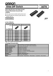
Datasheet - Omron
Datasheet - Omron
Datasheet - Omron

Create successful ePaper yourself
Turn your PDF publications into a flip-book with our unique Google optimized e-Paper software.
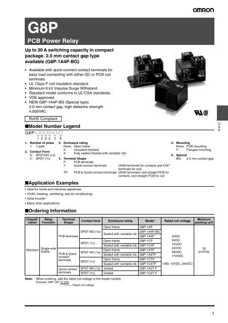
G8P<br />
PCB Power Relay<br />
Up to 30 A switching capacity in compact<br />
package. 2.0 mm cantact gap type<br />
available (G8P-1A4P-BG)<br />
• Available with quick-connect contact terminals for<br />
easy load connecting with either QC or PCB coil<br />
terminals.<br />
• UL Class F coil insulation standard.<br />
• Minimum 6 kV Impulse Surge Withstand.<br />
• Standard model conforms to UL/CSA standards.<br />
• VDE approved.<br />
• NEW G8P-1A4P-BG (Special type)<br />
2.0 mm contact gap, high dielectric strength<br />
4,000VAC.<br />
RoHS Compliant<br />
■Model Number Legend<br />
G8P-@@@@-@-@<br />
— — — — — —<br />
1 2 3 4 5 6<br />
1. Number of poles<br />
1: 1-pole<br />
2. Contact Form<br />
A: SPST-NO (1a)<br />
C: SPDT (1c)<br />
■Application Examples<br />
• Ideal for home and industrial appliances<br />
• HVAC (heating, ventilating, and air conditioning)<br />
• Solar Inverter<br />
• Many other applications<br />
■Ordering Information<br />
3. Enclosure rating<br />
None: Open frame<br />
2: Unsealed (Vented)<br />
4: Fully sealed (Sealed with ventable nib)<br />
4. Terminal Shape<br />
P: PCB terminals<br />
T: Quick-connect terminals (#250 terminals for contacts and #187<br />
terminals for coil)<br />
TP:<br />
PCB & Quick-connect terminals (#250 terminals) and straight PCB for<br />
contacts, and straight PCB for coil<br />
RC<br />
5. Mounting<br />
None: PCB mounting<br />
F: Flanged mounting<br />
6. Special<br />
BG: 2.0 mm contact gap<br />
G<br />
8<br />
P<br />
Classification<br />
Standard<br />
Note:<br />
Relay<br />
Function<br />
Single-side<br />
Stable<br />
Terminal<br />
Shape<br />
PCB terminals<br />
PCB & Quick<br />
connect<br />
terminals<br />
Quick-contact<br />
terminals<br />
When ordering, add the rated coil voltage to the model number.<br />
Example: G8P-1AP 12 VDC<br />
Rated coil voltage<br />
Contact form Enclosure rating Model Rated coil voltage<br />
SPST-NO (1a)<br />
SPDT (1c)<br />
SPST-NO (1a)<br />
SPDT (1c)<br />
Open frame<br />
Sealed with ventable nib<br />
Open frame<br />
Sealed with ventable nib<br />
Open frame<br />
Sealed with ventable nib<br />
Open frame<br />
Sealed with ventable nib<br />
G8P-1AP<br />
G8P-1A4P-BG<br />
G8P-1A4P<br />
G8P-1CP<br />
G8P-1C4P<br />
G8P-1ATP<br />
G8P-1A4TP<br />
G8P-1CTP<br />
G8P-1C4TP<br />
SPST-NO (1a) Vented G8P-1A2T-F<br />
SPDT (1c) Vented G8P-1C2T-F<br />
5VDC<br />
9VDC<br />
12VDC<br />
24VDC<br />
48VDC<br />
110VDC<br />
(-BG: 12VDC, 24VDC)<br />
Minimum<br />
packing unit<br />
50<br />
pcs/tray<br />
1
■Ratings<br />
●Coil<br />
Rated voltage<br />
(VDC)<br />
Note: 1. The rated current and coil resistance are measured at a coil temperature of 23°C with a tolerance of ±10%.<br />
2. The operating characteristics are measured at a coil temperature of 23°C.<br />
3. The “Max. voltage” is the maximum voltage that can be applied to the relay coil.<br />
●Contact<br />
Rated current<br />
(mA)<br />
Coil<br />
resistance<br />
(Ω)<br />
5 185 27<br />
9 93 97<br />
12 77 155<br />
24 36 660<br />
48 19 2,480<br />
110 9 12,400<br />
Must operate voltage<br />
(V)<br />
Must release voltage<br />
(V)<br />
% of rated voltage<br />
Max. voltage<br />
(V)<br />
Power<br />
consumption<br />
(mW)<br />
75% max. 10% min. 120% max. Approx. 900<br />
G<br />
8<br />
P<br />
Load<br />
Resistive load<br />
SPST-NO (1a)<br />
SPDT (1c)<br />
Contact Type<br />
Single<br />
Contact material<br />
Ag-alloy (Cd free)<br />
Rated load<br />
30A at 250VAC (-BG: 20A at 250VAC) 20A/10A (See note.) at 250VAC<br />
20A at 28VDC (-BG: ---- ) 20A/10A (See note.) at 28VDC<br />
Rated carry current 30A (-BG: 20A) 20A/10A (See note.)<br />
Max. switching voltage 250VAC 28VDC (-BG: 250VAC) 250VAC 28VDC<br />
Max. switching current AC30A DC20A (-BG: AC20A) AC20A/10A DC20A/10A (See note.)<br />
Note: NO contact/NC contact<br />
■Characteristics<br />
Item Classification Standard model<br />
Contact resistance *1<br />
Operate time<br />
Release time<br />
Insulation resistance *2<br />
Dielectric strength<br />
Impulse withstand<br />
voltage<br />
Vibration<br />
resistance<br />
Shock resistance<br />
Durability<br />
Note:<br />
Between coil<br />
and contacts<br />
Between<br />
contacts of the<br />
same polarity<br />
Between coil<br />
and contacts<br />
Destruction<br />
Malfunction<br />
100 mΩ max.<br />
15 ms max. (-BG: 20ms max.)<br />
10 ms max.<br />
100 MΩ min. (at 500 VDC)<br />
2,500 VAC, 50/60 Hz for 1 min (-BG: 4,000VAC)<br />
1,500 VAC, 50/60 Hz for 1 min<br />
6,000 V (1.2/50 μs) between coil and contacts<br />
10 to 55 to 10 Hz, 0.825-mm single amplitude (1.65-mm double amplitude) for 2 hours<br />
(-BG: 10 to 55 to 10 Hz, 0.75-mm single amplitude (1.5-mm double amplitude) for 2 hours)<br />
10 to 55 to 10 Hz, 0.825-mm single amplitude (1.65-mm double amplitude) for 5 minutes<br />
Destruction 1,000m/s 2 (approx. 100G)<br />
Malfunction 100 m/s 2 (approx. 10G)<br />
Mechanical 10,000,000 operation min. (at 18,000 operations/hr) (-BG: 5,000,000 operation min.)<br />
Electrical 100,000 operations approx. (at 360 operations/hr) (-BG: 40,000 operation min.)<br />
Ambient operating temperature<br />
-55° to 105°C, cold coil condition (with no icing)<br />
-55° to 85°C, hot coil condition (hot start) (with no icing)<br />
Ambient operating humidity 5% to 85%<br />
Weight<br />
Approx. 24 g to 31g<br />
The data shown above are initial value.<br />
1. Measurement conditions: 5 VDC, 1 A, voltage drop method.<br />
2. Measurement conditions: Measured at the same points as the dielectric strength using a 500 VDC ohmmeter.<br />
2
■Engineering Data<br />
Maximum switching capacity<br />
SPST-NO (1a)<br />
SPDT (1c)<br />
Switching current (A)<br />
AC resistive load<br />
(-BG type)<br />
Switching current (A)<br />
DC resistive<br />
load (NC)<br />
AC resistive load (NO)<br />
AC resistive load (NC)<br />
DC resistive<br />
load (NO)<br />
Durability<br />
SPST-NO (1a)<br />
Durability (x10 3 operations)<br />
Switching voltage (V)<br />
SPDT (1c)<br />
Durability (x10 3 operations)<br />
Switching voltage (V)<br />
G<br />
8<br />
P<br />
Switching current (A)<br />
* Except (-BG) type<br />
Switching current (A)<br />
3
■Dimensions<br />
●Open Frame Types<br />
Unit: mm<br />
G8P-1CP/1AP<br />
Terminal Arrangement/<br />
Internal Connections<br />
(Bottom View)<br />
Mounting Holes (Bottom View)<br />
1.1±0.1 dia. 2.1±0.2 dia.<br />
Note: Pin #4 is omitted on G8P-1AP<br />
G<br />
8<br />
P<br />
G8P-1CTP/1ATP<br />
Terminal Arrangement/<br />
Internal Connections<br />
(Bottom View)<br />
Mounting Holes (Bottom View)<br />
#250 Quick connect<br />
1.1±0.1 dia. 2.1±0.2 dia.<br />
Note: Pin #4 is omitted on G8P-1ATP<br />
4
●Fully-Sealed Types/Unsealed Types<br />
G8P-1C4P/1A4P/1C2P/1A2P<br />
Terminal Arrangement/<br />
Internal Connections<br />
(Bottom View)<br />
Mounting Holes (Bottom View)<br />
1.1±0.1 dia. 2.1±0.2 dia.<br />
Note: Pin #4 is omitted on G8P-1A4P/1A2P<br />
G8P-1C4TP/1A4TP/1C2TP/1A2TP<br />
#250 Quick connect<br />
Terminal Arrangement/<br />
Internal Connections<br />
(Bottom View)<br />
Mounting Holes (Bottom View)<br />
G<br />
8<br />
P<br />
1.1±0.1 dia. 2.1±0.2 dia.<br />
Note: Pin #4 is omitted on G8P-1A4TP/1A2TP<br />
5
●Flange Mounting Types<br />
G8P-1C2T-F/1A2T-F<br />
#250 Quick connect<br />
Terminal Arrangement/Internal<br />
Connections (Bottom View)<br />
Mounting Holes (Bottom View)<br />
#187<br />
Quick<br />
connect<br />
Note: Pin #4 is omitted on G8P-1A2T-F<br />
G<br />
8<br />
P<br />
Note:<br />
Allow air circulation within the sealed type G8P by removing the knock off nib from the cover after soldering and cleaning is complete.<br />
6
■Approved Standards<br />
●UL Recognized (File No. E41643), CSA Certified (File No. LR31928)<br />
Model Contact form Coil ratings Contact ratings Number of test operations<br />
30 A, 240 VAC (G.P./Res.), 40°C 50,000<br />
20 A, 28 VDC (Res.), 40°C 6,000<br />
20 A, 240 VAC (Res.), 70°C<br />
100,000<br />
23 A, 240 VAC (Res.), 85°C<br />
G8P-1AP<br />
G8P-1A4P<br />
1 HP, 125-250 VAC, 40°C<br />
1,000<br />
G8P-1ATP<br />
2 HP, 250 VAC, 40°C<br />
G8P-1A4TP SPST-NO (1a) 5 to 110 VDC<br />
A300 Pilot Duty, 40°C 6,000<br />
G8P-1A2T-F<br />
20 FLA, 96 LRA, 125 VAC, 40°C 100,000<br />
5 A, 250 VAC (Tungsten), 40°C<br />
20 A, 120-277 VAC (Ballast), 40°C<br />
6,000<br />
TV-5, 40°C 25,000<br />
G8P-1A4P-BG 30 A, 277 VAC (Res.), 85°C 30,000<br />
30 A/20 A, 277 VAC (Res.), 40°C<br />
G8P-1CP<br />
G8P-1C4P<br />
G8P-1CTP<br />
G8P-1C4TP<br />
G8P-1C2T-F<br />
SPDT (1c)<br />
5 to 110 VDC<br />
20 A/15 A, 250 VAC (Res.), 105°C<br />
100,000 (N.O.) and 30,000 (N.C.)<br />
20 A/10 A, 28 VDC (Res.), 40°C 6,000<br />
30 A/30 A, 277 VAC (Res.), 40°C 10,000<br />
1/2 HP/1/2 HP, 125 VAC, 40°C 100,000<br />
2 HP/ 1/2 HP, 250 VAC, 40°C<br />
1 HP/ 1/4 HP, 125 VAC, 40°C<br />
1,000<br />
B150 Pilot Duty, 40°C 100,000<br />
5 A/ 3 A, 250 VAC (Tungsten), 40°C<br />
6 A/ 3 A, 277 VAC (Ballast), 40°C<br />
6,000<br />
TV-5 (N.O.), 40°C 25,000<br />
G<br />
8<br />
P<br />
●VDE certified type (Licence No. 40004714)<br />
Note:<br />
1. The rated values approved by each of the safety standards (e.g., UL, CSA) may be different from the performance characteristics<br />
individually defined in this catalog.<br />
2. For information on additional ratings not included in this catalog, contact your local <strong>Omron</strong> Representative.<br />
3. In the interest of product improvement, specifications are subject to change.<br />
4. Please contact <strong>Omron</strong> for details regarding VDE approvals.<br />
5. Meets requirements of polluiton degree 2 with Material II & III.<br />
■Precautions<br />
●Please refer to “PCB Relays Common Precautions” for correct use.<br />
Correct Use<br />
• Regarding the Electrical Appliance and Material Safety Law (Japan)<br />
The G8P series is not compliant with the Electrical Appliance and Material Safety Law. Pay careful attention to select a suitable Relay for<br />
the application.<br />
• Recommended soldering condition<br />
Pre-heat at 120°C maximum within 120 seconds.<br />
Complete soldering at 265°C maximum within 6 seconds.<br />
7
G<br />
8<br />
P<br />
• Application examples provided in this document are for reference only. In actual applications, confirm equipment functions and safety before using the product.<br />
• Consult your OMRON representative before using the product under conditions which are not described in the manual or applying the product to nuclear control systems, railroad<br />
systems, aviation systems, vehicles, combustion systems, medical equipment, amusement machines, safety equipment, and other systems or equipment that may have a serious<br />
influence on lives and property if used improperly. Make sure that the ratings and performance characteristics of the product provide a margin of safety for the system or<br />
equipment, and be sure to provide the system or equipment with double safety mechanisms.<br />
Note: Do not use this document to operate the Unit.<br />
OMRON Corporation<br />
ELECTRONIC AND MECHANICAL COMPONENTS COMPANY Contact: www.omron.com/ecb Cat. No. K040-E1-01<br />
0812(0207)(O)<br />
8