User Manual - Omtec
User Manual - Omtec
User Manual - Omtec

Create successful ePaper yourself
Turn your PDF publications into a flip-book with our unique Google optimized e-Paper software.
NEXCOM International Co., Ltd.<br />
Multi-Media Solutions<br />
Digital Signage Platform<br />
NDiS 166<br />
<strong>User</strong> <strong>Manual</strong><br />
NEXCOM International Co., Ltd.<br />
Published January 2011<br />
www.nexcom.com
Contents<br />
Contents<br />
Preface<br />
Copyright .............................................................................................. iv<br />
Disclaimer .............................................................................................. iv<br />
Acknowledgements ............................................................................... iv<br />
Regulatory Compliance Statements ........................................................ iv<br />
Safety Information .................................................................................vii<br />
Package Contents<br />
Ordering Information<br />
Chapter 1: Product Introduction<br />
Overview.................................................................................................1<br />
Key Features............................................................................................1<br />
Physical Features......................................................................................2<br />
Hardware Specifications...........................................................................3<br />
System.....................................................................................................3<br />
Main Board..............................................................................................5<br />
Mechanical Dimensions............................................................................7<br />
Chapter 2: Jumpers and Connectors<br />
Before You Begin ....................................................................................8<br />
Precautions .............................................................................................9<br />
Jumper Settings.....................................................................................10<br />
Locations of the Jumpers and Connectors..............................................11<br />
External Connectors Pin Definitions........................................................12<br />
Power Input Connector.....................................................................12<br />
ATX Power Switch.............................................................................12<br />
HDMI Type A Connector....................................................................13<br />
VGA Connector.................................................................................13<br />
DVI-I Connector................................................................................14<br />
S/PDIF Connector..............................................................................14<br />
Audio Jack........................................................................................15<br />
LAN connector..................................................................................15<br />
USB Port............................................................................................16<br />
RS232 Port........................................................................................16<br />
LED HDD/PWR ..................................................................................17<br />
Internal Connectors Pin Definitions........................................................18<br />
Serial-ATA ........................................................................................18<br />
Serial-ATA ........................................................................................18<br />
USB Connector..................................................................................19<br />
Serial-ATA DOM Power......................................................................19<br />
Mini-PCIe..........................................................................................20<br />
IRDA Connector ...............................................................................20<br />
FAN Connector..................................................................................21<br />
Reset Connector................................................................................21<br />
CMOS Clear Select............................................................................21<br />
ME Clear Select.................................................................................21<br />
GPIO.................................................................................................22<br />
Copyright © 2011 NEXCOM International Co., Ltd. All Rights Reserved. ii NDiS 166 <strong>User</strong> <strong>Manual</strong>
Contents<br />
Chapter 3: System Setup<br />
Removing the Chassis Cover..................................................................23<br />
Installing a DIMM...................................................................................24<br />
Installing the CPU..................................................................................26<br />
Installing a SATA Hard Drive...................................................................30<br />
Installing a Wireless LAN Module...........................................................34<br />
Installing a TV Tuner Module..................................................................38<br />
Chapter 4: BIOS Setup<br />
About BIOS Setup..................................................................................42<br />
When to Configure the BIOS..................................................................42<br />
Default Configuration ...........................................................................43<br />
Entering Setup.......................................................................................43<br />
Legends.................................................................................................43<br />
Scroll Bar ..............................................................................................44<br />
BIOS Setup Utility...................................................................................44<br />
Main .....................................................................................................45<br />
Advanced..............................................................................................46<br />
CPU Configuration.................................................................................48<br />
SATA Configuration...............................................................................49<br />
Anti-Thefts Configuration......................................................................50<br />
AMT Configuration................................................................................51<br />
USB Configuration.................................................................................52<br />
Super IO Configuration .........................................................................53<br />
H/W Monitor.........................................................................................54<br />
Chipset..................................................................................................55<br />
System Agent (SA) Configuration...........................................................56<br />
INTEL IGFX Configuration.......................................................................57<br />
PCH-IO Configuration............................................................................58<br />
Boot .....................................................................................................59<br />
Security..................................................................................................60<br />
Save & Exit.............................................................................................61<br />
Chapter 5: AMT Settings<br />
Enable Intel® AMT in the AMI BIOS.......................................................66<br />
Configure the Intel® ME Setup..............................................................67<br />
Unconfigure AMT/ME............................................................................85<br />
Appendix A: Watchdog Timer<br />
Appendix B: GPI/O Programming Guide<br />
Copyright © 2011 NEXCOM International Co., Ltd. All Rights Reserved. iii NDiS 166 <strong>User</strong> <strong>Manual</strong>
Preface<br />
Preface<br />
Copyright<br />
This publication, including all photographs, illustrations and software, is<br />
protected under international copyright laws, with all rights reserved. No<br />
part of this manual may be reproduced, copied, translated or transmitted<br />
in any form or by any means without the prior written consent from<br />
NEXCOM International Co., Ltd.<br />
Disclaimer<br />
The information in this document is subject to change without prior notice<br />
and does not represent commitment from NEXCOM International Co., Ltd.<br />
However, users may update their knowledge of any product in use by constantly<br />
checking its manual posted on our website: http://www.nexcom.<br />
com. NEXCOM shall not be liable for direct, indirect, special, incidental, or<br />
consequential damages arising out of the use of any product, nor for any<br />
infringements upon the rights of third parties, which may result from such<br />
use. Any implied warranties of merchantability or fitness for any particular<br />
purpose is also disclaimed.<br />
Acknowledgements<br />
NDiS 166 is a trademark of NEXCOM International Co., Ltd. All other product<br />
names mentioned herein are registered trademarks of their respective<br />
owners.<br />
Regulatory Compliance Statements<br />
This section provides the FCC compliance statement for Class A devices<br />
and describes how to keep the system CE compliant.<br />
Declaration of Conformity<br />
FCC<br />
This equipment has been tested and verified to comply with the limits for<br />
a Class A digital device, pursuant to Part 15 of FCC Rules. These limits are<br />
designed to provide reasonable protection against harmful interference<br />
when the equipment is operated in a commercial environment. This equipment<br />
generates, uses, and can radiate radio frequency energy and, if not<br />
installed and used in accordance with the instructions, may cause harmful<br />
interference to radio communications. Operation of this equipment in a<br />
residential area (domestic environment) is likely to cause harmful interference,<br />
in which case the user will be required to correct the interference<br />
(take adequate measures) at their own expense.<br />
CE<br />
The product(s) described in this manual complies with all applicable European<br />
Union (CE) directives if it has a CE marking. For computer systems to<br />
remain CE compliant, only CE-compliant parts may be used. Maintaining<br />
CE compliance also requires proper cable and cabling techniques.<br />
Copyright © 2011 NEXCOM International Co., Ltd. All Rights Reserved. iv NDiS 166 <strong>User</strong> <strong>Manual</strong>
Preface<br />
RoHS Compliance<br />
NEXCOM RoHS Environmental Policy and Status<br />
Update<br />
NEXCOM is a global citizen for building the digital<br />
infrastructure. We are committed to providing green<br />
products and services, which are compliant with European<br />
Union RoHS (Restriction on Use of Hazardous Substance in Electronic<br />
Equipment) directive 2002/95/EU, to be your trusted green partner and to<br />
protect our environment.<br />
RoHS restricts the use of Lead (Pb) < 0.1% or 1,000ppm, Mercury (Hg)<br />
< 0.1% or 1,000ppm, Cadmium (Cd) < 0.01% or 100ppm, Hexavalent<br />
Chromium (Cr6+) < 0.1% or 1,000ppm, Polybrominated biphenyls (PBB)<br />
< 0.1% or 1,000ppm, and Polybrominated diphenyl Ethers (PBDE) < 0.1%<br />
or 1,000ppm.<br />
In order to meet the RoHS compliant directives, NEXCOM has established<br />
an engineering and manufacturing task force in to implement the introduction<br />
of green products. The task force will ensure that we follow the<br />
standard NEXCOM development procedure and that all the new RoHS<br />
components and new manufacturing processes maintain the highest<br />
industry quality levels for which NEXCOM are renowned.<br />
The model selection criteria will be based on market demand. Vendors and<br />
suppliers will ensure that all designed components will be RoHS compliant.<br />
How to recognize NEXCOM RoHS Products?<br />
For existing products where there are non-RoHS and RoHS versions, the<br />
suffix “(LF)” will be added to the compliant product name.<br />
All new product models launched after January 2006 will be RoHS compliant.<br />
They will use the usual NEXCOM naming convention.<br />
Copyright © 2011 NEXCOM International Co., Ltd. All Rights Reserved. v NDiS 166 <strong>User</strong> <strong>Manual</strong>
Preface<br />
Warranty and RMA<br />
NEXCOM Warranty Period<br />
NEXCOM manufactures products that are new or equivalent to new in<br />
accordance with industry standard. NEXCOM warrants that products will<br />
be free from defect in material and workmanship for 2 years, beginning<br />
on the date of invoice by NEXCOM. HCP series products (Blade Server)<br />
which are manufactured by NEXCOM are covered by a three year warranty<br />
period.<br />
NEXCOM Return Merchandise Authorization (RMA)<br />
??<br />
Customers shall enclose the “NEXCOM RMA Service Form” with the<br />
returned packages.<br />
??<br />
Customers must collect all the information about the problems encountered<br />
and note anything abnormal or, print out any on-screen messages,<br />
and describe the problems on the “NEXCOM RMA Service Form” for<br />
the RMA number apply process.<br />
??<br />
Customers can send back the faulty products with or without accessories<br />
(manuals, cable, etc.) and any components from the card, such as<br />
CPU and RAM. If the components were suspected as part of the problems,<br />
please note clearly which components are included. Otherwise,<br />
NEXCOM is not responsible for the devices/parts.<br />
??<br />
Customers are responsible for the safe packaging of defective products,<br />
making sure it is durable enough to be resistant against further damage<br />
and deterioration during transportation. In case of damages occurred<br />
during transportation, the repair is treated as “Out of Warranty.”<br />
??<br />
Any products returned by NEXCOM to other locations besides the customers’<br />
site will bear an extra charge and will be billed to the customer.<br />
Repair Service Charges for Out-of-Warranty Products<br />
NEXCOM will charge for out-of-warranty products in two categories, one<br />
is basic diagnostic fee and another is component (product) fee.<br />
System Level<br />
??<br />
Component fee: NEXCOM will only charge for main components such<br />
as SMD chip, BGA chip, etc. Passive components will be repaired for<br />
free, ex: resistor, capacitor.<br />
??<br />
Items will be replaced with NEXCOM products if the original one cannot<br />
be repaired. Ex: motherboard, power supply, etc.<br />
??<br />
Replace with 3rd party products if needed.<br />
??<br />
If RMA goods can not be repaired, NEXCOM will return it to the customer<br />
without any charge.<br />
Board Level<br />
??<br />
Component fee: NEXCOM will only charge for main components, such<br />
as SMD chip, BGA chip, etc. Passive components will be repaired for<br />
free, ex: resistors, capacitors.<br />
? ? If RMA goods can not be repaired, NEXCOM will return it to the customer<br />
without any charge.<br />
Copyright © 2011 NEXCOM International Co., Ltd. All Rights Reserved. vi NDiS 166 <strong>User</strong> <strong>Manual</strong>
Preface<br />
Warnings<br />
Read and adhere to all warnings, cautions, and notices in this guide and<br />
the documentation supplied with the chassis, power supply, and accessory<br />
modules. If the instructions for the chassis and power supply are inconsistent<br />
with these instructions or the instructions for accessory modules,<br />
contact the supplier to find out how you can ensure that your computer<br />
meets safety and regulatory requirements.<br />
Cautions<br />
Electrostatic discharge (ESD) can damage system components. Do the described<br />
procedures only at an ESD workstation. If no such station is available,<br />
you can provide some ESD protection by wearing an antistatic wrist<br />
strap and attaching it to a metal part of the computer chassis.<br />
Safety Information<br />
Before installing and using the device, note the following precautions:<br />
▪▪<br />
Read all instructions carefully.<br />
▪▪<br />
Do not place the unit on an unstable surface, cart, or stand.<br />
▪▪<br />
Follow all warnings and cautions in this manual.<br />
▪▪<br />
When replacing parts, ensure that your service technician uses parts<br />
specified by the manufacturer.<br />
▪▪<br />
Avoid using the system near water, in direct sunlight, or near a heating<br />
device.<br />
▪▪<br />
The load of the system unit does not solely rely for support from the<br />
rackmounts located on the sides. Firm support from the bottom is highly<br />
necessary in order to provide balance stability.<br />
▪▪<br />
The computer is provided with a battery-powered real-time clock circuit.<br />
There is a danger of explosion if battery is incorrectly replaced. Replace<br />
only with the same or equivalent type recommended by the manufacturer.<br />
Discard used batteries according to the manufacturer’s instructions.<br />
Installation Recommendations<br />
Ensure you have a stable, clean working environment. Dust and dirt can<br />
get into components and cause a malfunction. Use containers to keep<br />
small components separated.<br />
Adequate lighting and proper tools can prevent you from accidentally<br />
damaging the internal components. Most of the procedures that follow<br />
require only a few simple tools, including the following:<br />
• A Philips screwdriver<br />
• A flat-tipped screwdriver<br />
• A grounding strap<br />
• An anti-static pad<br />
Using your fingers can disconnect most of the connections. It is recommended<br />
that you do not use needlenose pliers to disconnect connections<br />
as these can damage the soft metal or plastic parts of the connectors.<br />
Copyright © 2011 NEXCOM International Co., Ltd. All Rights Reserved. vii NDiS 166 <strong>User</strong> <strong>Manual</strong>
Preface<br />
Safety Precautions<br />
1. Read these safety instructions carefully.<br />
2. Keep this <strong>User</strong> <strong>Manual</strong> for later reference.<br />
3. Disconnect this equipment from any AC outlet before cleaning. Use a<br />
damp cloth. Do not use liquid or spray detergents for cleaning.<br />
4. For plug-in equipment, the power outlet socket must be located near<br />
the equipment and must be easily accessible.<br />
5. Keep this equipment away from humidity.<br />
6. Put this equipment on a stable surface during installation. Dropping<br />
it or letting it fall may cause damage.<br />
7. Do not leave this equipment in either an unconditioned environment<br />
or in a above 40 o C storage temperature as this may damage the<br />
equipment.<br />
8. The openings on the enclosure are for air convection to protect the<br />
equipment from overheating. DO NOT COVER THE OPENINGS.<br />
9. Make sure the voltage of the power source is correct before connecting<br />
the equipment to the power outlet.<br />
10. Place the power cord in a way so that people will not step on it. Do<br />
not place anything on top of the power cord. Use a power cord that<br />
has been approved for use with the product and that it matches the<br />
voltage and current marked on the product’s electrical range label.<br />
The voltage and current rating of the cord must be greater than the<br />
voltage and current rating marked on the product.<br />
11. All cautions and warnings on the equipment should be noted.<br />
12. If the equipment is not used for a long time, disconnect it from the<br />
power source to avoid damage by transient overvoltage.<br />
13. Never pour any liquid into an opening. This may cause fire or electrical<br />
shock.<br />
14. Never open the equipment. For safety reasons, the equipment should<br />
be opened only by qualified service personnel.<br />
15. If one of the following situations arises, get the equipment checked<br />
by service personnel:<br />
a. The power cord or plug is damaged.<br />
b. Liquid has penetrated into the equipment.<br />
c. The equipment has been exposed to moisture.<br />
d. The equipment does not work well, or you cannot get it to work<br />
according to the user’s manual.<br />
e. The equipment has been dropped and damaged.<br />
f. The equipment has obvious signs of breakage.<br />
16. Do not place heavy objects on the equipment.<br />
17. The unit uses a three-wire ground cable which is equipped with a<br />
third pin to ground the unit and prevent electric shock. Do not defeat<br />
the purpose of this pin. If your outlet does not support this kind of<br />
plug, contact your electrician to replace your obsolete outlet.<br />
18. CAUTION: DANGER OF EXPLOSION IF BATTERY IS INCORRECTLY<br />
REPLACED. REPLACE ONLY WITH THE SAME OR EQUIVALENT TYPE<br />
RECOMMENDED BY THE MANUFACTURER. DISCARD USED BATTER-<br />
IES ACCORDING TO THE MANUFACTURER’S INSTRUCTIONS.<br />
19. The computer is provided with CD drives that comply with the appropriate<br />
safety standards including IEC 60825.<br />
Copyright © 2011 NEXCOM International Co., Ltd. All Rights Reserved. viii NDiS 166 <strong>User</strong> <strong>Manual</strong>
Preface<br />
Technical Support and Assistance<br />
Conventions Used in this <strong>Manual</strong><br />
1. For the most updated information of NEXCOM products, visit NEX-<br />
COM’s website at www.nexcom.com.<br />
2. For technical issues that require contacting our technical support team<br />
or sales representative, please have the following information ready<br />
before calling:<br />
– Product name and serial number<br />
– Detailed information of the peripheral devices<br />
– Detailed information of the installed software (operating system,<br />
version, application software, etc.)<br />
– A complete description of the problem<br />
– The exact wordings of the error messages<br />
Warning!<br />
1. Handling the unit: carry the unit with both hands and handle it with<br />
care.<br />
2. Maintenance: to keep the unit clean, use only approved cleaning products<br />
or clean with a dry cloth.<br />
3. CompactFlash: Turn off the unit’s power before inserting or removing a<br />
CompactFlash storage card.<br />
CAUTION!<br />
Warning: Information about certain situations, which if not<br />
observed, can cause personal injury. This will prevent injury to<br />
yourself when performing a task.<br />
Caution: Information to avoid damaging components or losing<br />
data.<br />
Note: Provides additional information to complete a task easily.<br />
Copyright © 2011 NEXCOM International Co., Ltd. All Rights Reserved. ix NDiS 166 <strong>User</strong> <strong>Manual</strong>
Preface<br />
Global Service Contact Information<br />
Headquarters<br />
Taiwan<br />
18F, No. 716, Chung-Cheng Rd., Chung-Ho Dist.,<br />
New Taipei City, 235, Taiwan, R.O .C.<br />
Tel: +886-2-8228-0606<br />
Fax: +886-2-8228-0501<br />
http://www.nexcom.com.tw<br />
USA<br />
3758 Spinnaker Court Fremont,<br />
CA, 94538, USA<br />
Tel: +1-510-656-2248<br />
Fax: +1-510-656-2158<br />
http://www.nexcom.com<br />
France<br />
Z.I. des Amandiers<br />
17, Rue des entrepreneurs,<br />
78420 Carrières sur Seine, France<br />
Tel: +33 (0)1 71 51 10 20<br />
Fax: +33 (0)1 71 51 10 21<br />
http://www.nexcom.eu<br />
Germany<br />
Leopoldstraße Business Centre,<br />
Leopoldstraße 244,<br />
80807 Munich, Germany<br />
Tel: +49-89-208039-278<br />
Fax: +49-89-208039-279<br />
http://www.nexcom.eu<br />
Italy<br />
Via Gaudenzio Ferrari 29,<br />
21047 Saronno (VA), Italia<br />
Tel: +39 02 9628 0333<br />
Fax: +39 02 9619 8846<br />
http://www.nexcom.eu<br />
United Kingdom<br />
10 Vincent Avenue,<br />
Crownhill Business Centre,<br />
Milton Keynes, Buckinghamshire<br />
MK8 0AB, United Kingdom<br />
Tel: +44-1908-267121<br />
Fax: +44-1908-262042<br />
http://www.nexcom.eu<br />
Copyright © 2011 NEXCOM International Co., Ltd. All Rights Reserved. x NDiS 166 <strong>User</strong> <strong>Manual</strong>
Preface<br />
China-Beijing<br />
Room 301, Block E, Power Creative Bldg.,<br />
No.1 Shangdi East Rd., Haidian Dist.,<br />
Beijing, 100085, China<br />
Tel: +86-10-5885-6655<br />
Fax: +86-10-5885-1066<br />
http://www.nexcom.cn<br />
Japan<br />
9F, Tamachi Hara Bldg.,<br />
4-11-5, Shiba Minato-ku,<br />
Tokyo, 108-0014, Japan<br />
Tel: +81-3-5419-7830<br />
Fax: +81-3-5419-7832<br />
http://www.nexcom-jp.com<br />
China-Shanghai Office<br />
Room 1505, Greenland He Chuang Bldg.,<br />
No. 450 Caoyang Rd.,<br />
Shanghai, 200062, China<br />
Tel: +86-21-6150-8008<br />
Fax: +86-21-3251-6358<br />
http://www.nexcom.cn<br />
China-Nanjing Office<br />
Hall C, Block 17, Tian Xing Cui Lang Bldg.,<br />
No. 49 Yunnan North Rd.,<br />
Nanjing, 210018, China<br />
Tel: +86-25-8315-3486<br />
Fax: +86-25-8315-3489<br />
http://www.nexcom.cn<br />
China-Shenzhen Office<br />
Western Room 708, Block 210,<br />
Tairan Industry & Trading Place, Futian Area,<br />
Shenzhen, 518040, China<br />
TEL: +86-755-833 27203<br />
FAX: +86-755-833 27213<br />
http://www.nexcom.cn<br />
Copyright © 2011 NEXCOM International Co., Ltd. All Rights Reserved. xi NDiS 166 <strong>User</strong> <strong>Manual</strong>
Preface<br />
Package Contents<br />
Before continuing, verify that the NDiS 166 package that you received is complete. Your NDiS 166 package should have all the items listed in the following<br />
table.<br />
Item P/N Name Specification Qty<br />
1 5044440080X00 GASKET FOR INTEL CPU KGS:C-4505(35x35x1)+G4000 35x35x 1.1mm 1<br />
2 7400096003X00 (N)POWER ADAPTER FSP:FSP096-AHA 96W 12V/ 8A MINI DIN 4P 1<br />
3 50311F0100X00 ROUND HEAD SCREW W/SPRING+FLAT WASHER LONG x4 P3x6 iso/SW6x0.5 NI 1<br />
4 602DCD0306X00 (N)NDiS166 MANUAL DRIVER CD 1<br />
Copyright © 2011 NEXCOM International Co., Ltd. All Rights Reserved. xii NDiS 166 <strong>User</strong> <strong>Manual</strong>
Preface<br />
Ordering Information<br />
The following provides ordering information for NDiS 166.<br />
• NDiS 166 (P/N: TBD)<br />
- Intel® Core i5/i7 series processors<br />
- Intel® QM67<br />
- Intel® Integrated Graphics<br />
Copyright © 2011 NEXCOM International Co., Ltd. All Rights Reserved. xiii NDiS 166 <strong>User</strong> <strong>Manual</strong>
Chapter 1: Product Introduction<br />
Chapter 1: Product Introduction<br />
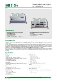
Overview<br />
NDiS 166 is specially designed to be mounted behind the large-size display<br />
device such as LCD TV or PDP. NDiS 166 supports dual display output<br />
by DVI, HDMI or VGA. The NDiS 166 operates on Intel® Core i5/i7<br />
series processors with QM67 integrated graphics controller. NDiS 166 can<br />
smoothly playback dual Full HD video. NDiS 166 is ideal as advanced digital<br />
signage player for advertising, hospitality, brand promotion and digital<br />
menu board application.<br />
Key Features<br />
▪▪<br />
2nd Generation Intel® Core i5/i7 Series Platform<br />
▪▪<br />
Compact and Fan-Less Design<br />
▪<br />
▪ Up to 16GB with un-buffered and Non-ECC DDR3 1066/1333 MHz<br />
SDRAM<br />
▪▪<br />
Intel® Integrated Graphics Engine<br />
▪▪<br />
Dual Independent Display Supported<br />
▪▪<br />
Intel WG82579LM Gigabit Ethernet controller<br />
▪▪<br />
Two Mini-PCIe<br />
Copyright © 2011 NEXCOM International Co., Ltd. All Rights Reserved. 1 NDiS 166 <strong>User</strong> <strong>Manual</strong>
Chapter 1: Product Introduction<br />
Physical Features<br />
Front panel<br />
Side panel<br />
HDD LED<br />
VGA<br />
USB<br />
S/PDIF<br />
Line-in<br />
USB<br />
COM<br />
Power<br />
LED<br />
Power<br />
Button<br />
12V DC-in<br />
DVI-D<br />
HDMI<br />
LAN<br />
Line-out<br />
Copyright © 2011 NEXCOM International Co., Ltd. All Rights Reserved. 2 NDiS 166 <strong>User</strong> <strong>Manual</strong>
Chapter 1: Product Introduction<br />
Hardware Specifications<br />
System<br />
Processor<br />
▪▪<br />
Quad Core: Intel® CoreTM i7-2710QE processor 2.1 GHz, 45W (system<br />
with cooler)<br />
▪▪<br />
Dual Core: Intel® CoreTM i5-2510E processor 2.5 GHz, 35W (fanless)<br />
▪▪<br />
FSB<br />
- 1066/1333 MHz<br />
Chipset<br />
▪▪<br />
Intel® QM67 PCH<br />
Main Memory<br />
▪▪<br />
Two 240-pin 25°angled DDR3 DIMM sockets<br />
▪▪<br />
DDR3 1066/1333 MHz SDRAM with un-buffered and Non-ECC memory<br />
module<br />
▪▪<br />
Support up to 16GB memory<br />
▪▪<br />
Analog CRT<br />
- DB15 connector<br />
- Integrated 300MHz DAC<br />
- Analog monitor supports up to QXGA<br />
- Supports CRT Hot-Plug<br />
▪▪<br />
DVI<br />
- External DVI-D interface<br />
- TMDS transmitter via SDVO interface<br />
▪▪<br />
HDMI<br />
Integrated HDMI (iHDMI)<br />
- Video support for CEA modes 480i/p, 576i/p, 720p, 1080i/p and PC<br />
modes though dot clock<br />
- Intel HD Audio support<br />
- Integrated Intel HD Audio codec<br />
- Dolby* AC3 compress, Dolby* Digital, Dolby* DTS (full support)<br />
- PCM audio support<br />
▪▪<br />
Dual Display<br />
- Dual independent display: CRT+HDMI<br />
- Dual independent display: DVI+HDMI<br />
- Dual independent display: DVI+CRT<br />
Graphics<br />
▪▪<br />
Graphics chip<br />
- Intel HD integrated graphic<br />
- Intel® Dynamic Video Memory Technology<br />
- Image Rotate by driver support<br />
Copyright © 2011 NEXCOM International Co., Ltd. All Rights Reserved. 3 NDiS 166 <strong>User</strong> <strong>Manual</strong>
Chapter 1: Product Introduction<br />
Network<br />
▪▪<br />
Intel® WG82579LM GbE controller<br />
▪▪<br />
Intel® 82574 GbE Controller<br />
▪<br />
▪▪<br />
Support WOL<br />
▪▪<br />
2 x RJ45 connector with LEDs<br />
▪<br />
▪ PXE LAN boot ROM for Ethernet Boot up.<br />
▪ Support Intel® Active Management Technology 7.0 support<br />
Storage<br />
▪▪<br />
One JST 2.54mm 4-pin power connector for SATA device<br />
▪▪<br />
One 7-pin SATA connector<br />
▪▪<br />
One SATA + Power 90° connector<br />
▪▪<br />
One 2.5” HDD drive bay<br />
Audio<br />
▪▪<br />
Audio 1<br />
- ALC 888 HD codec<br />
- Speaker-out with amplifying feature (1W, 8ohm)<br />
- One audio jack for analog input (programmable as analog output)<br />
- One SPDIF for digital output<br />
▪▪<br />
Audio 2<br />
- HDMI for PCM audio output<br />
I/O Interfaces<br />
▪▪<br />
Serial<br />
- DB9 COM 1 (RS232) connector at the front panel<br />
- DB9 COM 2 (RS232) connector at the front panel<br />
▪▪<br />
USB<br />
- USB 2.0 ports 1~2 at the rear panel<br />
- USB 2.0 ports 3~4 at the front panel<br />
- USB 2.0 Port 5~6 reserved, JST<br />
- USB 2.0 Port 7 to mini-PCIe<br />
- USB 2.0 Port 8 to mini-PCIe<br />
▪▪<br />
GPIO<br />
- 8 GPIO lines (GPI 0~3 and GPO 0~3); TTL Level (0/5V)<br />
- One Power button trigger<br />
- One Sleep button trigger<br />
- 2x6 pin header, 2.54mm<br />
▪▪<br />
Others<br />
- OnBoard buzzer<br />
- RTC reset: 1x3 pin header, 2.54mm<br />
- IR interface: 1x5 pin header, 2.54mm<br />
- Reset: 1x2 pin header, 2.54mm<br />
Copyright © 2011 NEXCOM International Co., Ltd. All Rights Reserved. 4 NDiS 166 <strong>User</strong> <strong>Manual</strong>
Chapter 1: Product Introduction<br />
Power Supply<br />
▪▪<br />
Onboard DC to DC<br />
- Power range design: +12V +/-10% DC input<br />
- 4-pin Mini-DIN power jack<br />
- ATX power mode<br />
- Supports wake up alarm<br />
- Supports WOL<br />
- Support power on after failure<br />
- Support soft off<br />
▪▪<br />
External adapter<br />
- +12V DC output 96W<br />
RTC Battery<br />
▪▪<br />
On chip RTC with battery back up / One External Li-ion Battery<br />
▪▪<br />
RTC tolerance less than 2sec (24 hours) under 25°C environment<br />
BIOS<br />
▪▪<br />
AMI system BIOS<br />
▪▪<br />
SPI 6416Mbits flash ROM<br />
▪▪<br />
Support Intel AMT 7.0<br />
System Management<br />
▪▪<br />
Monitoring<br />
- Super IO built-in function (IT8728F)<br />
- Monitoring of 5 voltages, 3 temperature<br />
4 voltage (For +3.3V, +5V, +12V, Vcore)<br />
3 Temperatures (CPU, two external Temperature Sensor)<br />
Two FAN 3-pin connectors<br />
▪▪<br />
Watchdog<br />
- Watchdog timeout is programmable by software from 1 second to 255<br />
seconds and from 1 minute to 255 minutes<br />
- Tolerance: 15% under room temperature 25°C<br />
Operating System Support<br />
▪▪<br />
Microsoft<br />
- XP / Vista / Windows 7 / WES2009 / WES7<br />
Main Board<br />
External I/O<br />
▪▪<br />
Front I/O<br />
- Two USB 2.0 ports<br />
- Two RS232 COM ports<br />
- Power Button<br />
- One power LED (green)<br />
- One HDD LED (red)<br />
- On/Off switch<br />
Copyright © 2011 NEXCOM International Co., Ltd. All Rights Reserved. 5 NDiS 166 <strong>User</strong> <strong>Manual</strong>
Chapter 1: Product Introduction<br />
▪▪<br />
Rear I/O<br />
- One audio-out port<br />
- One audio-in port<br />
- One SPDIF port<br />
- Two USB 2.0 ports<br />
- Two RJ45 Gigabit LAN ports<br />
- One HDMI port<br />
- One DVI-D port<br />
- One VGA port<br />
- +12V DC-in jack<br />
Environment<br />
▪▪<br />
Operating temperature: 100% CPU loading and component thermal<br />
profile: 0 ~ 40 °C<br />
▪▪<br />
Storage temperature: -40°C ~ 80°C<br />
▪▪<br />
Relative humidity (non-condensing): 95%<br />
Certificate<br />
▪▪<br />
CE<br />
▪▪<br />
FCC Class A<br />
Physical Characteristics<br />
▪▪<br />
Dimensions (W x D x H)<br />
- 250mm x 194mm x 40mm (without bracket)<br />
▪▪<br />
Color<br />
- Black<br />
▪▪<br />
Mounting<br />
- Wall mount bracket<br />
- VESA mount<br />
▪▪<br />
Cooling system<br />
- Fanless<br />
Expansion<br />
▪▪<br />
Two Mini-PCIe slots<br />
▪▪<br />
Supports Wireless LAN module & DVB-T TV-tuner module<br />
▪▪<br />
Support wake on WLAN feature<br />
Copyright © 2011 NEXCOM International Co., Ltd. All Rights Reserved. 6 NDiS 166 <strong>User</strong> <strong>Manual</strong>
Chapter 1: Product Introduction<br />
Mechanical Dimensions<br />
<br />
<br />
<br />
<br />
<br />
<br />
<br />
<br />
<br />
<br />
<br />
<br />
Copyright © 2011 NEXCOM International Co., Ltd. All Rights Reserved. 7 NDiS 166 <strong>User</strong> <strong>Manual</strong>
Chapter 2: Jumpers and Connectors<br />
Chapter 2: Jumpers and Connectors<br />
This chapter describes how to set the jumpers on the motherboard. Note<br />
that the following procedures are generic for all NDiS 166 series.<br />
Before You Begin<br />
▪▪<br />
Ensure you have a stable, clean working environment. Dust and dirt can<br />
get into components and cause a malfunction. Use containers to keep<br />
small components separated.<br />
▪▪<br />
Before working on internal components, make sure that the poweris off.<br />
Ground yourself before touching any internal components, by touching<br />
a metal object. Static electricity can damage many of the electronic<br />
components. Humid environment tend to have less static electricity<br />
▪▪<br />
than dry environments. A grounding strap is warranted whenever<br />
danger of static electricity exists.<br />
▪▪<br />
Adequate lighting and proper tools can prevent you from accidentally<br />
damaging the internal components. Most of the procedures that follow<br />
require only a few simple tools, including the following:<br />
--<br />
A Philips screwdriver<br />
--<br />
A flat-tipped screwdriver<br />
--<br />
A set of jewelers Screwdrivers<br />
--<br />
A grounding strap<br />
--<br />
An anti-static pad<br />
▪▪<br />
Using your fingers can disconnect most of the connections. It is<br />
recommended that you do not use needle-nosed pliers to disconnect<br />
connections as these can damage the soft metal or plastic parts of the<br />
connectors.<br />
Copyright © 2011 NEXCOM International Co., Ltd. All Rights Reserved. 8 NDiS 166 <strong>User</strong> <strong>Manual</strong>
Chapter 2: Jumpers and Connectors<br />
Precautions<br />
Computer components and electronic circuit boards can be damaged by<br />
discharges of static electricity. Working on the computers that are still<br />
connected to a power supply can be extremely dangerous.<br />
Follow the guidelines below to avoid damage to your computer or yourself:<br />
▪▪<br />
Always disconnect the unit from the power outlet whenever you are<br />
working inside the case.<br />
▪▪<br />
If possible, wear a grounded wrist strap when you are working inside<br />
the computer case. Alternatively, discharge any static electricity by<br />
touching the bare metal chassis of the unit case, or the bare metal body<br />
of any other grounded appliance.<br />
▪▪<br />
Hold electronic circuit boards by the edges only. Do not touch the<br />
components on the board unless it is necessary to do so. Don’t flex or<br />
stress the circuit board.<br />
▪▪<br />
Leave all components inside the static-proof packaging that they<br />
shipped with until they are ready for installation.<br />
▪▪<br />
Use correct screws and do not over tighten screws.<br />
Copyright © 2011 NEXCOM International Co., Ltd. All Rights Reserved. 9 NDiS 166 <strong>User</strong> <strong>Manual</strong>
Chapter 2: Jumpers and Connectors<br />
Jumper Settings<br />
A jumper is the simplest kind of electric switch. It consists of two metal<br />
pins and a cap. When setting the jumpers, ensure that the jumper caps are<br />
placed on the correct pins. When the jumper cap is placed on both pins,<br />
the jumper is short. If you remove the jumper cap, or place the jumper<br />
cap on just one pin, the jumper is open.<br />
Refer to the illustrations below for examples of what the 2-pin and 3-pin<br />
jumpers look like when they are short (on) and open (off).<br />
Two-Pin Jumpers: Open (Left) and Short (Right)<br />
Three-Pin Jumpers: Pins 1 and 2 Are Short<br />
1<br />
2<br />
3<br />
1<br />
2<br />
3<br />
Copyright © 2011 NEXCOM International Co., Ltd. All Rights Reserved. 10 NDiS 166 <strong>User</strong> <strong>Manual</strong>
Chapter 2: Jumpers and Connectors<br />
Locations of the Jumpers and Connectors<br />
NDiB 166<br />
The figure on the right is the NDiB 166 motherboard which is the motherboard used in the NDiS 166 system. It shows the locations of the jumpers and connectors.<br />
Copyright © 2011 NEXCOM International Co., Ltd. All Rights Reserved. 11 NDiS 166 <strong>User</strong> <strong>Manual</strong>
Chapter 2: Jumpers and Connectors<br />
External Connectors Pin Definitions<br />
This section provides descriptions, illustrations and pin definitions of the<br />
external connectors.<br />
Connector Specification<br />
Power Input Connector<br />
CN1 (4-pin power jack with lock)<br />
ATX Power Switch<br />
SW1 (push button with LED and without lock)<br />
1 2<br />
Status<br />
Standby<br />
Operation<br />
LED Color<br />
Red<br />
Blue<br />
3 4<br />
Pin<br />
Definition<br />
1 DC-IN (+12VSB)<br />
2 DC-IN (+12VSB)<br />
3 GND<br />
4 GND<br />
Copyright © 2011 NEXCOM International Co., Ltd. All Rights Reserved. 12 NDiS 166 <strong>User</strong> <strong>Manual</strong>
Chapter 2: Jumpers and Connectors<br />
HDMI Type A Connector<br />
J6<br />
VGA Connector<br />
VGA1<br />
Pin Definition Pin Definition<br />
1 TMDS Data2+ 2 TMDS Data2 Shield<br />
3 TMDS Data2– 4 TMDS Data1+<br />
5 TMDS Data1 Shield 6 TMDS Data1–<br />
7 TMDS Data0+ 8 TMDS Data0 Shield<br />
9 TMDS Data0– 10 TMDS Clock+<br />
11 TMDS Clock Shield 12 TMDS Clock–<br />
13 CEC 14 NC<br />
15 SCL 16 SDA<br />
17 DDC/CEC/HEC Ground 18 Power (VCC5)<br />
19 Hot Plug Detect<br />
Pin Definition Pin Definition<br />
1 RED 2 GREEN<br />
3 BLUE 4 NC<br />
5 Gnd 6 Gnd<br />
7 Gnd 8 Gnd<br />
9 VCC (VCC5) 10 Gnd<br />
11 NC 12 DDC Data<br />
13 HSYNC 14 VSYNC<br />
15 DDC Clock<br />
Copyright © 2011 NEXCOM International Co., Ltd. All Rights Reserved. 13 NDiS 166 <strong>User</strong> <strong>Manual</strong>
Chapter 2: Jumpers and Connectors<br />
DVI-I Connector<br />
CON1<br />
S/PDIF Connector<br />
CN4<br />
Pin Definition Pin Definition<br />
1 TMDS DATA2- 2 TMDS DATA2+<br />
3 TMDS DATA 2/4 Shield 4 TMDS Data 4-<br />
5 TMDS Data 4+ 6 DDC clock<br />
7 DDC data 8<br />
9 TMDS Data 1- 10 TMDS Data 1+<br />
11 TMDS Data 1/3 shield 12 TMDS Data 3-<br />
13 TMDS Data 3+ 14 Power (VCC5)<br />
15 Ground 16 Hot plug detect<br />
17 TMDS data 0- 18 TMDS data 0+<br />
19 TMDS data 0/5 shield 20 TMDS data 5-<br />
21 TMDS data 5+ 22 TMDS clock shield<br />
23 TMDS clock+ 24 TMDS clock-<br />
C1<br />
C2<br />
C3<br />
C4<br />
C5 Analog ground<br />
Pin Definition Pin Definition<br />
1 GND 2 VCC (VCC3)<br />
3 S/PDIF OUT<br />
Copyright © 2011 NEXCOM International Co., Ltd. All Rights Reserved. 14 NDiS 166 <strong>User</strong> <strong>Manual</strong>
Chapter 2: Jumpers and Connectors<br />
Audio Jack<br />
CN5<br />
LAN connector<br />
CON2 / CON3<br />
Pin Definition Pin Definition<br />
1 GND 2 FRONT_LCI<br />
3 GND 4 FRONT-JD<br />
5 FRONT_RCI<br />
22 LINE1-LP<br />
23 GND 24 LINE1-JD<br />
25 LINE1-RP<br />
Pin Definition Pin Definition<br />
1 TCT 2 MDI3-<br />
3 MDI3+ 4 MDI2-<br />
5 MDI2+ 6 MDI1-<br />
7 MDI1+ 8 MDI0-<br />
9 MDI0+ 10 TCTG<br />
11 V3_3M 12 LED_ACT#<br />
13 LED_1000# 14 LED_100#<br />
Copyright © 2011 NEXCOM International Co., Ltd. All Rights Reserved. 15 NDiS 166 <strong>User</strong> <strong>Manual</strong>
Chapter 2: Jumpers and Connectors<br />
USB Port<br />
USB1 / USB2<br />
RS232 Port<br />
COM1 (J1) / COM2 (J2)<br />
Standard DB9 Connector<br />
Pin Definition Pin Definition<br />
1 VCC (VCC5) 2 DATA1-<br />
3 DATA1+ 4 GND<br />
5 VCC (VCC5) 6 DATA-<br />
7 DATA+ 8 GND<br />
Pin Definition Pin Definition<br />
1 DCD 2 RXD<br />
3 TXD 4 DTR<br />
5 GND 6 DSR<br />
7 RTS 8 CTS<br />
9 RI<br />
Copyright © 2011 NEXCOM International Co., Ltd. All Rights Reserved. 16 NDiS 166 <strong>User</strong> <strong>Manual</strong>
Chapter 2: Jumpers and Connectors<br />
LED HDD/PWR<br />
LED<br />
T1<br />
B1<br />
LED No.<br />
T1<br />
B1<br />
Function Description<br />
HDD LED (Red)<br />
Power LED (Green)<br />
Copyright © 2011 NEXCOM International Co., Ltd. All Rights Reserved. 17 NDiS 166 <strong>User</strong> <strong>Manual</strong>
Chapter 2: Jumpers and Connectors<br />
Internal Connectors Pin Definitions<br />
This section provides descriptions, illustrations and pin definitions of the<br />
internal connectors.<br />
Serial-ATA<br />
SATA1<br />
Serial-ATA<br />
CN6<br />
Pin Definition Pin Definition<br />
S1 GND S2 TX+<br />
Pin Definition Pin Definition<br />
1 GND 2 SATA_TXP0 -<br />
3 SATA_TXN0 4 GND<br />
5 SATA_RXN0 6 SATA_RXP0<br />
7 GND<br />
S3 TX- S4 GND<br />
S5 RX- S6 RX+<br />
S7<br />
GND<br />
P1 NC P2 NC<br />
P3 NC P4 GND<br />
P5 GND P6 GND<br />
P7 VCC5 P8 VCC5<br />
P9 VCC5 P10 GND<br />
P11 NC P12 GND<br />
P13 NC P14 NC<br />
P15<br />
NC<br />
Copyright © 2011 NEXCOM International Co., Ltd. All Rights Reserved. 18 NDiS 166 <strong>User</strong> <strong>Manual</strong>
Chapter 2: Jumpers and Connectors<br />
USB Connector<br />
JP2<br />
Serial-ATA DOM Power<br />
J8<br />
Pin Definition Pin Definition<br />
1 VCC (VCC5) 2 VCC (VCC5)<br />
3 DATA- 4 DATA1-<br />
5 DATA+ 6 DATA1+<br />
7 GND 8 GND<br />
Pin Definition Pin Definition<br />
1 VCC5 2 GND<br />
Copyright © 2011 NEXCOM International Co., Ltd. All Rights Reserved. 19 NDiS 166 <strong>User</strong> <strong>Manual</strong>
Chapter 2: Jumpers and Connectors<br />
Mini-PCIe<br />
CN2 / CN3<br />
IRDA Connector<br />
JP1<br />
Pin Definition Pin Definition Pin Definition Pin Definition<br />
1 WAKE# 2 +V3.3A_MIN 27 GND 28 +V1.5S_MIN<br />
3 NC 4 GND 29 GND 30 SMB_CLK<br />
5 NC 6 +V1.5S_MIN 31 PETn0 32 SMB_DATA<br />
7 CLKREQ# 8 NC 33 PETp0 34 GND<br />
9 GND 10 NC 35 GND 36 USB_D-<br />
11 REFCLK- 12 NC 37 NC 38 USB_D+<br />
13 REFCLK+ 14 NC 39 +V3.3A_MIN 40 GND<br />
15 GND 16 NC 41 +V3.3A_MIN 42 LED_WWAN#<br />
17 NC 18 GND 43 NC 44 LED_WLAN#<br />
19 NC 20 DISABLE# 45 NC 46 LED_WPAN#<br />
21 GND 22 PERST# 47 NC 48 +V1.5S_MIN<br />
23 PERn0 24 +V3.3A_MIN 49 NC 50 GND<br />
25 PERp0 26 GND 51 NC 52 +V3.3A_MIN<br />
Pin Definition Pin Definition<br />
1 VCC (VCC5) 2 CIRRX<br />
3 IRRX 4 GND<br />
5 IRTX<br />
Copyright © 2011 NEXCOM International Co., Ltd. All Rights Reserved. 20 NDiS 166 <strong>User</strong> <strong>Manual</strong>
Chapter 2: Jumpers and Connectors<br />
FAN Connector<br />
FAN1 / FAN2<br />
Reset Connector<br />
J6<br />
Pin Definition Pin Definition<br />
1 GND 2 +12V/Speed Control<br />
3 FAN_TAC 4 FAN_CTL<br />
Pin Definition Pin Definition<br />
1 RESET# 2 GND<br />
CMOS Clear Select<br />
JP6<br />
Pin No. Status Function Description<br />
1-2 (*) Short Normal<br />
2-3 Short* Clear BIOS<br />
ME Clear Select<br />
JP4<br />
Pin No. Status Function Description<br />
1-2 (*) Short Normal<br />
2-3 Short* Clear ME<br />
Copyright © 2011 NEXCOM International Co., Ltd. All Rights Reserved. 21 NDiS 166 <strong>User</strong> <strong>Manual</strong>
Chapter 2: Jumpers and Connectors<br />
GPIO<br />
JP3<br />
Pin Definition Pin Definition<br />
1 GPI1 2 GPI2<br />
3 GPI3 4 GPI4<br />
5 GPO1 6 GPO2<br />
7 GPO3 8 GPO4<br />
9 VCC3 10 VCC3<br />
11 GND 12 GND<br />
Copyright © 2011 NEXCOM International Co., Ltd. All Rights Reserved. 22 NDiS 166 <strong>User</strong> <strong>Manual</strong>
Chapter 3: System Setup<br />
Chapter 3: System Setup<br />
Removing the Chassis Cover<br />
CAUTION!<br />
Prior to removing the chassis cover, make sure the unit’s power is<br />
off and disconnected from the power source to prevent electric<br />
shock or system damage.<br />
1. The screws on the bottom of cover are used to secure the cover to the<br />
chassis. Remove these screws and put them in a safe place for later use.<br />
Copyright © 2011 NEXCOM International Co., Ltd. All Rights Reserved. 23 NDiS 166 <strong>User</strong> <strong>Manual</strong>
Chapter 3: System Setup<br />
Installing a DIMM<br />
1. Locate for the DIMM socket on the board.<br />
2. Push the ejector tabs which are at the ends of the socket outward. This<br />
indicates that the socket is unlocked.<br />
DIMM<br />
sockets<br />
Ejector tab<br />
Copyright © 2011 NEXCOM International Co., Ltd. All Rights Reserved. 24 NDiS 166 <strong>User</strong> <strong>Manual</strong>
Chapter 3: System Setup<br />
3. Note how the module is keyed to the socket. Grasping the module by<br />
its edges, align the module with the socket so that the “notch” on the<br />
module is aligned with the “key” on the socket. The key ensures the<br />
module can be plugged into the socket in only one direction.<br />
4. Insert the module into the socket at an approximately 30 degrees angle.<br />
Apply firm even pressure to each end of the module until it slips down<br />
into the socket. The contact fingers on the edge of the module will<br />
almost completely disappear inside the socket.<br />
The ejector tabs at the ends of the socket will automatically snap into<br />
the locked position to hold the module in place.<br />
Key<br />
Notch<br />
Copyright © 2011 NEXCOM International Co., Ltd. All Rights Reserved. 25 NDiS 166 <strong>User</strong> <strong>Manual</strong>
Chapter 3: System Setup<br />
Installing the CPU<br />
2. Now remove the heat sink to access the CPU socket.<br />
1. Loosen the mounting screws that secure the heat sink to the chassis.<br />
Bottom Side of the Heat Sink<br />
3. The CPU socket is readily accessible after you have removed the heatsink.<br />
Mounting<br />
screw<br />
CAUTION!<br />
▪▪<br />
Make sure all power cables are unplugged before you install<br />
the CPU.<br />
▪▪<br />
The CPU socket must not come in contact with anything other<br />
than the CPU. Avoid unnecessary exposure.<br />
CPU socket<br />
Copyright © 2011 NEXCOM International Co., Ltd. All Rights Reserved. 26 NDiS 166 <strong>User</strong> <strong>Manual</strong>
Chapter 3: System Setup<br />
4. Use a screwdriver to turn the screw to its unlocked position.<br />
5. Position the CPU above the socket. The gold triangular mark on the CPU<br />
must align with pin 1 of the CPU socket.<br />
Pin1<br />
Locked<br />
Unocked<br />
Gold<br />
Triangular Mark<br />
Handle the CPU by its edges and avoid touching the pins.<br />
Copyright © 2011 NEXCOM International Co., Ltd. All Rights Reserved. 27 NDiS 166 <strong>User</strong> <strong>Manual</strong>
Chapter 3: System Setup<br />
6. Insert the CPU into the socket until it is seated in place. The CPU will<br />
fitin only one orientation and can easily be inserted without exerting<br />
any force. Use a screwdriver to turn the screw to its locked position.<br />
7. Attach the thermal pad onto the CPU.<br />
CAUTION!<br />
Do not force the CPU into the socket. Forcing the CPU into the<br />
socket may bend the pins and damage the CPU.<br />
Thermal Pad<br />
Copyright © 2011 NEXCOM International Co., Ltd. All Rights Reserved. 28 NDiS 166 <strong>User</strong> <strong>Manual</strong>
Chapter 3: System Setup<br />
8. Align the mounting screws of the heat sink with the mounting holes on<br />
the board then tighten the screws to secure the heat sink in place.<br />
Mounting hole<br />
Mounting Screw<br />
Copyright © 2011 NEXCOM International Co., Ltd. All Rights Reserved. 29 NDiS 166 <strong>User</strong> <strong>Manual</strong>
Chapter 3: System Setup<br />
Installing a SATA Hard Drive<br />
1. The drive bracket included in the package is used to hold a SATA hard<br />
drive.<br />
2. Place the SATA hard drive onto the drive bracket. Align the mounting<br />
holes that are on the sides of the SATA drive with the mounting holes<br />
on the drive bracket.<br />
SATA<br />
Hard Drive<br />
Drive<br />
Bracket<br />
Copyright © 2011 NEXCOM International Co., Ltd. All Rights Reserved. 30 NDiS 166 <strong>User</strong> <strong>Manual</strong>
Chapter 3: System Setup<br />
3. Use the provided screws to secure the SATA drive in place. 4. Secure the SATA Drive with the provided mounting screw.<br />
Mounting Screw<br />
Mounting Studs<br />
Copyright © 2011 NEXCOM International Co., Ltd. All Rights Reserved. 31 NDiS 166 <strong>User</strong> <strong>Manual</strong>
Chapter 3: System Setup<br />
5. The mounting holes on the drive bracket and chassis are used to secure<br />
hard drive to the chassis.<br />
6. Locate for the SATA connector and the SATA power connector on the<br />
SATA drive.<br />
SATA Data Connector<br />
SATA Power Connector<br />
SATA Power<br />
Connector<br />
SATA Data<br />
Connector<br />
Copyright © 2011 NEXCOM International Co., Ltd. All Rights Reserved. 32 NDiS 166 <strong>User</strong> <strong>Manual</strong>
Chapter 3: System Setup<br />
7. Align the mounting holes of the drive bracket with the mounting studs<br />
on the board then use the provided mounting screws to secure the hard<br />
drive in place.<br />
Mounting Screw<br />
Copyright © 2011 NEXCOM International Co., Ltd. All Rights Reserved. 33 NDiS 166 <strong>User</strong> <strong>Manual</strong>
Chapter 3: System Setup<br />
Installing a Wireless LAN Module<br />
1. Locate for the Mini PCI Express slot on the board.<br />
2. Insert the wireless LAN module into the Mini PCI Express slot at a 45<br />
degrees angle until the gold-plated connector on the edge of the<br />
module completely disappears inside the slot.<br />
Mini PCI Express Slot<br />
Wireless LAN Module<br />
Copyright © 2011 NEXCOM International Co., Ltd. All Rights Reserved. 34 NDiS 166 <strong>User</strong> <strong>Manual</strong>
Chapter 3: System Setup<br />
3. Push the module down then secure it with mounting screws. 4. Attach one end of the RF cable onto the WiFi module.<br />
RF Cable<br />
Attached to the<br />
Module<br />
Mounting Screw<br />
Mount to the<br />
Antenna<br />
Mounting hole<br />
RF Cable<br />
WiFi Antenna Jack<br />
Copyright © 2011 NEXCOM International Co., Ltd. All Rights Reserved. 35 NDiS 166 <strong>User</strong> <strong>Manual</strong>
Chapter 3: System Setup<br />
5. Insert the 2 rings (ring 1 then ring 2) into the WiFi antenna jack.<br />
6. Now mount the WiFi antenna jack to the WiFi antenna hole located at<br />
the rear panel of the chassis then tighten the rings.<br />
Ring1<br />
Ring2<br />
Copyright © 2011 NEXCOM International Co., Ltd. All Rights Reserved. 36 NDiS 166 <strong>User</strong> <strong>Manual</strong>
Chapter 3: System Setup<br />
7. The photo below shows the WiFi antenna jack attached at the rear<br />
panel of the chassis.<br />
8. Now connect an external antenna to the WiFi antenna jack.<br />
Antenna<br />
Copyright © 2011 NEXCOM International Co., Ltd. All Rights Reserved. 37 NDiS 166 <strong>User</strong> <strong>Manual</strong>
Chapter 3: System Setup<br />
Installing a TV Tuner Module<br />
1. Locate for the Mini PCI Express slot on the board.<br />
2. Insert the TV Tuner module into the Mini PCI Express slot at a 45<br />
degrees angle until the gold-plated connector on the edge of the<br />
module completely disappears inside the slot.<br />
Mini PCI Express Slot<br />
Copyright © 2011 NEXCOM International Co., Ltd. All Rights Reserved. 38 NDiS 166 <strong>User</strong> <strong>Manual</strong>
Chapter 3: System Setup<br />
3. Push the module down then secure it with mounting screws. 4. Attach one end of the RF cable onto the module.<br />
Mounting Screw<br />
RF cable attached to<br />
the module<br />
Copyright © 2011 NEXCOM International Co., Ltd. All Rights Reserved. 39 NDiS 166 <strong>User</strong> <strong>Manual</strong>
Chapter 3: System Setup<br />
5. Insert the 2 rings (ring 1 then ring 2) into the TV antenna jack.<br />
6. Now mount the TV antenna jack to the TV antenna hole located at the<br />
front panel of the chassis then tighten the rings.<br />
Ring1<br />
Ring2<br />
TV Antenna Jack<br />
Copyright © 2011 NEXCOM International Co., Ltd. All Rights Reserved. 40 NDiS 166 <strong>User</strong> <strong>Manual</strong>
Chapter 3: System Setup<br />
7. Connect an external TV antenna to the TV antenna jack.<br />
TV Antenna Jack<br />
Copyright © 2011 NEXCOM International Co., Ltd. All Rights Reserved. 41 NDiS 166 <strong>User</strong> <strong>Manual</strong>
Chapter 4: BIOS Setup<br />
Chapter 4: BIOS Setup<br />
This chapter describes how to use the BIOS setup program for NDiS 166<br />
Series. The BIOS screens in this chapter are for reference only and may<br />
change if the BIOS is updated in the future. To check for the latest updates<br />
and revisions, visit the NEXCOM Web site at www.nexcom.com.tw.<br />
The settings made in the setup program intimately affect how the computer<br />
performs. It is important, therefore, first to try to understand all the<br />
Setup options, and second, to make settings appropriate for the way you<br />
use the computer.<br />
About BIOS Setup<br />
The BIOS (Basic Input and Output System) Setup program is a menu driv en<br />
utility that enables you to make changes to the system configuration and<br />
tailor your system to suit your individual work needs. It is a ROM-based<br />
configuration utility that displays the system’s configuration status and<br />
provides you with a tool to set system parameters.<br />
These parameters are stored in non-volatile battery-backed-up CMOS RAM<br />
that saves this information even when the power is turned off. When the<br />
system is turned back on, the system is configured with the values found<br />
in CMOS.<br />
With easy-to-use pull down menus, you can configure such items as:<br />
▪▪<br />
Hard drives, diskette drives, and peripherals.<br />
▪▪<br />
Video display type and display options.<br />
▪▪<br />
Password protection from unauthorized use.<br />
▪▪<br />
Power management features.<br />
When to Configure the BIOS<br />
This program should be executed under the following conditions:<br />
▪▪<br />
When changing the system configuration.<br />
▪▪<br />
When a configuration error is detected by the system and you are<br />
▪▪<br />
prompted to make changes to the Setup program<br />
▪▪<br />
When resetting the system clock.<br />
▪▪<br />
When redefining the communication ports to prevent any conflicts.<br />
▪▪<br />
When making changes to the Power Management configuration.<br />
▪▪<br />
When changing the password or making other changes to the security<br />
setup.<br />
Normally, CMOS setup is needed when the system hardware is not consistent<br />
with the information contained in the CMOS RAM, whenever the<br />
CMOS RAM has lost power, or the system features need to be changed.<br />
Copyright © 2011 NEXCOM International Co., Ltd. All Rights Reserved. 42 NDiS 166 <strong>User</strong> <strong>Manual</strong>
Chapter 4: BIOS Setup<br />
Default Configuration<br />
Most of the configuration settings are either predefined according to<br />
the Load Optimal Defaults settings which are stored in the BIOS or are<br />
automatically detected and configured without requiring any actions.<br />
There are a few settings that you may need to change depending on your<br />
system configuration.<br />
Entering Setup<br />
When the system is powered on, the BIOS will enter the Power-On Self Test<br />
(POST) routines. These routines perform various diagnostic checks; if an error<br />
is encountered, the error will be reported in one of two different ways:<br />
If the error occurs before the display device is initialized, a series of beeps<br />
will be transmitted.<br />
If the error occurs after the display device is initialized, the screen will<br />
display the error message.<br />
Powering on the computer and immediately pressing allows you to<br />
enter Setup. Another way to enter Setup is to power on the computer and<br />
wait for the following message during the POST:<br />
Legends<br />
Key<br />
Right and Left arrows<br />
Up and Down arrows<br />
<br />
+ (plus key)<br />
- (minus key)<br />
<br />
<br />
<br />
<br />
<br />
Function<br />
Moves the highlight left or right to select a<br />
menu.<br />
Moves the highlight up or down between submenus<br />
or fields.<br />
Exits to the BIOS Setup Utility.<br />
Scrolls forward through the values or options of<br />
the highlighted field.<br />
Scrolls backward through the values or options<br />
of the highlighted field.<br />
Displays General Help.<br />
Previous Value<br />
Load optimized default setting<br />
Saves and exits the Setup program.<br />
Press to enter the highlighted sub menu.<br />
TO ENTER SETUP BEFORE BOOT<br />
PRESS <br />
Press the or key to enter Setup<br />
Copyright © 2011 NEXCOM International Co., Ltd. All Rights Reserved. 43 NDiS 166 <strong>User</strong> <strong>Manual</strong>
Chapter 4: BIOS Setup<br />
Scroll Bar<br />
When a scroll bar appears to the right of the setup screen, it indicates that<br />
there are more available fields not shown on the screen. Use the up and<br />
down arrow keys to scroll through all the available fields.<br />
Submenu<br />
BIOS Setup Utility<br />
Once you enter the AMI BIOS Setup Utility, the Main Menu will appear on<br />
the screen. The main menu allows you to select from six setup functions<br />
and one exit choices. Use arrow keys to select among the items and press<br />
to accept or enter the submenu.<br />
When ““ appears on the left of a particular field, it indicates that a<br />
submenu which contains additional options are available for that field. To<br />
display the submenu, move the highlight to that field and press <br />
Copyright © 2011 NEXCOM International Co., Ltd. All Rights Reserved. 44 NDiS 166 <strong>User</strong> <strong>Manual</strong>
Chapter 4: BIOS Setup<br />
Main<br />
The Main menu is the first screen that you will see when you enter the<br />
BIOS Setup Utility.<br />
Main<br />
BIOS Information<br />
BIOS Vendor<br />
Core Version<br />
Compliency<br />
Bios Version<br />
Build Date and Time<br />
Aptio Setup Utility - Copyright (C) 2010 America Megatrends, Inc.<br />
Advanced Chipset Boot Security<br />
******* Memory Informaiton *******<br />
Memory Frequency<br />
Total Memory<br />
DIMM#0<br />
DIMM#1<br />
DIMM#2<br />
DIMM#3<br />
ME Firmware Information<br />
ME FW Version<br />
ME Firwmare Mode<br />
ME Firmware SKU<br />
System Date<br />
System Time<br />
American Megatrends<br />
4.6.4.0<br />
UEFI 2.1<br />
D166T016<br />
11/09/2010 10:03:47<br />
1067Mhz<br />
2048 MB (DDR3)<br />
Not Present<br />
Not Present<br />
2048 MB (DDR3)<br />
Not Present<br />
7.0.0.1401<br />
Normal Mode<br />
5MB<br />
[Thu /06/2011]<br />
[11:26:01]<br />
Save & Exit<br />
Version 2.02.1205. Copyright (C) 2010 American Megatrends, Inc.<br />
Set the Date. Use Tab to<br />
Switch between Data elements.<br />
→←: Select Screen<br />
↑↓: Select Item<br />
Enter: Select<br />
+/-: Change Opt.<br />
F1: General Help<br />
F2: Previous Values<br />
F3: Optimized Defaults<br />
F4: Save & Exit<br />
ESC: Exit<br />
BIOS Information<br />
Displays the detected BIOS information.<br />
Memory Information<br />
Displays the detected system memory information.<br />
ME Firmware Information<br />
Displays the detected ME Firmware information.<br />
System Date<br />
The date format is , , , . Day displays a day,<br />
from Sunday to Saturday. Month displays the month, from January to December.<br />
Date displays the date, from 1 to 31. Year displays the year, from<br />
1999 to 2099.<br />
System Time<br />
The time format is , , . The time is based on the<br />
24-hour military-time clock. For example, 1 p.m. is 13:00:00. Hour displays<br />
hours from 00 to 23. Minute displays minutes from 00 to 59. Second displays<br />
seconds from 00 to 59.<br />
Copyright © 2011 NEXCOM International Co., Ltd. All Rights Reserved. 45 NDiS 166 <strong>User</strong> <strong>Manual</strong>
Chapter 4: BIOS Setup<br />
Advanced<br />
The Advanced menu allows you to configure your system for basic operation.<br />
Some entries are defaults required by the system board, while others,<br />
if enabled, will improve the performance of your system or let you set<br />
some features according to your preference.<br />
Setting incorrect field values may cause the system to malfunc tion.<br />
CPU Configuration<br />
This section is used to configure the CPU. It will also display detected CPU<br />
information.<br />
SATA Configuration<br />
This section is used to configure the SATA drives.<br />
Thermal Configuration<br />
Configures the intelligent power sharing function.<br />
Main<br />
CPU Configuration<br />
SATA Comfiguration<br />
Anti-Theft configuration<br />
AMT Configuration<br />
USB Configuration<br />
Super IO Configuration<br />
H/W Monitor<br />
Aptio Setup Utility - Copyright (C) 2010 America Megatrends, Inc.<br />
Advanced Chipset Boot Security Save & Exit<br />
Enable or Disable Boot Option<br />
for Legacy Network Devices.<br />
Anti-Thefts Configuration<br />
Configures the Intel® Anti-Theft Technology function.<br />
AMT Configuration<br />
Configures the AMT function.<br />
→←: Select Screen<br />
↑↓: Select Item<br />
Enter: Select<br />
+/-: Change Opt.<br />
F1: General Help<br />
F2: Previous Values<br />
F3: Optimized Defaults<br />
F4: Save & Exit<br />
ESC: Exit<br />
USB Configuration<br />
Configures the USB devices.<br />
Version 2.02.1205. Copyright (C) 2010 American Megatrends, Inc.<br />
Copyright © 2011 NEXCOM International Co., Ltd. All Rights Reserved. 46 NDiS 166 <strong>User</strong> <strong>Manual</strong>
Chapter 4: BIOS Setup<br />
Super IO Configuration<br />
This section is used to configure the I/O functions supported by the onboard<br />
Super I/O chip.<br />
H/W Monitor<br />
This section is used to configure the hardware monitoring events such as<br />
temperature, fan speed and voltages.<br />
Copyright © 2011 NEXCOM International Co., Ltd. All Rights Reserved. 47 NDiS 166 <strong>User</strong> <strong>Manual</strong>
Chapter 4: BIOS Setup<br />
CPU Configuration<br />
This section is used to configure the CPU. It will also display detected CPU<br />
information.<br />
Main<br />
CPU Configuration<br />
Aptio Setup Utility - Copyright (C) 2010 America Megatrends, Inc.<br />
Advanced Chipset Boot Security Save & Exit<br />
Genuine Intel(R) CPU 0 @ 2.00GHz<br />
EMT64<br />
Processor Speed<br />
Processor Setpping<br />
Microcode Revision<br />
Processor Cores<br />
Intel HT technology<br />
Hyper-threading<br />
Hardware Prefectcher<br />
Intel Virtualization Technology<br />
Supported<br />
2000 MHz<br />
206a2<br />
26<br />
4<br />
Supported<br />
[Enabled]<br />
[Enabled]<br />
[Disabled]<br />
Enabled for Windows XP and<br />
Linux (OS optimized for<br />
Hyper-Threading Technology)<br />
and Disabled for other OS (OS<br />
not optimized for<br />
Hyper-Threading Technology).<br />
When Disabled only one thread<br />
poer enabled core is enabled.<br />
→←: Select Screen<br />
↑↓: Select Item<br />
Enter: Select<br />
+/-: Change Opt.<br />
F1: General Help<br />
F2: Previous Values<br />
F3: Optimized Defaults<br />
F4: Save & Exit<br />
ESC: Exit<br />
Hyper-Threading<br />
Enable this field for Windows XP and Linux which are optimized for Hyper-<br />
Threading technology. Select disabled for other OSes not optimized for<br />
Hyper-Threading technology. When disabled, only one thread per enabled<br />
core is enabled.<br />
Hardware Prefetcher<br />
Turns on or off the MLC streamer prefetcher.<br />
Intel Virtualization Technology<br />
When this field is set to Enabled, the VMM can utilize the additional hardware<br />
capabilities provided by Vanderpool Technology.<br />
Version 2.02.1205. Copyright (C) 2010 American Megatrends, Inc.<br />
Copyright © 2011 NEXCOM International Co., Ltd. All Rights Reserved. 48 NDiS 166 <strong>User</strong> <strong>Manual</strong>
Chapter 4: BIOS Setup<br />
SATA Configuration<br />
This section is used to configure the SATA drives.<br />
Main<br />
SATA Controller(s)<br />
SATA Mode Selection<br />
Serial ATA Port 0<br />
Software Preserve<br />
Serial ATA Port 1<br />
Software Preserve<br />
Aptio Setup Utility - Copyright (C) 2010 America Megatrends, Inc.<br />
Advanced Chipset Boot Security<br />
[Enabled]<br />
[IDE]<br />
Hitachi HTS723 (250.0<br />
SUPPORTED<br />
Empty<br />
Unknown<br />
Save & Exit<br />
Determines how SATA<br />
controller(s) operate.<br />
SATA Mode<br />
IDE Mode<br />
This option configures the Serial ATA drives as Parallel ATA storage devices.<br />
AHCI Mode<br />
This option allows the Serial ATA devices to use AHCI (Ad vanced Host<br />
Controller Interface).<br />
RAID Mode<br />
This option allows you to create RAID or Intel Matrix Stor age configuration<br />
on Serial ATA devices.<br />
→←: Select Screen<br />
↑↓: Select Item<br />
Enter: Select<br />
+/-: Change Opt.<br />
F1: General Help<br />
F2: Previous Values<br />
F3: Optimized Defaults<br />
F4: Save & Exit<br />
ESC: Exit<br />
Please set SATA Mode to IDE Mode before installing Windows<br />
XP. Setting AHCI mode could not initial Windows XP installation.<br />
Version 2.02.1205. Copyright (C) 2010 American Megatrends, Inc.<br />
Copyright © 2011 NEXCOM International Co., Ltd. All Rights Reserved. 49 NDiS 166 <strong>User</strong> <strong>Manual</strong>
Chapter 4: BIOS Setup<br />
Anti-Thefts Configuration<br />
Configures the Intel® Anti-Theft Technology function.<br />
Anti-Theft<br />
Enables or disables Intel® Anti-Theft Technology function in BIOS.<br />
Main<br />
Aptio Setup Utility - Copyright (C) 2010 America Megatrends, Inc.<br />
Advanced Chipset Boot Security<br />
Save & Exit<br />
Enter AT Suspend Mode<br />
Enables or disables the request that platform enter AT suspend mode.<br />
Intel Anti-Theft configuration<br />
Anti-Theft<br />
Anti-Theft Recovery<br />
Enter AT Suspend Mode<br />
[Disabled]<br />
3<br />
[Disabled]<br />
Request that platform enter AT<br />
Suspend Mode<br />
→←: Select Screen<br />
↑↓: Select Item<br />
Enter: Select<br />
+/-: Change Opt.<br />
F1: General Help<br />
F2: Previous Values<br />
F3: Optimized Defaults<br />
F4: Save & Exit<br />
ESC: Exit<br />
Version 2.02.1205. Copyright (C) 2010 American Megatrends, Inc.<br />
Copyright © 2011 NEXCOM International Co., Ltd. All Rights Reserved. 50 NDiS 166 <strong>User</strong> <strong>Manual</strong>
Chapter 4: BIOS Setup<br />
AMT Configuration<br />
This section is used to configure the AMT function.<br />
Intel AMT<br />
Enables or disables the Intel® Active Management Technology BIOS<br />
Extension function.<br />
Main<br />
Intel AMT<br />
Intel AMT Setup Prompt<br />
BIOS Hotkey Pressed<br />
MEBx Selection Screen<br />
Aptio Setup Utility - Copyright (C) 2010 America Megatrends, Inc.<br />
Advanced Chipset Boot Security<br />
[Enabled]<br />
[Enabled]<br />
[Disabled]<br />
[Disabled]<br />
Save & Exit<br />
Enable/Disable Intel (R)<br />
Active Management Technology<br />
BIOS Extension.<br />
Note : iAMT H/W is always<br />
enabled.<br />
This option just controls the<br />
BIOS extension execution.<br />
If enabled, this reuqires<br />
additional firmware in the SPI<br />
device<br />
Intel AMT Setup Prompt<br />
Enables or disables Intel AMT Setup prompt to wait for hot-key to enter<br />
setup.<br />
BIOS Hokey Pressed<br />
Enables or disables BIOS hotkey press.<br />
→←: Select Screen<br />
↑↓: Select Item<br />
Enter: Select<br />
+/-: Change Opt.<br />
F1: General Help<br />
F2: Previous Values<br />
F3: Optimized Defaults<br />
F4: Save & Exit<br />
ESC: Exit<br />
MEBx Selection Screen<br />
Enables or disables MEBx selection screen<br />
Version 2.02.1205. Copyright (C) 2010 American Megatrends, Inc.<br />
Copyright © 2011 NEXCOM International Co., Ltd. All Rights Reserved. 51 NDiS 166 <strong>User</strong> <strong>Manual</strong>
Chapter 4: BIOS Setup<br />
USB Configuration<br />
This section is used to configure USB devices.<br />
Legacy USB Support<br />
Enabled - Enables legacy USB.<br />
Auto - Disables support for legacy when no USB devices are connect ed.<br />
Main<br />
Aptio Setup Utility - Copyright (C) 2010 America Megatrends, Inc.<br />
Advanced Chipset Boot Security<br />
Save & Exit<br />
Disabled - Keeps USB devices available only for EFI applications.<br />
USB Configuration<br />
USB Devices:<br />
1 Keyboard, 2 Hubs<br />
Legacy USB Support<br />
EHCI Hand-off<br />
[Enabled]<br />
[Disabled]<br />
Enables Legacy USB support.<br />
AUTO option disables legacy<br />
support if no USB devices are<br />
connected. DISABLE option will<br />
keep USB devices available<br />
only for EFI applications.<br />
EHCI Hand-off<br />
This is a workaround for OSes that does not support EHCI hand-off. The<br />
EHCI ownership change should be claimed by the EHCI driver.<br />
→←: Select Screen<br />
↑↓: Select Item<br />
Enter: Select<br />
+/-: Change Opt.<br />
F1: General Help<br />
F2: Previous Values<br />
F3: Optimized Defaults<br />
F4: Save & Exit<br />
ESC: Exit<br />
Version 2.02.1205. Copyright (C) 2010 American Megatrends, Inc.<br />
Copyright © 2011 NEXCOM International Co., Ltd. All Rights Reserved. 52 NDiS 166 <strong>User</strong> <strong>Manual</strong>
Chapter 4: BIOS Setup<br />
Super IO Configuration<br />
This section is used to configure the I/O functions supported by the onboard<br />
Super I/O chip.<br />
Main<br />
Aptio Setup Utility - Copyright (C) 2010 America Megatrends, Inc.<br />
Advanced Chipset Boot Security Save & Exit<br />
Serial Port 0 Configuration to Serial Port 1 Configuration<br />
Selects the IO/IRQ setting of the I/O devices.<br />
Parallel Port Configuration<br />
Configures the parallel port.<br />
Super IO Configuration<br />
Super IO Chip<br />
Serial Port 0 Configuration<br />
Serial Port 1 Configuration<br />
Parallel Port Configuration<br />
IT8728<br />
Set Parameters of Serial Port<br />
0 (COMA)<br />
→←: Select Screen<br />
↑↓: Select Item<br />
Enter: Select<br />
+/-: Change Opt.<br />
F1: General Help<br />
F2: Previous Values<br />
F3: Optimized Defaults<br />
F4: Save & Exit<br />
ESC: Exit<br />
Version 2.02.1205. Copyright (C) 2010 American Megatrends, Inc.<br />
Copyright © 2011 NEXCOM International Co., Ltd. All Rights Reserved. 53 NDiS 166 <strong>User</strong> <strong>Manual</strong>
Chapter 4: BIOS Setup<br />
H/W Monitor<br />
This section is used to configure the hardware monitoring events such as<br />
temperature, fan speed and voltages.<br />
Main<br />
Pc Health Status<br />
System temperaure1<br />
System temperaure2<br />
CPU temperaure<br />
Fan1 Speed<br />
Fan2 Speed<br />
Vcore<br />
12V<br />
5V<br />
3.3V<br />
Aptio Setup Utility - Copyright (C) 2010 America Megatrends, Inc.<br />
Advanced Chipset Boot Security Save & Exit<br />
+21 C<br />
+22 C<br />
+65 C<br />
14062 RPM<br />
N/A<br />
+1.020 V<br />
+11.980 V<br />
+5.000 V<br />
+3.283 V<br />
System Temperature 1 to System Temperature 3<br />
Detects and displays the internal temperature of the system.<br />
Fan1 Speed to Fan2 Speed<br />
Detects and displays the current system fan and CPU fan speed in RPM<br />
(Revolutions Per Minute).<br />
Vcore to 3.3V<br />
Detects and displays the output voltages.<br />
→←: Select Screen<br />
↑↓: Select Item<br />
Enter: Select<br />
+/-: Change Opt.<br />
F1: General Help<br />
F2: Previous Values<br />
F3: Optimized Defaults<br />
F4: Save & Exit<br />
ESC: Exit<br />
Version 2.02.1205. Copyright (C) 2010 American Megatrends, Inc.<br />
Copyright © 2011 NEXCOM International Co., Ltd. All Rights Reserved. 54 NDiS 166 <strong>User</strong> <strong>Manual</strong>
Chapter 4: BIOS Setup<br />
Chipset<br />
Aptio Setup Utility - Copyright (C) 2010 America Megatrends, Inc.<br />
Main Advanced Chipset Boot Security Save & Exit<br />
System Agent (SA) Configuration<br />
System Agent (SA) Parameters<br />
PCH-IO Configuration<br />
System Agent (SA) Configuration<br />
System Agent (SA) Parameters<br />
PCH-IO Configuration<br />
PCH-IO parameters<br />
→←: Select Screen<br />
↑↓: Select Item<br />
Enter: Select<br />
+/-: Change Opt.<br />
F1: General Help<br />
F2: Previous Values<br />
F3: Optimized Defaults<br />
F4: Save & Exit<br />
ESC: Exit<br />
Version 2.02.1205. Copyright (C) 2010 American Megatrends, Inc.<br />
Copyright © 2011 NEXCOM International Co., Ltd. All Rights Reserved. 55 NDiS 166 <strong>User</strong> <strong>Manual</strong>
Chapter 4: BIOS Setup<br />
System Agent (SA) Configuration<br />
This section is used to configure the System Agent (SA) Configuration<br />
function.<br />
Aptio Setup Utility - Copyright (C) 2010 America Megatrends, Inc.<br />
Chipset<br />
Thermal Device<br />
Check to enable VT-d function on MCH.<br />
Intel IGFX Configuration<br />
Selects the Graphic chip setting of Intel IGFX Configuration.<br />
VT-d<br />
Intel IGFX Configuration<br />
[Disabled]<br />
Enable/Disable SA Thermal<br />
Device.<br />
→←: Select Screen<br />
↑↓: Select Item<br />
Enter: Select<br />
+/-: Change Opt.<br />
F1: General Help<br />
F2: Previous Values<br />
F3: Optimized Defaults<br />
F4: Save & Exit<br />
ESC: Exit<br />
Version 2.02.1205. Copyright (C) 2010 American Megatrends, Inc.<br />
Copyright © 2011 NEXCOM International Co., Ltd. All Rights Reserved. 56 NDiS 166 <strong>User</strong> <strong>Manual</strong>
Chapter 4: BIOS Setup<br />
INTEL IGFX Configuration<br />
This section is used to configure the Intel IGFX Configuration.<br />
Aptio Setup Utility - Copyright (C) 2010 America Megatrends, Inc.<br />
Chipset<br />
Primary IGFX Boot Display<br />
Select the vedio devoce which will be activated during POST. This has no<br />
effect if external graphics present. Secondary boot display selection will<br />
appear based on your selection. VGA modes will be supported only on<br />
primery display.<br />
Intel IGFX Configuration<br />
Primary IGFX Boot Display<br />
Secondary IGFX Boot Display<br />
[VBIOS Default]<br />
[Disabled]<br />
Graphics turbo IMOON current<br />
values supported (14-31)<br />
Secondary IGFX Boot Display<br />
Select secondary display device.<br />
→←: Select Screen<br />
↑↓: Select Item<br />
Enter: Select<br />
+/-: Change Opt.<br />
F1: General Help<br />
F2: Previous Values<br />
F3: Optimized Defaults<br />
F4: Save & Exit<br />
ESC: Exit<br />
Version 2.02.1205. Copyright (C) 2010 American Megatrends, Inc.<br />
Copyright © 2011 NEXCOM International Co., Ltd. All Rights Reserved. 57 NDiS 166 <strong>User</strong> <strong>Manual</strong>
Chapter 4: BIOS Setup<br />
PCH-IO Configuration<br />
This section is used to configure the PCH-IO Configuration.<br />
Aptio Setup Utility - Copyright (C) 2010 America Megatrends, Inc.<br />
Chipset<br />
PCH LAN Controller<br />
Enables or disables onboard NIC.<br />
Wake on LAN Enable<br />
Enables or disables integrated LAN to wake the system.<br />
PCH LAN Controller<br />
Wake on LAN Enable<br />
Azalia<br />
Azalia internal HDMI code<br />
[Enabled]<br />
[Disabled]<br />
[Auto]<br />
[Disabled]<br />
Enable/Disable onboard NIC.<br />
Azalia<br />
Control Detection of the Azalia device.<br />
Restore AC Power Loss<br />
[Power On]<br />
Disabled - Azalia will be unconditionally disabled.<br />
Enabled - Azalia will be unconditionally disabled.<br />
Auto - Azalia will be enabled if present, disabled otherwise.<br />
Version 2.02.1205. Copyright (C) 2010 American Megatrends, Inc.<br />
→←: Select Screen<br />
↑↓: Select Item<br />
Enter: Select<br />
+/-: Change Opt.<br />
F1: General Help<br />
F2: Previous Values<br />
F3: Optimized Defaults<br />
F4: Save & Exit<br />
ESC: Exit<br />
Azalia internal HDMI codec<br />
Enables or disables internal HDMI codec for Azalia.<br />
Restore AC Power Loss<br />
Select AC power state when power is re-applied after a power failure.<br />
Copyright © 2011 NEXCOM International Co., Ltd. All Rights Reserved. 58 NDiS 166 <strong>User</strong> <strong>Manual</strong>
Chapter 4: BIOS Setup<br />
Boot<br />
Main<br />
Quiet Boot<br />
Boot Option Priorities<br />
Boot Option #1<br />
Boot Option #2<br />
Aptio Setup Utility - Copyright (C) 2010 America Megatrends, Inc.<br />
Hard Drive BBS Priorities<br />
Advanced Chipset Boot Security<br />
[Disabled]<br />
[SATA: Hitachi HTS7...]<br />
[Built-in EFI Shell]<br />
Save & Exit<br />
Enables or disables Quiet Boot<br />
option<br />
Quiet Boot<br />
Enables or disables the quiet boot function.<br />
Boot Option #1 and Boot Option #2<br />
Selects the boot sequence of the hard drives.<br />
Hard Drive BBS Priorities<br />
Sets the order of the legacy devices in this group.<br />
→←: Select Screen<br />
↑↓: Select Item<br />
Enter: Select<br />
+/-: Change Opt.<br />
F1: General Help<br />
F2: Previous Values<br />
F3: Optimized Defaults<br />
F4: Save & Exit<br />
ESC: Exit<br />
Version 2.02.1205. Copyright (C) 2010 American Megatrends, Inc.<br />
Copyright © 2011 NEXCOM International Co., Ltd. All Rights Reserved. 59 NDiS 166 <strong>User</strong> <strong>Manual</strong>
Chapter 4: BIOS Setup<br />
Security<br />
Main<br />
Password Description<br />
Aptio Setup Utility - Copyright (C) 2010 America Megatrends, Inc.<br />
Advanced Chipset Boot Security<br />
If ONLY the Adm;inistrator’s password is set,<br />
then this only limits access to Setup and is<br />
only asked for when entering Setup.<br />
If ONLY the <strong>User</strong>’s password is set, then this<br />
is a power on passowrd and must be entered to<br />
boot or enter Setup. In Setup the <strong>User</strong> will<br />
have Administrator rights.<br />
The password msut be 3 to 20 characters long.<br />
Save & Exit<br />
Set Setup Administrator<br />
Passwrod<br />
Administrator Password<br />
Sets the administrator password.<br />
<strong>User</strong> Password<br />
Sets the user password.<br />
Administrator Password<br />
<strong>User</strong> Password<br />
→←: Select Screen<br />
↑↓: Select Item<br />
Enter: Select<br />
+/-: Change Opt.<br />
F1: General Help<br />
F2: Previous Values<br />
F3: Optimized Defaults<br />
F4: Save & Exit<br />
ESC: Exit<br />
Version 2.02.1205. Copyright (C) 2010 American Megatrends, Inc.<br />
Copyright © 2011 NEXCOM International Co., Ltd. All Rights Reserved. 60 NDiS 166 <strong>User</strong> <strong>Manual</strong>
Chapter 4: BIOS Setup<br />
Save & Exit<br />
Aptio Setup Utility - Copyright (C) 2010 America Megatrends, Inc.<br />
Main Advanced Chipset Boot Security Save & Exit<br />
Save Changes and Exit<br />
To save the changes and exit the Setup utility, select this field then press<br />
. A dialog box will appear. Confirm by selecting Yes. You can also<br />
press to save and exit Setup.<br />
Save Changes and Reset<br />
Discard Changes and Reset<br />
Load Optimized Defaults<br />
Restore/Load Default values<br />
for all the setup options.<br />
Discard Changes and Exit<br />
To exit the Setup utility without saving the changes, select this field then<br />
press . You may be prompted to confirm again before exiting. You<br />
can also press to exit without saving the changes.<br />
→←: Select Screen<br />
↑↓: Select Item<br />
Enter: Select<br />
+/-: Change Opt.<br />
F1: General Help<br />
F2: Previous Values<br />
F3: Optimized Defaults<br />
F4: Save & Exit<br />
ESC: Exit<br />
Load Optimized Default<br />
To restore / lead default all values for all the setup options. Confirm by<br />
selecting Yes to apply optimized default settings.<br />
Version 2.02.1205. Copyright (C) 2010 American Megatrends, Inc.<br />
Copyright © 2011 NEXCOM International Co., Ltd. All Rights Reserved. 61 NDiS 166 <strong>User</strong> <strong>Manual</strong>
Chapter 5: AMT Settings<br />
Chapter 5: AMT Settings<br />
Enable Intel® AMT in the AMI BIOS<br />
1. In the Advanced menu, select AMT Configuration. 2. In the AMT field, select Enabled.<br />
Main<br />
Aptio Setup Utility - Copyright (C) 2010 America Megatrends, Inc.<br />
Advanced Chipset Boot Security Save & Exit<br />
Main<br />
Aptio Setup Utility - Copyright (C) 2010 America Megatrends, Inc.<br />
Advanced Chipset Boot Security Save & Exit<br />
Legacy OpROM Support<br />
Lanuch PXE OpROM<br />
Lanuch Storage OpROM<br />
ACPI Settings<br />
CPU Configuration<br />
SATA Comfiguration<br />
Thermal configuration<br />
Anti-Theft configuration<br />
AMT Configuration<br />
USB Configuration<br />
Super IO Configuration<br />
H/W Monitor<br />
[Disabled]<br />
[Enabled]<br />
Enable or Disable Intel® Active<br />
Management Technology<br />
configuration<br />
→←: Select Screen<br />
↑↓: Select Item<br />
Enter: Select<br />
+/-: Change Opt.<br />
F1: General Help<br />
F2: Previous Values<br />
F3: Optimized Defaults<br />
F4: Save & Exit<br />
ESC: Exit<br />
Intel AMT<br />
Intel AMT Setup Prompt<br />
BIOS Hotkey Pressed<br />
MEBx Selection Screen<br />
Verbose Mebx Output<br />
Hide Un-Configure ME Confirmation<br />
MEBx Debug Message Output<br />
Un-Configure ME<br />
Intel AMT Password Write Enabled<br />
Amt Wait Timer<br />
ASF<br />
Activate Remote Assistance Process<br />
USB Configure<br />
PET Progress<br />
Intel AMT SPI Protected<br />
AMT CIRA Timeout<br />
WatchDog<br />
OS Timer<br />
BIOS Timer<br />
[Enabled]<br />
[Enabled]<br />
[Disabled]<br />
[Disabled]<br />
[Enabled]<br />
[Disabled]<br />
[Disabled]<br />
[Disabled]<br />
[Enabled]<br />
0<br />
[Enabled]<br />
[Disabled]<br />
[Enabled]<br />
[Enabled]<br />
[Disabled]<br />
0<br />
[Disabled]<br />
0<br />
0<br />
Enable/Disable Intel (R)<br />
Active Management Technology<br />
BIOS Extension.<br />
Note : iAMT H/W is always<br />
enabled.<br />
This option just controls the<br />
BIOS extension execution.<br />
If enabled, this reuqires<br />
additional firmware in the SPI<br />
device<br />
→←: Select Screen<br />
↑↓: Select Item<br />
Enter: Select<br />
+/-: Change Opt.<br />
F1: General Help<br />
F2: Previous Values<br />
F3: Optimized Defaults<br />
F4: Save & Exit<br />
ESC: Exit<br />
Version 2.02.1205. Copyright (C) 2010 American Megatrends, Inc.<br />
Version 2.02.1205. Copyright (C) 2010 American Megatrends, Inc.<br />
Copyright © 2011 NEXCOM International Co., Ltd. All Rights Reserved. 66 NDiS 166 <strong>User</strong> <strong>Manual</strong>
Chapter 5: AMT Settings<br />
Configure the Intel® ME Setup<br />
1. When the system reboots, the following message will be displayed.<br />
Press as soon as the message is displayed; as this message will<br />
be displayed for only a few seconds.<br />
Intel(R) Management Engine BIOS Extension v6.0.3.0019<br />
Copyright(C) 2003-09 Intel Corporation. All Rights Reserved.<br />
Intel(R) ME Firmware version 6.0.3.1195<br />
Press to enter Remote Assistance<br />
Press to enter Intel(R) ME Setup<br />
2. You will be prompted for a password. The default password is “admin”.<br />
Enter the default password in the space provided under Intel(R) ME<br />
Password and then press Enter.<br />
Intel(R) Management Engine BIOS Extension v6.0.3.0019/Intel(R) ME v6.0.3.1195<br />
Copyright(C) 2003-09 Intel Corporation. All Rights Reserved.<br />
[ MAIN MENU ]<br />
Intel(R) ME General Settings <br />
Intel(R) AMT Configuration <br />
Exit<br />
*****<br />
Intel(R) ME Password<br />
[ESC] : Exit<br />
[ENTER] : Submit<br />
Copyright © 2011 NEXCOM International Co., Ltd. All Rights Reserved. 67 NDiS 166 <strong>User</strong> <strong>Manual</strong>
Chapter 5: AMT Settings<br />
3. Enter a new password in the space provided under Intel(R) ME New<br />
Password and then press Enter. The new password must be based on<br />
the following rules to create a strong password security.<br />
▪▪<br />
Password length - at least 8 characters and not longer than 32.<br />
▪▪<br />
Password complexity - the password must include the following.<br />
--<br />
At least one digit character (0, 1, ...9)<br />
--<br />
At least one 7-bit ASCII non alpha-numeric character (e.g. !, $, ;)<br />
but excluding : , and ” characters<br />
--<br />
At least one lowercase letter (‘a’, ‘b’...’z’) and at least one<br />
uppercase letter (‘A’, ‘B’...’Z’)<br />
4. You will be asked to verify the password. Enter the same new password<br />
in the space provided under Verify Password and then press Enter.<br />
Intel(R) Management Engine BIOS Extension v6.0.3.0019/Intel(R) ME v6.0.3.1195<br />
Copyright(C) 2003-09 Intel Corporation. All Rights Reserved.<br />
[ MAIN MENU ]<br />
Intel(R) ME General Settings<br />
Intel(R) AMT Configuration<br />
Exit<br />
<br />
<br />
Intel(R) Management Engine BIOS Extension v6.0.3.0019/Intel(R) ME v6.0.3.1195<br />
Copyright(C) 2003-09 Intel Corporation. All Rights Reserved.<br />
[ MAIN MENU ]<br />
Verify Password<br />
Intel(R) ME General Settings<br />
Intel(R) AMT Configuration<br />
Exit<br />
<br />
<br />
[ESC] : Exit<br />
[ENTER] : Submit<br />
Intel(R) ME New Password<br />
[ESC] : Exit<br />
[ENTER] : Submit<br />
Copyright © 2011 NEXCOM International Co., Ltd. All Rights Reserved. 68 NDiS 166 <strong>User</strong> <strong>Manual</strong>
Chapter 5: AMT Settings<br />
5. Select Intel(R) ME General Settings and then press Enter.<br />
Intel(R) Management Engine BIOS Extension v6.0.3.0019/Intel(R) ME v6.0.3.1195<br />
Copyright(C) 2003-09 Intel Corporation. All Rights Reserved.<br />
[ESC] : Exit<br />
[ MAIN MENU ]<br />
Intel(R) ME General Settings<br />
Intel(R) AMT Configuration<br />
Exit<br />
[↑↓] : Select<br />
<br />
<br />
[ENTER] : Access<br />
6. Select Intel(R) ME State Control and then press Enter.<br />
Select Enabled and then press Enter.<br />
Intel(R) Management Engine BIOS Extension v6.0.3.0019/Intel(R) ME v6.0.3.1195<br />
Copyright(C) 2003-09 Intel Corporation. All Rights Reserved.<br />
[ INTEL(R) ME PLATFORM CONFIGURATION ]<br />
Intel(R) ME State Control<br />
Change ME Password<br />
Password Policy<br />
Network Setup<br />
<br />
Activate Network Access<br />
Unconfigure Network Access<br />
Remote Setup and Configuration <br />
FW Update Settings<br />
<br />
[ESC] : Exit<br />
[↑↓] : Select<br />
[*] DISABLED<br />
[*] ENABLED<br />
[ENTER] : Access<br />
Copyright © 2011 NEXCOM International Co., Ltd. All Rights Reserved. 69 NDiS 166 <strong>User</strong> <strong>Manual</strong>
Chapter 5: AMT Settings<br />
7. Select Network Setup and then press Enter.<br />
Intel(R) Management Engine BIOS Extension v6.0.3.0019/Intel(R) ME v6.0.3.1195<br />
Copyright(C) 2003-09 Intel Corporation. All Rights Reserved.<br />
[ INTEL(R) ME PLATFORM CONFIGURATION ]<br />
Intel(R) ME State Control<br />
Change ME Password<br />
Password Policy<br />
Network Setup<br />
<br />
Activate Network Access<br />
Unconfigure Network Access<br />
Remote Setup and Configuration <br />
FW Update Settings<br />
<br />
8. In the Intel(R) Network Setup menu, select Intel(R) ME Network Name<br />
Settings then press Enter.<br />
Intel(R) Management Engine BIOS Extension v6.0.3.0019/Intel(R) ME v6.0.3.1195<br />
Copyright(C) 2003-09 Intel Corporation. All Rights Reserved.<br />
[ INTEL(R) NETWORK SETUP ]<br />
Intel(R) ME Network Name Settings<br />
TCP/IP Settings<br />
Previous Menu<br />
<br />
<br />
[ESC] : Exit<br />
[↑↓] : Select<br />
[ENTER] : Access<br />
[ESC] : Exit<br />
[↑↓] : Select<br />
[ENTER] : Access<br />
Copyright © 2011 NEXCOM International Co., Ltd. All Rights Reserved. 70 NDiS 166 <strong>User</strong> <strong>Manual</strong>
Chapter 5: AMT Settings<br />
9. In the Intel(R) ME Network Name Settings menu, select Host Name and<br />
then press Enter.<br />
Enter the computer’s host name (for example: QM57) and then press<br />
Enter.<br />
Select Previous Menu and then press Enter.<br />
Intel(R) Management Engine BIOS Extension v6.0.3.0019/Intel(R) ME v6.0.9.1195<br />
Copyright(C) 2003-09 Intel Corporation. All Rights Reserved.<br />
[ INTEL(R) ME NETWORK NAME SETTINGS ]<br />
Host Name<br />
Domain Name<br />
Shared/Dedicated FQDN<br />
Dynamic DNS Update<br />
Previous Menu<br />
10. In the Network Setup menu, select TCP/IP Settings and then press<br />
Enter.<br />
Intel(R) Management Engine BIOS Extension v6.0.3.0019/Intel(R) ME v6.0.3.1195<br />
Copyright(C) 2003-09 Intel Corporation. All Rights Reserved.<br />
[ INTEL(R) NETWORK SETUP ]<br />
Intel(R) ME Network Name Settings <br />
TCP/IP Settings<br />
<br />
Previous Menu<br />
[ESC] : Exit [↑↓] : Select [ENTER] : Access<br />
[ESC] : Exit<br />
[↑↓] : Select<br />
[ENTER] : Access<br />
QM57<br />
Computer host name<br />
Copyright © 2011 NEXCOM International Co., Ltd. All Rights Reserved. 71 NDiS 166 <strong>User</strong> <strong>Manual</strong>
Chapter 5: AMT Settings<br />
11. In the TCP/IP Settings menu, select Wired LAN IPV4 Configuration<br />
and then press Enter.<br />
12. Select DHCP Mode and then press Enter.<br />
Select Enabled or Disabled and then press Enter.<br />
Intel(R) Management Engine BIOS Extension v6.0.3.0019/Intel(R) ME v6.0.3.1195<br />
Copyright(C) 2003-09 Intel Corporation. All Rights Reserved.<br />
[ TCP/IP SETTINGS ]<br />
Wired LAN IPV4 Configuration <br />
Wired LAN IPV6 Configuration <br />
Previous Menu<br />
Intel(R) Management Engine BIOS Extension v6.0.3.0019/Intel(R) ME v6.0.3.1195<br />
Copyright(C) 2003-09 Intel Corporation. All Rights Reserved.<br />
[ WIRED LAN IPV4 CONFIGURATION ]<br />
DHCP Mode<br />
Previous Menu<br />
[ESC] : Exit<br />
[↑↓] : Select<br />
[ENTER] : Access<br />
[ESC] : Exit<br />
[↑↓] : Select<br />
[ENTER] : Access<br />
[*] DISABLED<br />
[*] ENABLED<br />
Copyright © 2011 NEXCOM International Co., Ltd. All Rights Reserved. 72 NDiS 166 <strong>User</strong> <strong>Manual</strong>
Chapter 5: AMT Settings<br />
13. A list of options in the Wired LAN IPV4 Configuration menu will appear.<br />
Select IPV4 Address and then press Enter. Enter an IP Address then press<br />
Enter.<br />
14. Select Subnet Mask Address and then press Enter.<br />
Enter the subnet mask address and then press Enter.<br />
Intel(R) Management Engine BIOS Extension v6.0.3.0019/Intel(R) ME v6.0.9.1195<br />
Copyright(C) 2003-09 Intel Corporation. All Rights Reserved.<br />
[ WIRED LAN IPV4 CONFIGURATION ]<br />
DHCP Mode<br />
IPV4 Address<br />
Subnet Mask Address<br />
Default Gateway Address<br />
Preferred DNS Address<br />
Alternate DNS Address<br />
Previous Menu<br />
Intel(R) Management Engine BIOS Extension v6.0.3.0019/Intel(R) ME v6.0.3.1195<br />
Copyright(C) 2003-09 Intel Corporation. All Rights Reserved.<br />
[ WIRED LAN IPV4 CONFIGURATION ]<br />
DHCP Mode<br />
IPV4 Address<br />
Subnet Mask Address<br />
Default Gateway Address<br />
Preferred DNS Address<br />
Alternate DNS Address<br />
Previous Menu<br />
[ESC] : Exit<br />
[↑↓] : Select<br />
[ENTER] : Access<br />
IP address (e.g. 123.123.123.100)<br />
Subnet mask (e.g. 255.255.255.0)<br />
Copyright © 2011 NEXCOM International Co., Ltd. All Rights Reserved. 73 NDiS 166 <strong>User</strong> <strong>Manual</strong>
Chapter 5: AMT Settings<br />
15. Select Default Gateway Address and then press Enter.<br />
Enter the default gateway address and then press Enter.<br />
Intel(R) Management Engine BIOS Extension v6.0.3.0019/Intel(R) ME v6.0.3.1195<br />
Copyright(C) 2003-09 Intel Corporation. All Rights Reserved.<br />
[ WIRED LAN IPV4 CONFIGURATION ]<br />
DHCP Mode<br />
IPV4 Address<br />
Subnet Mask Address<br />
Default Gateway Address<br />
Preferred DNS Address<br />
Alternate DNS Address<br />
Previous Menu<br />
16. Select Previous Menu and then press Enter.<br />
Intel(R) Management Engine BIOS Extension v6.0.3.0019/Intel(R) ME v6.0.3.1195<br />
Copyright(C) 2003-09 Intel Corporation. All Rights Reserved.<br />
[ INTEL(R) NETWORK SETUP ]<br />
Intel(R) ME Network Name Settings <br />
TCP/IP Settings<br />
<br />
Previous Menu<br />
[ESC] : Exit [↑↓] : Select [ENTER] : Access<br />
[ESC] : Exit<br />
[↑↓] : Select<br />
[ENTER] : Access<br />
Default Gateway Address<br />
Copyright © 2011 NEXCOM International Co., Ltd. All Rights Reserved. 74 NDiS 166 <strong>User</strong> <strong>Manual</strong>
Chapter 5: AMT Settings<br />
17. Select Previous Menu until you return to the Intel(R) ME Platform<br />
Configuration menu.<br />
Select Activate Network Access and then press Enter.<br />
Intel(R) Management Engine BIOS Extension v6.0.3.0019/Intel(R) ME v6.0.3.1195<br />
Copyright(C) 2003-09 Intel Corporation. All Rights Reserved.<br />
[ INTEL(R) ME PLATFORM CONFIGURATION ]<br />
Intel(R) ME State Control<br />
Change ME Password<br />
Password Policy<br />
Network Setup<br />
<br />
Activate Network Access<br />
Unconfigure Network Access<br />
Remote Setup and Configuration <br />
FW Update Settings<br />
<br />
[ESC] : Exit<br />
[↑↓] : Select<br />
[ENTER] : Access<br />
18. Type Y and then press Enter.<br />
Intel(R) Management Engine BIOS Extension v6.0.3.0019/Intel(R) ME v6.0.3.1195<br />
Copyright(C) 2003-09 Intel Corporation. All Rights Reserved.<br />
[ INTEL(R) ME PLATFORM CONFIGURATION ]<br />
Intel(R) ME State Control<br />
Change ME Password<br />
Password Policy<br />
Network Setup<br />
<br />
Activate Network Access<br />
Unconfigure Network Access<br />
Remote Setup and Configuration <br />
FW Update Settings<br />
<br />
[ESC] : Exit<br />
[↑↓] : Select<br />
[Caution]<br />
Activates the current network settings<br />
and opens the ME network interface<br />
Continue: (Y/N)<br />
[ENTER] : Access<br />
Copyright © 2011 NEXCOM International Co., Ltd. All Rights Reserved. 75 NDiS 166 <strong>User</strong> <strong>Manual</strong>
Chapter 5: AMT Settings<br />
19. In the Intel(R) ME Platform Configuration menu, select Unconfigure<br />
Network Access and then press Enter. Clear all network settings.<br />
20. In the Intel(R) ME Platform Configuration menu, select Power Control<br />
and then press Enter.<br />
Intel(R) Management Engine BIOS Extension v6.0.3.0019/Intel(R) ME v6.0.3.1195<br />
Copyright(C) 2003-09 Intel Corporation. All Rights Reserved.<br />
[ INTEL(R) ME PLATFORM CONFIGURATION ]<br />
Intel(R) ME State Control<br />
Change ME Password<br />
Password Policy<br />
Network Setup<br />
<br />
Unconfigure Network Access<br />
Remote Setup and Configuration <br />
FW Update Settings<br />
<br />
Set PRTC<br />
Intel(R) Management Engine BIOS Extension v6.0.3.0019/Intel(R) ME v6.0.3.1195<br />
Copyright(C) 2003-09 Intel Corporation. All Rights Reserved.<br />
[ INTEL(R) ME PLATFORM CONFIGURATION ]<br />
Change ME Password<br />
Password Policy<br />
Network Setup<br />
<br />
Unconfigure Network Access<br />
Remote Setup and Configuration <br />
FW Update Settings<br />
<br />
Set PRTC<br />
Power Control<br />
<br />
[ESC] : Exit<br />
[↑↓] : Select<br />
[ENTER] : Access<br />
[ESC] : Exit<br />
[↑↓] : Select<br />
[ENTER] : Access<br />
Copyright © 2011 NEXCOM International Co., Ltd. All Rights Reserved. 76 NDiS 166 <strong>User</strong> <strong>Manual</strong>
Chapter 5: AMT Settings<br />
21. In the Intel(R) ME Power Control menu, select Intel(R) ME ON in Host<br />
Sleep States and then press Enter.<br />
Select Mobile: ON in S0 and then press Enter.<br />
Intel(R) Management Engine BIOS Extension v6.0.3.0019/Intel(R) ME v6.0.3.1195<br />
Copyright(C) 2003-09 Intel Corporation. All Rights Reserved.<br />
[ INTEL(R) ME POWER CONTROL ]<br />
Intel(R) ME ON in Host Sleep States<br />
Idle Timeout<br />
Previous Menu<br />
22. Select Previous Menu and then press Enter.<br />
Intel(R) Management Engine BIOS Extension v6.0.3.0019/Intel(R) ME v6.0.3.1195<br />
Copyright(C) 2003-09 Intel Corporation. All Rights Reserved.<br />
[ INTEL(R) ME PLATFORM CONFIGURATION ]<br />
Password Policy<br />
Network Setup<br />
<br />
Unconfigure Network Access<br />
Remote Setup and Configuration <br />
FW Update Settings<br />
<br />
Set PRTC<br />
Power Control<br />
<br />
Previous Menu<br />
[ESC] : Exit<br />
[↑↓] : Select<br />
[ENTER] : Access<br />
[ESC]=Exit<br />
[↑↓]=Select<br />
[ENTER]=Access<br />
[*] Mobile: ON in S0<br />
[*] Mobile: ON in S0, ME Wake in S3, S4-5 (AC only)<br />
Copyright © 2011 NEXCOM International Co., Ltd. All Rights Reserved. 77 NDiS 166 <strong>User</strong> <strong>Manual</strong>
Chapter 5: AMT Settings<br />
23. Select Previous Menu until you return to the Main Menu. Select<br />
Intel(R) AMT Configuration.<br />
Intel(R) Management Engine BIOS Extension v6.0.3.0019/Intel(R) ME v6.0.3.1195<br />
Copyright(C) 2003-09 Intel Corporation. All Rights Reserved.<br />
[ MAIN MENU ]<br />
Intel(R) ME General Settings<br />
Intel(R) AMT Configuration<br />
Exit<br />
<br />
<br />
24. The message below will appear.<br />
Intel(R) Management Engine BIOS Extension v6.0.3.0019/Intel(R) ME v6.0.3.1195<br />
Copyright(C) 2003-09 Intel Corporation. All Rights Reserved.<br />
[ MAIN MENU ]<br />
Intel(R) ME General Settings<br />
Intel(R) AMT Configuration<br />
Exit<br />
<br />
<br />
[ESC]=Exit<br />
[↑↓]=Select<br />
[ENTER]=Access<br />
[ESC]=Exit<br />
[↑↓]=Select<br />
[ENTER]=Access<br />
Update network settings in the General Settings menu<br />
Copyright © 2011 NEXCOM International Co., Ltd. All Rights Reserved. 78 NDiS 166 <strong>User</strong> <strong>Manual</strong>
Chapter 5: AMT Settings<br />
25. In the Intel(R) AMT Configuration menu, select SOL/IDER and then<br />
press Enter.<br />
Intel(R) Management Engine BIOS Extension v6.0.3.0019/Intel(R) ME v6.0.3.1195<br />
Copyright(C) 2003-09 Intel Corporation. All Rights Reserved.<br />
[ INTEL(R) AMT CONFIGURATION ]<br />
Manageability Feature Selection<br />
SOL/IDER<br />
KVM Configuration<br />
Previous Menu<br />
26. In the SOL/IDER menu, select <strong>User</strong>name & Password and then press<br />
Enter.<br />
Select Enabled and then press Enter.<br />
Intel(R) Management Engine BIOS Extension v6.0.3.0019/Intel(R) ME v6.0.3.1195<br />
Copyright(C) 2003-09 Intel Corporation. All Rights Reserved.<br />
[ SOL/IDER ]<br />
<strong>User</strong>name & Password<br />
SOL<br />
IDER<br />
Legacy Redirection Mode<br />
Previous Menu<br />
[ESC]=Exit<br />
[↑↓]=Select<br />
[ENTER]=Access<br />
[ESC]=Exit<br />
[↑↓]=Select<br />
[*] DISABLED<br />
[*] ENABLED<br />
[ENTER]=Access<br />
Copyright © 2011 NEXCOM International Co., Ltd. All Rights Reserved. 79 NDiS 166 <strong>User</strong> <strong>Manual</strong>
Chapter 5: AMT Settings<br />
27. In the SOL/IDER menu, select SOL and then press Enter.<br />
Select Enabled and then press Enter.<br />
28. In the SOL/IDER menu, select IDER and then press Enter.<br />
Select Enabled and then press Enter.<br />
Intel(R) Management Engine BIOS Extension v6.0.3.0019/Intel(R) ME v6.0.3.1195<br />
Copyright(C) 2003-09 Intel Corporation. All Rights Reserved.<br />
[ SOL/IDER ]<br />
<strong>User</strong>name & Password<br />
SOL<br />
IDER<br />
Legacy Redirection Mode<br />
Previous Menu<br />
Intel(R) Management Engine BIOS Extension v6.0.3.0019/Intel(R) ME v6.0.3.1195<br />
Copyright(C) 2003-09 Intel Corporation. All Rights Reserved.<br />
[ SOL/IDER ]<br />
<strong>User</strong>name & Password<br />
SOL<br />
IDER<br />
Legacy Redirection Mode<br />
Previous Menu<br />
[ESC]=Exit<br />
[↑↓]=Select<br />
[ENTER]=Access<br />
[ESC]=Exit<br />
[↑↓]=Select<br />
[ENTER]=Access<br />
[*] DISABLED<br />
[*] ENABLED<br />
[*] DISABLED<br />
[*] ENABLED<br />
Copyright © 2011 NEXCOM International Co., Ltd. All Rights Reserved. 80 NDiS 166 <strong>User</strong> <strong>Manual</strong>
Chapter 5: AMT Settings<br />
29. In the SOL/IDER menu, select Legacy Redirection Mode and then<br />
press Enter.<br />
Intel(R) Management Engine BIOS Extension v6.0.3.0019/Intel(R) ME v6.0.31195<br />
Copyright(C) 2003-09 Intel Corporation. All Rights Reserved.<br />
[ SOL/IDER ]<br />
<strong>User</strong>name & Password<br />
SOL<br />
IDER<br />
Legacy Redirection Mode<br />
Previous Menu<br />
30. Select Enabled and then press Enter.<br />
Intel(R) Management Engine BIOS Extension v6.0.3.0019/Intel(R) ME v6.0.31195<br />
Copyright(C) 2003-09 Intel Corporation. All Rights Reserved.<br />
[ SOL/IDER ]<br />
<strong>User</strong>name & Password<br />
SOL<br />
IDER<br />
Legacy Redirection Mode<br />
Previous Menu<br />
[ESC]=Exit<br />
[↑↓]=Select<br />
[ENTER]=Access<br />
[ESC]=Exit<br />
[↑↓]=Select<br />
[ENTER]=Access<br />
[*] DISABLED<br />
[*] ENABLED<br />
Redirection Mode must be enabled when using<br />
a legacy SMB Redirection Console<br />
Copyright © 2011 NEXCOM International Co., Ltd. All Rights Reserved. 81 NDiS 166 <strong>User</strong> <strong>Manual</strong>
Chapter 5: AMT Settings<br />
31. Select Previous Menu until you return to the Intel(R) AMT<br />
Configuration menu.<br />
Select KVM Configuration and then press Enter.<br />
32. In the KVM Configuration menu, select KVM Feature Selection and<br />
then press Enter.<br />
Select Enabled and then press Enter.<br />
Intel(R) Management Engine BIOS Extension v6.0.3.0019/Intel(R) ME v6.0.3.1195<br />
Copyright(C) 2003-09 Intel Corporation. All Rights Reserved.<br />
[ INTEL(R) AMT CONFIGURATION ]<br />
Manageability Feature Selection<br />
SOL/IDER<br />
KVM Configuration<br />
Previous Menu<br />
Intel(R) Management Engine BIOS Extension v6.0.3.0019/Intel(R) ME v6.0.3.1195<br />
Copyright(C) 2003-09 Intel Corporation. All Rights Reserved.<br />
[ KVM CONFIGURATION ]<br />
KVM Feature Selection<br />
<strong>User</strong> Opt-in<br />
Opt-in Configurable from remote IT<br />
Previous Menu<br />
[ESC]=Exit<br />
[↑↓]=Select<br />
[ENTER]=Access<br />
[ESC]=Exit<br />
[↑↓]=Select<br />
[ENTER]=Access<br />
[*] DISABLED<br />
[*] ENABLED<br />
Copyright © 2011 NEXCOM International Co., Ltd. All Rights Reserved. 82 NDiS 166 <strong>User</strong> <strong>Manual</strong>
Chapter 5: AMT Settings<br />
33. In the KVM Configuration menu, select <strong>User</strong> Opt-in and then press<br />
Enter.<br />
Select <strong>User</strong> Consent is required for KVM Session and then press<br />
Enter.<br />
34. In the KVM Configuration menu, select Opt-in Configurable from<br />
Remote IT and then press Enter.<br />
Select Enable Remote Control of KVM Opt-in Policy and then press<br />
Enter.<br />
Intel(R) Management Engine BIOS Extension v6.0.3.0019/Intel(R) ME v6.0.3.1195<br />
Copyright(C) 2003-09 Intel Corporation. All Rights Reserved.<br />
[ KVM CONFIGURATION ]<br />
KVM Feature Selection<br />
<strong>User</strong> Opt-in<br />
Opt-in Configurable from remote IT<br />
Previous Menu<br />
[ESC]=Exit<br />
[↑↓]=Select<br />
[ENTER]=Access<br />
[ESC]=Exit<br />
[↑↓]=Select<br />
[ENTER]=Access<br />
[*] <strong>User</strong> Consent is not required for KVM Session<br />
[*] <strong>User</strong> Consent is required for KVM Session<br />
[*] Disable Remote Control of KVM Opt-in Policy<br />
[*] Enable Remote Control of KVM Opt-in Policy<br />
Copyright © 2011 NEXCOM International Co., Ltd. All Rights Reserved. 83 NDiS 166 <strong>User</strong> <strong>Manual</strong>
Chapter 5: AMT Settings<br />
35. Select Previous Menu.<br />
Intel(R) Management Engine BIOS Extension v6.0.3.0019/Intel(R) ME v6.0.3.1195<br />
Copyright(C) 2003-09 Intel Corporation. All Rights Reserved.<br />
[ KVM CONFIGURATION ]<br />
KVM Feature Selection<br />
<strong>User</strong> Opt-in<br />
Opt-in Configurable from remote IT<br />
Previous Menu<br />
36. Select Previous Menu until you return to the Main Menu. Select Exit<br />
and then press Enter.<br />
The following message will be displayed on the screen.<br />
[CONFIRM EXIT]<br />
Are you sure you want to exit? (Y/N):<br />
Press Y.<br />
Intel(R) Management Engine BIOS Extension v6.0.3.0019/Intel(R) ME v6.0.3.1195<br />
Copyright(C) 2003-09 Intel Corporation. All Rights Reserved.<br />
[ MAIN MENU ]<br />
[ESC]=Exit<br />
[↑↓]=Select<br />
[ENTER]=Access<br />
Intel(R) ME General Settings<br />
Intel(R) AMT Configuration<br />
Exit<br />
<br />
<br />
[ESC] : Exit<br />
[↑↓] : Select<br />
[ENTER] : Access<br />
[ CONFIRM EXIT ]<br />
Are you sure you want to exit? (Y/N):<br />
Copyright © 2011 NEXCOM International Co., Ltd. All Rights Reserved. 84 NDiS 166 <strong>User</strong> <strong>Manual</strong>
Chapter 5: AMT Settings<br />
Unconfigure AMT/ME<br />
1. In the Advanced menu, select AMT Configuration. 2. In the Unconfigure AMT/ME field, select Enabled. Clear all ME settings.<br />
Main<br />
Aptio Setup Utility - Copyright (C) 2010 America Megatrends, Inc.<br />
Advanced Chipset Boot Security Save & Exit<br />
Main<br />
Aptio Setup Utility - Copyright (C) 2010 America Megatrends, Inc.<br />
Advanced Chipset Boot Security Save & Exit<br />
Legacy OpROM Support<br />
Lanuch PXE OpROM<br />
Lanuch Storage OpROM<br />
ACPI Settings<br />
CPU Configuration<br />
SATA Comfiguration<br />
Thermal configuration<br />
Anti-Theft configuration<br />
AMT Configuration<br />
USB Configuration<br />
Super IO Configuration<br />
H/W Monitor<br />
[Disabled]<br />
[Enabled]<br />
Enable or Disable Boot Option<br />
for Legacy Network Devices.<br />
→←: Select Screen<br />
↑↓: Select Item<br />
Enter: Select<br />
+/-: Change Opt.<br />
F1: General Help<br />
F2: Previous Values<br />
F3: Optimized Defaults<br />
F4: Save & Exit<br />
ESC: Exit<br />
Intel AMT<br />
Intel AMT Setup Prompt<br />
BIOS Hotkey Pressed<br />
MEBx Selection Screen<br />
Verbose Mebx Output<br />
Hide Un-Configure ME Confirmation<br />
MEBx Debug Message Output<br />
Un-Configure ME<br />
Intel AMT Password Write Enabled<br />
Amt Wait Timer<br />
ASF<br />
Activate Remote Assistance Process<br />
USB Configure<br />
PET Progress<br />
Intel AMT SPI Protected<br />
AMT CIRA Timeout<br />
WatchDog<br />
OS Timer<br />
BIOS Timer<br />
[Enabled]<br />
[Enabled]<br />
[Disabled]<br />
[Disabled]<br />
[Enabled]<br />
[Disabled]<br />
[Disabled]<br />
[Disabled]<br />
[Enabled]<br />
0<br />
[Enabled]<br />
[Disabled]<br />
[Enabled]<br />
[Enabled]<br />
[Disabled]<br />
0<br />
[Disabled]<br />
0<br />
0<br />
OEMFlag Bit 15: Un-Configure<br />
ME Without password<br />
→←: Select Screen<br />
↑↓: Select Item<br />
Enter: Select<br />
+/-: Change Opt.<br />
F1: General Help<br />
F2: Previous Values<br />
F3: Optimized Defaults<br />
F4: Save & Exit<br />
ESC: Exit<br />
Version 2.02.1205. Copyright (C) 2010 American Megatrends, Inc.<br />
Version 2.02.1205. Copyright (C) 2010 American Megatrends, Inc.<br />
Copyright © 2011 NEXCOM International Co., Ltd. All Rights Reserved. 85 NDiS 166 <strong>User</strong> <strong>Manual</strong>
Chapter 5: AMT Settings<br />
3. The message below will appear. Type Y.<br />
Intel(R) Management Engine BIOS Extension v6.0.3.0019<br />
Copyright(C) 2003-09 Intel Corporation. All Rights Reserved.<br />
Found unconfigure of Intel(R) ME<br />
Continue with unconfiguration (Y/N)<br />
Copyright © 2011 NEXCOM International Co., Ltd. All Rights Reserved. 86 NDiS 166 <strong>User</strong> <strong>Manual</strong>
Appendix A: Watchdog Timer<br />
Appendix A: Watchdog Timer<br />
NDiS 166 features a watchdog timer that resets the CPU or generates<br />
an interrupt if the processor stops operating for any reason. This<br />
feature ensures system reliability in industrial standalone or unmanned<br />
environments.<br />
Watchdog Timer Control Register<br />
(Index=71h, Default=00h)<br />
Bit<br />
Description<br />
7 WDT is reset upon a CIR interrupt.<br />
6 WDT is reset upon a KBC (mouse) interrupt.<br />
5 WDT is reset upon a KBC (keyboard) interrupt.<br />
4 WDT is reset upon a read or a write to the Game Port base address.<br />
3-2 Reserved<br />
1 Force Time-out. This bit is self-clearing.<br />
WDT Status<br />
0 1: WDT value reaches 0.<br />
0: WDT value is not 0.<br />
Copyright © 2011 NEXCOM International Co., Ltd. All Rights Reserved. 87 NDiS 166 <strong>User</strong> <strong>Manual</strong>
Appendix A: Watchdog Timer<br />
Watchdog Timer Configuration Register<br />
(Index=72h, Default=001s0000b)<br />
Watch Dog Timer Time-out value (LSB) Register<br />
(Index=73h, default=38h)<br />
Bit<br />
7<br />
6<br />
5<br />
4<br />
Description<br />
WDT Time-out value select 1<br />
1: Second<br />
0:Minute<br />
WDT output through KRST (pulse) Enable<br />
1: Enable<br />
0: Disable<br />
WDT Time-Out Value Extra Select<br />
1: 64ms x WDT Timer-out value (default=4s)<br />
0: Determined by WDT Time-out value select 1 (bit 7 of this register)<br />
WDT Output through PWEGD Enable<br />
1: Enable<br />
0: Disable<br />
Bit<br />
7-0 WDT Time-out value 7-0<br />
Description<br />
Watch Dog Timer Time-out value (MSB) Register<br />
(Index=74h, default=00h)<br />
Bit<br />
7-0 WDT Time-out value 15-8<br />
Description<br />
During LRESET# this bit is selected by JP2 power-on strapping option.<br />
3-0 Interrupt level Select for WDT.<br />
Copyright © 2011 NEXCOM International Co., Ltd. All Rights Reserved. 88 NDiS 166 <strong>User</strong> <strong>Manual</strong>
Appendix B: GPI/O Programming Guide<br />
Appendix B: GPI/O Programming Guide<br />
This appendix provides definitions for the GPI/O pins in NDiS 166. GPI/O<br />
(General Purpose Input/Output) pins are provided for custom system<br />
design. The pin programmed as input mode (GPI) or output mode (GPO)<br />
depends on the configuration.<br />
GPIO Configuration<br />
Address: A02<br />
DATA Bit7 Bit6 Bit5 Bit4 Bit3 Bit2 Bit1 Bit0<br />
GPIO mapping GPI4 GPI3 GPI2 GPI1 X X X GPO4<br />
Address: A00<br />
DATA Bit7 Bit6 Bit5 Bit4 Bit3 Bit2 Bit1 Bit0 10<br />
GPIO<br />
mapping<br />
X X X GPO3 X GPO2 GPO1 X GPI 3<br />
Example:<br />
Output data (1010) through GPO<br />
Setp1: At Debug mode<br />
Setp2: Set Data at address A02 and A00<br />
C:\debug<br />
-o A02 F1<br />
-o A00 ED<br />
Read data from GPI<br />
Setp1: At Debug mode<br />
Setp2: Read Data at A02 (Input data is 1010)<br />
C:\debug<br />
-i A02<br />
-AF<br />
Copyright © 2011 NEXCOM International Co., Ltd. All Rights Reserved. 89 NDiS 166 <strong>User</strong> <strong>Manual</strong>