Verification and correction of geometrical uncertainties in ... - doiSerbia
Verification and correction of geometrical uncertainties in ... - doiSerbia
Verification and correction of geometrical uncertainties in ... - doiSerbia

You also want an ePaper? Increase the reach of your titles
YUMPU automatically turns print PDFs into web optimized ePapers that Google loves.
Geometrical <strong>uncerta<strong>in</strong>ties</strong> <strong>in</strong> conformal radiotherapy<br />
delivery. Once <strong>in</strong>troduced, this error is fixed, <strong>and</strong> if not corrected, will lead to a consistent<br />
discrepancy between <strong>in</strong>tended <strong>and</strong> actual target coverage (1).<br />
R<strong>and</strong>om errors are ma<strong>in</strong>ly <strong>in</strong>troduced dur<strong>in</strong>g the treatment execution process <strong>and</strong> will therefore<br />
vary between fractions.<br />
Both components <strong>of</strong> total <strong>geometrical</strong> error (external - set-up deviations <strong>and</strong> <strong>in</strong>ternal - organ<br />
movement) should be accounted <strong>in</strong> the treatment plann<strong>in</strong>g, but for <strong>in</strong>dividual patient they<br />
are not predictable.<br />
Measured for an <strong>in</strong>dividual patient, both systematic <strong>and</strong> r<strong>and</strong>om errors can be fully<br />
assessed after completion <strong>of</strong> all treatment fractions (Figure 1a,b). By their measur<strong>in</strong>g before<br />
the end <strong>of</strong> the treatment by means <strong>of</strong> electronic portal imag<strong>in</strong>g device (EPID), it is possible<br />
to partially correct systematic error by apply<strong>in</strong>g the <strong>of</strong>-l<strong>in</strong>e or the on-l<strong>in</strong>e <strong>correction</strong> protocol<br />
<strong>and</strong> to correct r<strong>and</strong>om error by us<strong>in</strong>g the on-l<strong>in</strong>e protocol.<br />
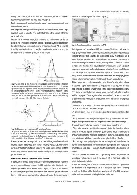
Figure 1. Figure 1. Set-up error measured for <strong>in</strong>dividual patient dur<strong>in</strong>g the fractionated RT treatment<br />
1a. Measured set-up errors for 20 fractions <strong>of</strong> specific patient, <strong>in</strong> two directions (x, y). Each square<br />
represent the set-up error <strong>of</strong> particular fraction. The solid circle <strong>in</strong>dicates the mean <strong>of</strong> these errors <strong>and</strong><br />
the correspond<strong>in</strong>g displacement (arrow `s`) is the systematic set-up error <strong>of</strong> this patient. The total<br />
set-up error <strong>of</strong> any fraction (the greyed square <strong>and</strong> correspond<strong>in</strong>g arrow `t`) is the sum <strong>of</strong> the systematic<br />
error <strong>and</strong> the r<strong>and</strong>om set-up error (arrow `r`) <strong>of</strong> that fraction, b. R<strong>and</strong>om set-up errors (s)<br />
described by st<strong>and</strong>ard deviation (SD) <strong>of</strong> their frequency distribution.<br />
Figure 2. Set-up systematic errors measured for patient specific group<br />
2a. Systematic set-up errors for 10 patients, represented by arrows (an asterisk marks the systematic<br />
error <strong>of</strong> the patient <strong>in</strong> Fig. 1a), b. Frequency distribution <strong>of</strong> systematic set-up errors (solid l<strong>in</strong>e),<br />
measured <strong>in</strong> the patient specific group <strong>of</strong> Fig. 1b.The mean <strong>of</strong> this distribution is <strong>in</strong>dicated by the<br />
vertical l<strong>in</strong>e, which is displaced by some amount from 0, the SD equals S.<br />
However, <strong>geometrical</strong> errors components can be measured <strong>in</strong> a group <strong>of</strong> previously treated<br />
similar patients, <strong>and</strong> described us<strong>in</strong>g st<strong>and</strong>ard deviations (Figure 2 a, b). Once the typical<br />
values for specific group <strong>of</strong> patient are known they can be used to establish <strong>in</strong>stitutional<br />
<strong>correction</strong> protocols <strong>and</strong> <strong>in</strong>cluded <strong>in</strong> the treatment plann<strong>in</strong>g <strong>in</strong> order to def<strong>in</strong>e plann<strong>in</strong>g target<br />
volume (PTV) (2).<br />
ELECTRONIC PORTAL IMAGING DEVICE (EPID)<br />
In recent years, EPIDs have a wide cl<strong>in</strong>ical use for detection <strong>and</strong> management <strong>of</strong> <strong>geometrical</strong><br />
errors dur<strong>in</strong>g radiotherapy treatment. The EPID is attached to the LINAC gantry <strong>and</strong> it<br />
may <strong>in</strong>tercept the exit<strong>in</strong>g photon beams at all gantry angles. EPID uses a fluorescent screen<br />
to convert the high-energy photons <strong>of</strong> the treatment beam <strong>in</strong>to visible light. The light is captured<br />
by a CCD camera or amorphous silicon flat panel detector <strong>and</strong> the ensu<strong>in</strong>g images are<br />
processed <strong>and</strong> analysed by dedicated s<strong>of</strong>tware (Figure 3).<br />
Figure 3. External beam radiotherapy configuration with EPID<br />
The first generation <strong>of</strong> camera-based EPIDs had a number <strong>of</strong> limitations mostly related to<br />
image quality while the current commercially available take advantage <strong>of</strong> flat panel display<br />
technology, provid<strong>in</strong>g faster acquisition <strong>and</strong> superior image quality. In comb<strong>in</strong>ation with a<br />
modern digital accelerator fitted with multileaf collimator, field set-up <strong>and</strong> image acquisition<br />
can be done remotely <strong>and</strong> displayed <strong>in</strong> seconds, obviat<strong>in</strong>g the need to re-enter the treatment<br />
room each time. This allows more frequent treatment verification, or to acquire a series <strong>of</strong><br />
images dur<strong>in</strong>g a s<strong>in</strong>gle treatment for patient movement estimation. Another powerful feature<br />
is that the images are <strong>in</strong> digital form, which allows application <strong>of</strong> s<strong>of</strong>tware tools for process<strong>in</strong>g<br />
to extract <strong>in</strong>formation relevant to treatment verification <strong>and</strong> their manag<strong>in</strong>g by picture<br />
archiv<strong>in</strong>g <strong>and</strong> communication systems (PACS) specially designed for radiotherapy.<br />
EPID is a primary tool for quality assurance <strong>in</strong> radiation delivery. To verify patient position<strong>in</strong>g<br />
the portal image <strong>of</strong> the first treatment is compared with the correspond<strong>in</strong>g reference<br />
image which can be digitised simulator image, but the digitally reconstructed radiography<br />
(DRR), image generated by treatment plann<strong>in</strong>g system from the CT data set is most <strong>of</strong>ten<br />
used for this purpose. Various algorithms have been developed to enable computerized<br />
comparison <strong>of</strong> images for detection <strong>of</strong> field placement errors. This is usually accomplished<br />
<strong>in</strong> several steps:<br />
1. Information about the position <strong>of</strong> the patient anatomy (bony structures) <strong>and</strong> radiation field<br />
is extracted from both portal <strong>and</strong> reference images.<br />
2. A common reference frame for both images is established by registration <strong>of</strong> the radiation<br />
fields.<br />
3. Set-up error is determ<strong>in</strong>ed by register<strong>in</strong>g the patient anatomy <strong>in</strong> both images, then measur<strong>in</strong>g<br />
the result<strong>in</strong>g displacement between the portal <strong>and</strong> reference radiation field edges.<br />
Three most common methods <strong>of</strong> <strong>in</strong>teractive, or manual, image registrations are:<br />
1. The draw<strong>in</strong>g curves technique ("template technique"): by track<strong>in</strong>g the outl<strong>in</strong>es <strong>of</strong> bony<br />
l<strong>and</strong>marks on DRR, same pattern automatically appears on portal image. If the referent <strong>and</strong><br />
portal curves are misaligned <strong>in</strong> relation to the same bony l<strong>and</strong>marks, it <strong>in</strong>dicates the patient<br />
set-up misalignment, which can be corrected accord<strong>in</strong>g to calculation <strong>of</strong> deviation.<br />
2. Po<strong>in</strong>t pair registration: by digitis<strong>in</strong>g the po<strong>in</strong>t over the recognizable bony l<strong>and</strong>mark <strong>in</strong> the<br />
reference image <strong>and</strong> identify<strong>in</strong>g the relations between correspond<strong>in</strong>g po<strong>in</strong>t position <strong>and</strong><br />
bony l<strong>and</strong>mark <strong>in</strong> portal image - if necessary, deviation calculation <strong>and</strong> set up <strong>correction</strong> are<br />
possible.<br />
3. Automatic (s<strong>of</strong>tware) reference <strong>and</strong> portal image match<strong>in</strong>g: reference <strong>and</strong> port image are<br />
automatically overlapped <strong>and</strong> <strong>in</strong> case <strong>of</strong> any apparent shift <strong>in</strong> the images position, the<br />
patient misalignment is <strong>in</strong>dicated.<br />
To def<strong>in</strong>e the position<strong>in</strong>g (<strong>and</strong> set up error) <strong>in</strong> all three planes it is necessary to provide two<br />
sets <strong>of</strong> reference-portal images. Images with 0¼ or 180¼ gantry angle provide position<strong>in</strong>g<br />
<strong>in</strong>formation <strong>in</strong> the lateral <strong>and</strong> longitud<strong>in</strong>al axes, while these with 90¼ or 270¼ gantry angle<br />
provide position<strong>in</strong>g <strong>in</strong>formation <strong>in</strong> the longitud<strong>in</strong>al <strong>and</strong> vertical axes.<br />
www.onk.ns.ac.yu/Archive December 15, 2005<br />
141