Nicrofer® 4221 â alloy 825 - Outokumpu
Nicrofer® 4221 â alloy 825 - Outokumpu
Nicrofer® 4221 â alloy 825 - Outokumpu

You also want an ePaper? Increase the reach of your titles
YUMPU automatically turns print PDFs into web optimized ePapers that Google loves.
Nicrofer ® <strong>4221</strong> – <strong>alloy</strong> <strong>825</strong><br />
Material Data Sheet No. 4001<br />
March 2002 Edition<br />
Corrosion-resistant <strong>alloy</strong><br />
Nicrofer ® <strong>4221</strong><br />
®<br />
<strong>4221</strong><br />
Nicrofer ® <strong>4221</strong><br />
Nicrofer ® <strong>4221</strong><br />
Nicrofer ® 4421<br />
Nicrofer ® <strong>4221</strong><br />
Nicrofe<br />
A company of<br />
ThyssenKrupp<br />
Stainless<br />
ThyssenKrupp VDM<br />
TK
2<br />
Nicrofer ® <strong>4221</strong> – <strong>alloy</strong> <strong>825</strong><br />
Nicrofer <strong>4221</strong> is a titanium-stabilized fully austenitic<br />
nickel-iron-chromium <strong>alloy</strong> with additions of copper and<br />
molybdenum.<br />
Nicrofer <strong>4221</strong> is characterized by:<br />
● good resistance to stress-corrosion cracking<br />
● satisfactory resistance to pitting and crevice corrosion<br />
● good resistance to oxidizing and non-oxidizing hot acids<br />
● good mechanical properties at both room and elevated<br />
temperatures, up to approximately 550 °C (1020 °F)<br />
● approval for pressure vessels with wall temperatures up to<br />
450 °C (842 °F)<br />
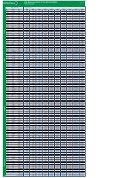
Designation and standards<br />
Country<br />
National<br />
standards<br />
Material<br />
designation<br />
Specification<br />
Chemical Tube and pipe Sheet Rod Strip Wire Forgings<br />
composition and and<br />
seamless welded plate bar<br />
D W.-Nr. 2.4858<br />
NiCr21Mo<br />
DIN 17744 17751 17750 17752 17750 17754<br />
VdTÜV 432 432/2 432/1 432/3 432/1 432/3<br />
F<br />
AFNOR<br />
NC21FeDU<br />
UK<br />
BS NA 16 3074 3072 3076 3073<br />
USA<br />
UNS N08<strong>825</strong><br />
ASTM B 423 B 163 B 424 B 425 B 424<br />
B 704/705<br />
ASME SB 423 SB 163 SB 424 SB 425 SB 424<br />
AMS<br />
ISO<br />
NiFe30Cr21Mo3<br />
Table 1 – Designations and standards.<br />
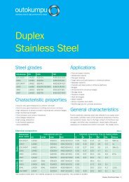
Chemical composition<br />
Ni Cr Fe C Mn Si Cu Mo Al Ti P S<br />
min. 38.0 19.5 1.5 2.5 0.6<br />
bal.<br />
max. 46.0 23.5<br />
0.025 1.0 0.5 3.0 3.5 0.2 1.2 0.020 0.010<br />
Table 2 – Chemical composition (wt.-%) according to VdTÜV 432.<br />
Note: Some compositional limits of other specifications may vary slightly.
3<br />
Physical properties<br />
Density<br />
Melting range<br />
8.1 g/cm 3 0.293 lb/in. 3<br />
1370-1400 °C 2500-2550 °F<br />
Permeability at 20 °C/68 °F (RT)<br />
1.004<br />
Temperature (T) Specific Thermal Electrical Modulus of Coefficient of<br />
heat conductivity resistivity elasticity thermal expansion<br />
between<br />
room temperature<br />
and T<br />
°C °F J Btu W Btu in. µ Ω cm Ω circ mil kN 10 3 ksi 10 -6 10 -6<br />
kg K lb °F m K ft 2 h °F ft mm 2 K °F<br />
0 32 10.5 73 112 677<br />
20 68 440 0.105 10.8 75 112 678 195 28.3<br />
93 200 0.110 85 687 27.4 7.8<br />
100 212 462 12.4 114 190 14.1<br />
200 392 488 14.1 118 185 14.9<br />
204 400 0.117 98 710 26.8 8.3<br />
300 572 514 15.6 120 179 15.2<br />
316 600 0.123 110 728 25.8 8.5<br />
400 762 540 16.9 124 174 15.6<br />
427 800 0.131 120 751 25.0 8.7<br />
500 932 565 18.3 126 168 15.8<br />
538 1000 0.137 131 761 23.8 8.8<br />
600 1112 590 19.6 126 161 16.0<br />
649 1200 0.144 142 762 22.7 9.1<br />
700 1292 615 21.0 127 154 16.7<br />
760 1400 0.153 155 765 21.2 9.5<br />
800 1472 655 23.2 128 142 17.2<br />
871 1600 0.160 172 775 19.4 9.7<br />
900 1652 680 25.7 129 130 17.6<br />
982 1800 0.167 192 782 17.3 9.9<br />
1000 1832 710 28.1 130 119 17.9<br />
Table 3 – Typical physical properties at room and elevated temperatures.
4<br />
Nicrofer ® <strong>4221</strong> – <strong>alloy</strong> <strong>825</strong><br />
Mechanical properties<br />
The following properties are applicable to Nicrofer <strong>4221</strong> in the<br />
soft-annealed (stabilizing annealed) condition and indicated<br />
size ranges.<br />
Specified properties of material outside these size ranges with<br />
agreed properties are subject to special enquiry.<br />
Product Dimensions Yield strength Yield strength Tensile strength Elongation Brinell<br />
R p0.2 R p1.0 R m A 50<br />
hardness<br />
mm inches N/mm 2 ksi N/mm 2 ksi N/mm 2 ksi % HB<br />
Sheet, strip cr 0.5– 6.4 0.018–0.25 ≤ 200<br />
Plate hr 5 –100 3<br />
/16 –4 135–165<br />
240 35 265 38 585 85 30<br />
Rod, bar cf 1.6– 64 1<br />
/16 –2 1 /2<br />
hf 25 –100 1 –4<br />
> 100 –240 > 4 –9 1 /2 220 32 250 36 550 80 35<br />
Tube, pipe hf 64 –240 2 1 /2–9 1 /2 180 25 – – 530 75 30<br />
cf 5 –100 3<br />
/16 –4<br />
Condenser and<br />
heat exch. tube<br />
16 – 76 5<br />
/8 –3<br />
240 35 265 38 585 85 30<br />
Table 4 – Minimum mechanical properties at room temperature according to ASTM.<br />
Product Yield strength , R p0.2 Yield strength, R p1.0<br />
N/mm 2 N/mm 2<br />
Temperature, °C 100 200 300 400 450 100 200 300 400 450<br />
Sheet, strip, plate, tube 205 180 170 160 155 235 205 195 185 180<br />
Rod, bar 190 165 155 145 140 220 190 180 170 165<br />
ksi<br />
ksi<br />
Temperature, °F 200 400 600 800 – 200 400 600 800 –<br />
Sheet, strip, plate, tube 30.5 26.1 26.4 22.6 – 34.8 29.7 28.0 26.3 –<br />
Rod, bar 28.3 23.9 22.2 20.4 – 31.2 27.6 25.8 24.1 –<br />
Table 5 – Minimum short-time mechanical properties in the soft-annealed condition at elevated temperatures according to VdTÜV Material Data Sheet 432.<br />
ISO V-notch impact toughness<br />
Average values at RT: longitudinal ≥ 150 J/cm 2<br />
transverse ≥ 100 J/cm 2
5<br />
Temperature Maximum allowable stress<br />
°C °F N/mm 2 ksi<br />
1) 1) 2) 2)<br />
38 100 21.2 21.2<br />
93 200 21.2 21.2<br />
100 212 146 146<br />
149 300 20.4 21.2<br />
200 392 132 146<br />
204 400 19.2 21.2<br />
260 500 18.3 21.2<br />
300 572 124 146<br />
316 600 17.8 21.2<br />
371 700 17.3 21.0<br />
400 752 119 146<br />
427 800 17.1 20.8<br />
482 900 16.8 20.5<br />
500 932 115 138<br />
538 1000 16.6 19.7<br />
1) metric values determined by interpolation<br />
2) conditional stress values<br />
Table 6 – Maximum allowable stress values in tension according to ASME<br />
UNF-23.3, SB 424.<br />
Conditional stress values<br />
The higher conditional stress values of up to 90% of the yield<br />
strengh at temperature may be used for applications in which<br />
slightly greater deformation is acceptable.These stresses may<br />
result in dimensional changes due to permanent strain and are<br />
not recommended for flanges of gasketed joints.<br />
Metallurgical structure<br />
Nicrofer <strong>4221</strong> has a stable face-centered-cubic structure. The<br />
chemical composition and optimized thermal treatment ensure<br />
that corrosion resistance is not impaired by sensitization.<br />
Corrosion resistance<br />
Nicrofer <strong>4221</strong> is a versatile general engineering <strong>alloy</strong> with resistance<br />
to corrosion in acids and alkalis under both oxidizing and<br />
reducing conditions.<br />
High nickel content gives the <strong>alloy</strong> virtual immunity to stress<br />
corrosion cracking.<br />
Corrosion resistance is good in media as diverse as sulphuric,<br />
sulphurous, phosphoric, nitric and organic acids, alkalis such<br />
as sodium or potassium hydroxide, and acidic chloride<br />
solutions.<br />
The versatility of Nicrofer <strong>4221</strong> is illustrated by its use in nuclear<br />
fuel element dissolvers where a variety of corrosive media, e. g.<br />
sulphuric and nitric acids and sodium hydroxide, are handled in<br />
the same equipment.<br />
Applications<br />
Nicrofer <strong>4221</strong> is used in a wide variety of applications up to a<br />
temperature of approximately 550 °C (1020 °F).<br />
1000<br />
1800<br />
Typical examples are:<br />
● components such as heating coils, tanks, crates, baskets<br />
and chains in sulphuric acid pickling plants<br />
Temperature, °C<br />
900<br />
800<br />
700<br />
600<br />
500<br />
IC > 50 µm<br />
(0.002 in.)<br />
1600<br />
1400<br />
1200<br />
1000<br />
Temperature, °F<br />
● fuel element dissolvers<br />
● sea-water-cooled heat exchangers, offshore product piping<br />
systems; tubes and components in sour gas service<br />
● heat exchangers, evaporators, scrubbers, dip pipes etc. in<br />
phosphoric acid production<br />
● air-cooled heat exchangers in petroleum refineries<br />
● food processing<br />
● chemical plant<br />
● combustion-resistant <strong>alloy</strong> for high pressure O 2 applications<br />
400<br />
1 10 100<br />
Sensitization time, h<br />
800<br />
Fabrication and heat treatment<br />
Nicrofer <strong>4221</strong> can readily be hot- and cold-worked and<br />
machined.<br />
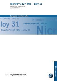
Fig. 1 – Time-temperature-sensitization (TTS) diagram for Nicrofer <strong>4221</strong><br />
sheet (C=0.010%) after Streicher test, according to ASTM G-28, method A.
6<br />
Nicrofer ® <strong>4221</strong> – <strong>alloy</strong> <strong>825</strong><br />
Heating<br />
Temperature control is important to ensure that the corrosion<br />
resistance of the <strong>alloy</strong> is not impaired by sensitization.<br />
Workpieces must be clean and free from all kinds of contaminants<br />
before and during any heat treatment.<br />
Nicrofer <strong>4221</strong> may become embrittled if heated in the presence<br />
of contaminants such as sulphur, phosphorus, lead and<br />
other low-melting-point metals. Sources of such contaminants<br />
include marking and temperature-indicating paints and<br />
crayons, lubricating grease and fluids, and fuels.<br />
Fuels must be as low in sulphur as possible. Natural gas<br />
should contain less than 0.1 wt.-% sulphur. Fuel oils containing<br />
no more than 0.5 wt.-% sulphur are suitable.<br />
Due to their close control of temperature and freedom from<br />
contamination, thermal treatments in electric furnaces under<br />
vacuum or an inert gas atmosphere are to be preferred.<br />
Treatments in an air atmosphere and alternatively in gas-fired<br />
furnaces are acceptable though, if contaminants are at low<br />
levels so that a neutral or slightly oxidizing furnace atmosphere<br />
is attained. A furnace atmosphere fluctuating between<br />
oxidizing and reducing must be avoided as well as direct<br />
flame impingement on the metal.<br />
Hot working<br />
Nicrofer <strong>4221</strong> may be hot-worked in the temperature range<br />
1150 to 900 °C (2100 to 1650 °F). Cooling after hot working<br />
should be by water quenching or rapid air cooling.<br />
For hot working the material may be charged into the furnace<br />
at working temperature. When the furnace has returned to<br />
temperature the work piece should be soaked for 60 minutes<br />
per 100 mm (4 in.) of thickness. At the end of this period it<br />
should be withdrawn immediately and worked within the<br />
above temperature range. If the metal temperature falls below<br />
the minimum hot working temperature, it must be reheated.<br />
Annealing is required after hot working to ensure maximum<br />
corrosion resistance and optimum grain micro-structure.<br />
Cold working<br />
Cold working should be carried out on annealed material.<br />
Nicrofer <strong>4221</strong> has a work-hardening rate similar to that of<br />
austenitic stainless steels. This should be taken into account<br />
when selecting the forming equipment.<br />
Interstage annealing may become necessary with high<br />
degrees of cold forming.<br />
After final cold-working with more than 15% deformation a<br />
stabilizing anneal is required.<br />
Due to the possibility of galling, carbon steel is not recommended<br />
for dies, which should be of <strong>alloy</strong> tool steel, tungsten<br />
carbide or cast iron.<br />
Heat treatment<br />
Soft or stabilizing anneals should be carried out in the temperature<br />
range 920 to 980 °C (1690 to 1800 °F) preferably at<br />
940 ± 10 °C (1725 ± 15 °F). Water quenching or rapid air<br />
cooling is recommended for thicknesses above about 1.5 mm<br />
(0.06 in.), and is essential for maximum corrosion resistance.<br />
For any thermal treatment the material should be charged<br />
into the furnace at temperature observing the precautions<br />
concerning cleanliness mentioned earlier under ‘Heating’.<br />
Descaling and pickling<br />
Oxides of Nicrofer <strong>4221</strong> and discoloration adjacent to welds,<br />
are more adherent than on stainless steels. Grinding with very<br />
fine abrasive belts or discs is recommended. Care should be<br />
taken to prevent tarnishing.<br />
Before pickling in a nitric/hydrofluoric acid mixture, the surface<br />
oxide layer must be broken up by abrasive blasting or<br />
grinding or by pretreatment in a fused salt bath. Particular<br />
attention should be paid to the pickling time.<br />
Machining<br />
Nicrofer <strong>4221</strong> should be machined in the annealed condition.<br />
As the <strong>alloy</strong> is prone to work-hardening low cutting speeds<br />
should be used and the tool should be engaged at all times.<br />
Heavy feeds are important in getting below the workhardened<br />
surface layer.<br />
Welding<br />
When welding nickel-base <strong>alloy</strong>s, the following instructions<br />
should be adhered to:<br />
Workplace<br />
The workplace should be in a separate location, well away<br />
from areas where carbon steel fabrication takes place. Maximum<br />
cleanliness and avoidance of draughts are paramount.<br />
Auxiliaries, clothing<br />
Clean fine leather gloves and clean working clothes should be<br />
used.<br />
Tools and machines<br />
Tools used for nickel-base <strong>alloy</strong>s and stainless steels must<br />
not be used for other materials. Brushes should be made of<br />
stainless materials.<br />
Fabricating and working machinery such as shears, presses<br />
or rollers should be fitted with means (felt, cardboard, plastic<br />
sheeting) of avoiding contamination of the metal with ferrous<br />
particles, which can be pressed into the surface and thus lead<br />
to corrosion.<br />
Cleaning<br />
Cleaning of the base metal in the weld area (both sides) and<br />
of the filler metal (e.g. welding rod) should be carried out with<br />
ACETONE.<br />
Trichlorethylene (TRI), perchlorethylene (PER) and carbon<br />
tetrachloride (TETRA) must not be used.<br />
Edge preparation<br />
This should preferably be done by mechanical means by<br />
turning, milling or planing; plasma cutting is also possible.
7<br />
However, in the latter case the cut edge (the face to be<br />
welded) must be finished of cleanly. Careful grinding without<br />
overheating is permitted. Also a zone approximately 25 mm<br />
(1 in.) wide on each side of the joint should be ground to<br />
bright metal.<br />
Included angle<br />
The different physical characteristics of nickel-base <strong>alloy</strong>s and<br />
special stainless steels compared with carbon steel generally<br />
manifest themselves in a lower thermal conductivity and a<br />
higher rate of thermal expansion.<br />
This should be allowed for by means of, among other things,<br />
wider root gaps or openings (1-3 mm), while larger included<br />
angles (60-70°), as shown in Fig. 2, should be used for individual<br />
butt joints owing to the viscous nature of the molten<br />
weld metal and to counteract the pronounced shrinkage<br />
tendency.<br />
Striking of the arc<br />
The arc should only be struck in the weld area, e.g. on the<br />
faces to be welded or on a run-out piece. Striking marks lead<br />
to corrosion.<br />
Welding processes<br />
Nicrofer <strong>4221</strong> can be joined to itself and to many other<br />
metals by conventional welding processes. These include<br />
GTAW (TIG), plasma arc, GMAW (MIG/MAG) and SMAW<br />
(MMA). Pulsed arc welding is the preferred technique. For the<br />
MAG process the use of a multi-component shielding gas<br />
(Ar + He + H2 + CO2) is recommended.<br />
For welding, Nicrofer <strong>4221</strong> should be in the annealed condition<br />
and be free from scale, grease and markings. When<br />
welding the root, care should be taken to achieve best-quality<br />
root backing (argon 99.99), so that the weld is free from<br />
oxides after welding the root. Any heat tint should be removed<br />
preferably by brushing with a stainless steel wire brush<br />
while the weld metal is still hot.<br />
Filler metal<br />
For the gas-shielded welding processes, the following filler<br />
metals are recommended:<br />
Bare electrodes: Nicrofer S 6020 – FM 625<br />
Werkstoff-Nr. 2.4831<br />
SG-NiCr 21 Mo 9 Nb<br />
AWS A 5.14: ERNiCrMo-3<br />
Covered electrodes: Werkstoff-Nr. 2.4621<br />
EL-NiCr 20 Mo 9 Nb<br />
AWS A 5.11: ENiCrMo-3<br />
Welding parameters and influences<br />
(heat input/linear energy input per unit length of weld)<br />
Care should be taken that the work is performed with a deliberately<br />
chosen, low heat input as indicated in Table 8 by way<br />
of example. Use of the stringer bead technique should be<br />
aimed at. Interpass temperature should be kept below 120 °C<br />
(250 °F).<br />
The welding parameters should be monitored as a matter of<br />
principle.<br />
The heat input Q may be calculated as follows:<br />
Q = U x I x 60 (kJ/cm)<br />
v x 1000<br />
U = arc voltage, volts<br />
I = welding current, amps<br />
v = welding speed, cm/min.<br />
Consultation with ThyssenKrupp VDM’s Welding Laboratory is<br />
recommended.<br />
approx.2 mm<br />
approx.2 mm<br />
approx.2 mm<br />
Straight butt weld<br />
Sheet thickness up to 2.5 mm<br />
approx.2 mm<br />
Single-V weld<br />
60 - 70°<br />
Single-U weld<br />
R=6<br />
Double-V weld<br />
60 - 70°<br />
Sheet/plate<br />
thickness 2.5-15 mm<br />
Plate<br />
thickness 12-25 mm<br />
Plate<br />
thickness 16-25 mm<br />
0-2mm<br />
approx. 1.5 mm<br />
up to 2 mm<br />
Fig. 2 – Edge preparation for welding of nickel-base <strong>alloy</strong>s and special<br />
stainless steels.<br />
15°<br />
Double-U weld<br />
15°<br />
R=6<br />
Plate thickness<br />
over 25 mm<br />
2mm
8<br />
Nicrofer ® <strong>4221</strong> – <strong>alloy</strong> <strong>825</strong><br />
Sheet/ Welding Filler metal Welding parameters Welding Flux/ Plasma- Plasma/<br />
plate process Diameter Speed Root pass Intermediate and speed shielding gas rate nozzle<br />
thick- final passes gas diameter<br />
ness<br />
rate<br />
mm mm m/min. A V A V cm/min. l/min. l/min. mm<br />
3.0 Manual 2.0 90 10 110-120 11 10–15 Ar W3 1)<br />
GTAW 8–10<br />
6.0 Manual 2.0–2.4 100–110 10 120-130 12 10–15 Ar W3 1)<br />
GTAW 8–10<br />
8.0 Manual 2.4 110–120 11 130-140 12 10–15 Ar W3 1)<br />
GTAW 8–10<br />
10.0 Manual 2.4 110–120 11 130-140 12 10–15 Ar W3 1)<br />
GTAW 8–10<br />
3.0 Autom. 1.2 0.5 manual 150 10 25 Ar W3 1)<br />
GTAW 15-20<br />
5.0 Autom. 1.2 0.5 manual 150 10 25 Ar W3 1)<br />
GTAW 15-20<br />
2.0 Hot wire 1.0 0.3 180 10 80 Ar W3 1)<br />
GTAW 15-20<br />
10.0 Hot wire 1.2 0.45 manual 250 12 40 Ar W3 1)<br />
GTAW 15-20<br />
4.0 Plasma 1.2 0.5 165 25 25 Ar W3 1) Ar W3 1) 3.2<br />
arc 30 3.0<br />
6.0 Plasma 1.2 0.5 190–200 25 25 Ar W3 1) Ar W3 1) 3.2<br />
arc 30 3.5<br />
8.0 MIG/MAG 1.0 approx. GTAW 130-140 23-27 24-30<br />
GMAW 8<br />
10.0 MIG/MAG 1.2 approx. GTAW 130-150 23-27 20–26<br />
GMAW 5<br />
6.0 SMAW 2.5 40–70 approx. 40–70 approx.<br />
21 21<br />
8.0 SMAW 2.5–3.25 40–70 approx. 70–100 approx.<br />
21 22<br />
16.0 SMAW 4.0 90–130 approx.<br />
22<br />
1) Argon or argon + max. 3 % hydrogen.<br />
2) For MAG welding the use of the shielding gas Cronigon He30S or Argomag–Ni, for example, is recommended.<br />
In all gas-shielded welding operations, ensure adequate back shielding.<br />
These figures are only a guide and are intended to facilitate setting of the welding machines.<br />
Table 7 – Welding parameters (guide values)<br />
MAG 2)<br />
MIG: argon<br />
18–20<br />
MAG 2)<br />
MIG: argon<br />
18–20<br />
Welding process Heat input per unit length Welding process Heat input per unit length<br />
kJ/cm<br />
kJ/cm<br />
GTAW, manual, fully mechanised max. 10 GMAW, MIG/MAG, manual, fully mechanised max. 11<br />
Hot wire GTAW max. 6 SMAW, manual metal arc (MMA) max. 7<br />
Plasma arc max. 10<br />
Table 8 – Heat input per unit length (guide values)
9<br />
Postweld treatment<br />
(brushing, pickling and thermal treatments)<br />
Brushing with a stainless steel wire brush immediately after<br />
welding, i.e. while the metal is still not generally results in<br />
removal of heat tint and produces the desired surface condition<br />
without additional pickling.<br />
Pickling, if required or prescribed, however, would generally<br />
be the last operation performed on the weldment. Also refer<br />
to the information on ‘Descaling and pickling’.<br />
Neither pre- nor postweld thermal treatments are required.<br />
Availability<br />
Nicrofer <strong>4221</strong> is available in the following standard product<br />
forms:<br />
Sheet & plate<br />
(for cut-to-length availability, refer to strip)<br />
Conditions:<br />
hot or cold rolled (hr, cr)<br />
thermally treated and pickled<br />
Thickness hr / cr Width 1) Length 1)<br />
mm mm mm<br />
1.10 – < 1.50 cr 2000 8000<br />
1.50 – < 3.00 cr 2500 8000<br />
3.00 – < 7.50 cr / hr 2500 8000<br />
7.50 – ≤ 25.00 hr 2500 8000 2)<br />
> 25.00 1) hr 2500 2) 8000 2)<br />
Discs and rings<br />
Conditions:<br />
hot rolled or forged,<br />
thermally treated,<br />
pickled or machined<br />
Product Weight Thickness O.D. 1) I.D. 1)<br />
kg mm mm mm<br />
Disc ≤10000 ≤300 ≤3000<br />
Ring ≤ 3000 ≤200 ≤ 2500 on request<br />
Ibs inches inches inches<br />
Disc ≤22000 ≤12 ≤120<br />
Ring ≤ 6600 ≤ 8 ≤100 on request<br />
1) other sizes subject to special enquiry<br />
Rod & bar<br />
Conditions:<br />
forged, rolled, drawn,<br />
thermally treated,<br />
pickled, machined, peeled or ground<br />
Product Forged 1) Rolled 1) Drawn 1)<br />
mm mm mm<br />
Rod (o.d.) ≤600 8–100 12–65<br />
Bar, square (a) 40–600 15–280 not standard<br />
Bar, flat (a x b) (40–80) (5–20) (10–20)<br />
x x x<br />
(200–600) (120–600) (30–80)<br />
Bar, hexagonal (s) 40–80 13–41 ≤50<br />
inches inches inches<br />
0.043 – < 0.060 cr 80 320<br />
0.060 – < 0.120 cr 100 320<br />
0.120 – < 0.300 cr / hr 100 320<br />
0.300 – ≤ 1.000 hr 100 320 2)<br />
> 1.000 1) hr 100 2) 320 2)<br />
1) other sizes subject to special enquiry<br />
2) depending on piece weight<br />
inches inches inches<br />
Rod (o.d.) ≤24 5<br />
/16–4 1<br />
/2–2 1 /2<br />
Bar, square (a) 1 5 /8–24<br />
10<br />
/16–11 not standard<br />
Bar, flat (a x b) (1 5 /8–3 1 /8) ( 3 /16– 3 /4) ( 3 /8– 3 /4)<br />
x x x<br />
(8–24) (4 3 /4–24) (1 1 /4–3 1 /8)<br />
Bar, hexagonal (s) 1 5 /8–3 1 /8<br />
1<br />
/2–1 5 /8 ≤2<br />
1) other sizes and conditions subject to special enquiry
10<br />
Forgings<br />
Shapes other than discs, rings, rod and bar are subject to<br />
special enquiry. Flanges and hollow shafts may be available<br />
up to a piece weight of 10 t.<br />
Strip 1)<br />
Conditions:<br />
cold rolled,<br />
thermally treated and pickled or bright annealed 2)<br />
Thickness Width 3) Coil I.D.<br />
mm mm mm<br />
0.04–≤0.10 4–200 300 400<br />
> 0.10–≤0.20 4–350 300 400 500<br />
> 0.20–≤0.25 4–750 400 500 600<br />
> 0.25–≤0.60 6–750 400 500 600<br />
> 0.60–≤1.0 8–750 400 500 600<br />
> 1.0 –≤2.0 15–750 400 500 600<br />
> 2.0 –≤3.0 25–750 400 500 600<br />
The information contained in this data sheet is based on results of research<br />
and development work available at the time of printing and does not provide<br />
any guarantee of particular characteristics or fit. ThyssenKrupp VDM reserves<br />
the right to make changes without notice. The data sheet has been compiled<br />
to the best knowledge of ThyssenKrupp VDM and is given without any liability<br />
on the part of ThyssenKrupp VDM.<br />
ThyssenKrupp VDM is only liable according to the terms of the sales contract<br />
and in particular to the General Conditions of Sales in case of delivery from<br />
ThyssenKrupp VDM.<br />
As updates of data sheets are not automatically send out, when issued,<br />
ThyssenKrupp VDM recommends to request the latest edition of required data<br />
sheets either by phone +49(0)2392 55 2493, by fax +49(0)2392 55 2111 or<br />
by E-mail under info@vdm.thyssenkrupp.com.<br />
March 2002 Edition.<br />
This edition supersedes data sheet no. 4001, dated December 1993.<br />
inches inches inches<br />
0.0016–≤0.004 0.16– 8 12 16<br />
> 0.004 –≤0.008 0.16–14 12 16 20<br />
> 0.008 –≤0.010 0.16–30 16 20 24<br />
> 0.010 –≤0.024 0.20–30 16 20 24<br />
> 0.024 –≤0.040 0.32–30 16 20 24<br />
> 0.040 –≤0.080 0.60–30 16 20 24<br />
> 0.080 –≤0.120 1.0 –30 16 20 24<br />
1) Cut-to-length available in lengths from 250 to 4000 mm (10 to 158 in.)<br />
2) Maximum thickness 3 mm (0.125 in.)<br />
3) Wider widths subject to special enquiry<br />
Wire<br />
Conditions:<br />
bright drawn, 1 /4 hard to hard,<br />
bright annealed<br />
Dimensions:<br />
0.01–12.0 mm (0.0004–0.47 in.) diameter,<br />
in coils, pay-off packs, on spools and spiders<br />
Welding filler metals<br />
Suitable welding rods, wire, strip electrodes and electrode<br />
core wire are available in all standard sizes.<br />
Seamless tube and pipe<br />
Using ThyssenKrupp VDM cast materials seamless tubes and<br />
pipes are produced and available from DMV STAINLESS Int.<br />
Sales, Tour Neptune, F-92086 Paris, La Defence Cedex<br />
(Fax: +33-1-4796 8126; Tel.: +33-1-4796 8128).<br />
Welded tube and pipe<br />
Welded tubes and pipes are obtainable from qualified manufacturers<br />
using ThyssenKrupp VDM semi-fabricated products.
ThyssenKrupp VDM GmbH<br />
Plettenberger Strasse 2<br />
58791 Werdohl<br />
P. O. Box 18 20<br />
58778 Werdohl<br />
Germany<br />
Phone: +49 (23 92) 55-0<br />
Fax: +49 (23 92) 55-22 17<br />
E-Mail: info@vdm.thyssenkrupp.com<br />
Internet http://www.thyssenkruppvdm.de<br />
rofer