APPENDIX L POWER SUPPLIES 2. WP-775B Single-Output DC ...
APPENDIX L POWER SUPPLIES 2. WP-775B Single-Output DC ...
APPENDIX L POWER SUPPLIES 2. WP-775B Single-Output DC ...

Create successful ePaper yourself
Turn your PDF publications into a flip-book with our unique Google optimized e-Paper software.
<strong>APPENDIX</strong> L <strong>POWER</strong> <strong>SUPPLIES</strong><br />
<strong>2.</strong> <strong>WP</strong>-<strong>775B</strong> <strong>Single</strong>-<strong>Output</strong> <strong>DC</strong> Power Supply<br />
Purpose:<br />
The <strong>WP</strong>-<strong>775B</strong> <strong>Single</strong>-<strong>Output</strong> <strong>DC</strong> Power Supply, hereafter denoted “power supply”<br />
provides both adjustable output voltage and direct current.<br />
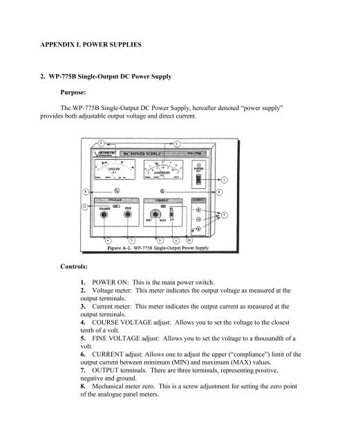
Controls:<br />
1. <strong>POWER</strong> ON: This is the main power switch.<br />
<strong>2.</strong> Voltage meter: This meter indicates the output voltage as measured at the<br />
output terminals.<br />
3. Current meter: This meter indicates the output current as measured at the<br />
output terminals.<br />
4. COURSE VOLTAGE adjust: Allows you to set the voltage to the closest<br />
tenth of a volt.<br />
5. FINE VOLTAGE adjust: Allows you to set the voltage to a thousandth of a<br />
volt.<br />
6. CURRENT adjust: Allows one to adjust the upper (“compliance”) limit of the<br />
output current between minimum (MIN) and maximum (MAX) values.<br />
7. OUTPUT terminals. There are three terminals, representing positive,<br />
negative and ground.<br />
8. Mechanical meter zero. This is a screw adjustment for setting the zero point<br />
of the analogue panel meters.
9. HI/LO switch. This switch selects the top (HI) or bottom (LO) scale of the<br />
current output and corresponding meter scale. You should not adjust this without<br />
consulting your instructor, since HI range currents may damage equipment.<br />
10. CC lamp: When the power supply is in an overload or short condition, the<br />
light will be ON. It means that the output <strong>DC</strong> voltage will be down until output<br />
current adjust is cut to a lower value.<br />
11. CV lamp: When the power supply is in a normal working mode, the lamp<br />
will be ON. But when the power supply is in an overload or short condition, the<br />
light will be OFF.<br />
Preset Procedures:<br />
1. Before applying power, make sure that the AC input voltage is correctly set on<br />
the back of the power supply for your available power.<br />
<strong>2.</strong> Connect the power supply to an AC power source using the line cord provided<br />
and turn the <strong>POWER</strong> ON switch on. For maximum stability, allow the<br />
instrument to warm up for at least 20 minutes.<br />
3. Set the voltage and current adjustment knobs as you desire.<br />
Operating Notes:<br />
1. Verify that the AC voltage setting is the same as your available power before<br />
you apply power to the power supply.<br />
<strong>2.</strong> Do not connect a voltage that is greater than the current output voltage to the<br />
terminals of the instrument.<br />
3. Do not connect the output of two or more power supplies in parallel.<br />
4. When the power supply is not to be used in a portion of the procedure, turn the<br />
output voltage to minimum.<br />
3. Tektronix PS281 <strong>DC</strong> Power Supply<br />
Purpose:<br />
The PS281 <strong>DC</strong> Power Supply, hereafter denoted “power supply” provides both adjustable<br />
output voltage and direct current at up to 90 W of power (up to 30 V, 3 A), with a 3 and one-half<br />
digit digital readout.<br />
Front Panel Controls:<br />
1. <strong>POWER</strong> switch: Turns on the AC line power to the instrument.<br />
<strong>2.</strong> Digital readout: A four-digit display that shows the output of the power supply<br />
in either volts or amperes.<br />
3. VOLTS/AMPS selector: A switch that controls which unit (amps or volts) is<br />
displayed on the readout; an LED will light next to the unit presently displayed.<br />
This switch only affects the display; it does not affect the output of the supply in
any way.<br />
4. VOLTAGE controls: The FINE and COURSE voltage knobs can be turned to<br />
set the output voltage when in the constant voltage mode. The constant voltage<br />
(C.V.) indicator lights when the power supply is in the constant voltage mode<br />
(when the voltage limit is set lower than the current limit for a given load).<br />
5. CURRENT controls: The FINE and COURSE current knobs can be turned to<br />
set the output current when in the constant current mode. The constant current<br />
(C.C.) indicator lights when the power supply is in the constant current mode<br />
(when the current limit is set lower than the voltage limit for a given load). The<br />
HI/LO AMPS button selects either a high or low (greater or less than 2A,<br />
respectively) range of current.<br />
6. <strong>Output</strong> jacks: Banana jacks that carry the power supply output to a load. The<br />
plus (red) and minus (black) carry current, and the ground (green) jack is<br />
connected to the chasis and earth ground through the AC power cord.<br />
Rear Panel Controls:<br />
1. Power cord jack: A standard, three-prong power connector to receive AC line<br />
power.<br />
<strong>2.</strong> Safety fuse holder: A safety fuse is located beneath the power cord jack to<br />
protect the instrument against drawing excessive current. A spare fuse is also<br />
located in the holder.<br />
3. LINE VOLTAGE SELECT: Consists of a top switch and bottom switch that<br />
are set in tandem to configure the power supply for the available AC power (100,<br />
120, 220 or 240 V). See the label on the back of the power supply for the<br />
appropriate switch positions for each AC voltage type. Consult your instructor if<br />
you are unsure of the proper setting of these switches.<br />
4. REMOTE section: The switches and terminals in this section are used to set<br />
the power supply up in a parallel or series connection with other supplies, use the<br />
supply in the MASTER or SLAVE modes, or control the power supply output via<br />
an externally applied (remote) voltage source. These controls will not be used in<br />
laboratory exercises. Consult your instructor or the power supply manual if<br />
questions arise concerning these controls.<br />
Preset Procedures:<br />
1. Before applying power, make sure that the AC input voltage is correctly set on<br />
the back of the power supply for your available power.<br />
<strong>2.</strong> Connect the power supply to an AC power source using the line cord provided<br />
and turn the <strong>POWER</strong> ON switch on. For maximum stability, allow the<br />
instrument to warm up for at least 20 minutes.<br />
3. Initially set the voltage and current adjustment knobs to full counterclockwise<br />
(effectively no output) position; then you may adjust them as you desire.<br />
Operating Notes:
1. Verify that the AC voltage setting is the same as your available power before<br />
you apply power to the power supply.<br />
<strong>2.</strong> Do not connect a voltage that is greater than the current output voltage to the<br />
terminals of the instrument.<br />
3. Do not connect the output of two or more power supplies in parallel.<br />
4. When the power supply is not to be used in a portion of the procedure, turn the<br />
output voltage to minimum.<br />
5. A more precise multimeter may be necessary to accurately read output levels at<br />
low output settings, due to the limited precision of the 3.5 digit display (e.g., only<br />
one digit may be active).