FRS-2021 DAEWOO ELECTRONICS CORP.
FRS-2021 DAEWOO ELECTRONICS CORP.
FRS-2021 DAEWOO ELECTRONICS CORP.

You also want an ePaper? Increase the reach of your titles
YUMPU automatically turns print PDFs into web optimized ePapers that Google loves.
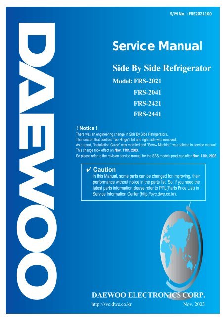
Service Manual<br />
Side By Side Refrigerator<br />
Model: <strong>FRS</strong>-<strong>2021</strong><br />
<strong>FRS</strong>-2041<br />
<strong>FRS</strong>-2421<br />
<strong>FRS</strong>-2441<br />
S/M No. : <strong>FRS</strong><strong>2021</strong>100<br />
! Notice !<br />
There was an engineering change in Side By Side Refrigerators.<br />
The function that controls Top Hinge's left and right side was removed.<br />
As a result, "Installation Guide" was modified and "Screw Machine" was deleted in service manual.<br />
This change took effect on Nov. 11th, 2003.<br />
So please refer to the revision service manual for the SBS models produced after Nov. 11th, 2003.<br />
✔ Caution<br />
: In this Manual, some parts can be changed for improving, their<br />
performance without notice in the parts list. So, if you need the<br />
latest parts information,please refer to PPL(Parts Price List) in<br />
Service Information Center (http://svc.dwe.co.kr).<br />
<strong>DAEWOO</strong> <strong>ELECTRONICS</strong> <strong>CORP</strong>.<br />
http://svc.dwe.co.kr Nov. 2003
TABLE OF CONTENTS<br />
1. EXTERNAL VIEWS ---------------------------------------- 3<br />
1-1. EXTERNAL SIZE ---------------------------------------- 3<br />
1-2. NAME OF PARTS ---------------------------------------- 7<br />
2. SPECIFICATIONS ---------------------------------------- 9<br />
2-1. OUTLINE ---------------------------------------- 9<br />
2-2. ELECTRIC PARTS ---------------------------------------- 10<br />
2-3. POWER CORD ---------------------------------------- 13<br />
2-4. DOOR COLOR ---------------------------------------- 14<br />
3. OPERATIONS AND FUNCTIONS ---------------------------------------- 15<br />
---------------------------------------- 41<br />
4. DIAGRAM<br />
4-1. WIRING DIRGRAM ---------------------------------------- 41<br />
4-2. CIRCUIT DIAGRAM ---------------------------------------- 42<br />
4-3. AIR FIOW DIAGRAM ---------------------------------------- 44<br />
4-4. REFRIGERANT CYCLE DIAGRAM ---------------------------------------- 45<br />
5. DISASSEMBLY AND ASSEMBLY ---------------------------------------- 46<br />
6. INSTALLATION GUIDE ---------------------------------------- 54<br />
7. EXPLODED VIEW AND PART LIST---------------------------------------- 60<br />
7-1. TOTAL EXPLODED VIEW ---------------------------------------- 60<br />
7-2. TOTAL PART LIST ---------------------------------------- 68<br />
SAFETY AND PRECAUTIONS<br />
1) For starters, be sure to check any chances of the leakage of electricity<br />
2) You could handle a part in the vicinity of electricity after unplugging<br />
3) You should put on rubber glovers to prevent an electric shock on operation test<br />
4) Make sure the rated current, voltage, capacity before using an instrument<br />
5) Keep your wet hands away from the metal goods in the freezer compartment not to be frostbitten<br />
6) Be careful not to let water to permeate the electric part in the machine room<br />
7) with the door open during your working, you might be damaged by that door<br />
8) You should give a tilt to the refrigerator for your safe after removing the breakable<br />
goods inside the refrigerator<br />
9) You'd better use cotton gloves if you fix it up around the evaporator
1. EXTERNAL VIEWS<br />
1-1. EXTERNAL SIZE<br />
391<br />
1808<br />
1650<br />
<strong>FRS</strong>-<strong>2021</strong><br />
108<br />
82.5<br />
925<br />
25.5<br />
651<br />
524<br />
- 3 -<br />
20<br />
127<br />
61 66<br />
12.5<br />
30<br />
816<br />
676.5<br />
50<br />
1707<br />
3.5<br />
47.5
391<br />
1808<br />
1650<br />
<strong>FRS</strong>-2041<br />
108<br />
82.5<br />
925<br />
25.5<br />
651<br />
524<br />
- 4 -<br />
20<br />
127<br />
61 66<br />
12.5<br />
30<br />
816<br />
676.5<br />
50<br />
1707<br />
3.5<br />
47.5
391<br />
1808<br />
1650<br />
<strong>FRS</strong>-2421<br />
108<br />
82.5<br />
925<br />
25.5<br />
731<br />
524<br />
- 5 -<br />
20<br />
127<br />
61 66<br />
12.5<br />
30<br />
896<br />
756.5<br />
50<br />
1707<br />
3.5<br />
47.5
391<br />
1808<br />
1650<br />
<strong>FRS</strong>-2441<br />
108<br />
82.5<br />
925<br />
25.5<br />
731<br />
524<br />
- 6 -<br />
20<br />
127<br />
61 66<br />
12.5<br />
30<br />
896<br />
756.5<br />
50<br />
1707<br />
3.5<br />
47.5
1-2. NAME OF PARTS<br />
1<br />
2<br />
3<br />
5<br />
6<br />
7<br />
8<br />
<strong>FRS</strong>-<strong>2021</strong> / <strong>FRS</strong>-2421<br />
Freezer Compartment Refrigerator Compartment<br />
1. Freezer Light 9. Deodorizer<br />
2. Freezer Pockets 10. Dairy Pocket<br />
3. Freezer Shelves 11. Refrigerator Top Light<br />
5. Ice Cubes Maker 12. Refrigerator Small Pocket<br />
6. Ice Cubes Case 13. Foldaway Wine Support<br />
7. Freezer Case 14. Chilled Case<br />
8. Front Cover 15. Refrigerator Bottom Light<br />
16. Refrigerator Shelves<br />
17. Egg Case<br />
18. Refrigerator Pockets<br />
19. Vegetables Case<br />
20. Fruits Case<br />
- 7 -<br />
9<br />
10<br />
11<br />
12<br />
13<br />
14<br />
15<br />
16<br />
17<br />
18<br />
19<br />
20
1<br />
2<br />
3<br />
5<br />
6<br />
7<br />
8<br />
<strong>FRS</strong>-2041 / <strong>FRS</strong>-2441<br />
Freezer Compartment Refrigerator Compartment<br />
1. Freezer Light 9. Deodorizer<br />
2. Freezer Pockets 10. Diary Pocket<br />
3. Freezer Shelves 11. Refrigerator Top Light<br />
5. Ice Cubes Maker 12. Refrigerator Small Pocket<br />
6. Ice Cubes Case 13. Foldaway Wine Support<br />
7. Freezer Cases 14. Chilled Case<br />
8. Front Cover 15. Refreshment (Home-Bar) Pocket<br />
- 8 -<br />
16. Refrigerator Bottom Light<br />
17. Refrigerator Shelves<br />
18. Egg Case<br />
19. Refrigerator Pockets<br />
20. Vegetables Case<br />
21. Fruits Case<br />
9<br />
10<br />
11<br />
12<br />
13<br />
14<br />
15<br />
16<br />
17<br />
18<br />
19<br />
20<br />
21
2. SPECIFICATIONS<br />
2-1. OUTLINE<br />
MODEL NAME<br />
USABLE CAPACITY (L)<br />
EXTERNAL<br />
DIMENSION (mm)<br />
FREEZER<br />
REFRIGERATOR<br />
TOTAL<br />
WIDTH<br />
DEPTH<br />
HEIGHT<br />
REFRIGENT R134a<br />
COOLING & CONTROL<br />
SYSTEM<br />
NET WEIGHT (kg)<br />
DIVISION<br />
COOLING SYSTEM<br />
DEFROST SYSTEM<br />
DEFORST CONTROL<br />
- 9 -<br />
<strong>FRS</strong>-<strong>2021</strong> <strong>FRS</strong>-2041 <strong>FRS</strong>-2421 <strong>FRS</strong>-2441<br />
215<br />
370<br />
585<br />
925<br />
816<br />
1808<br />
CONTENTS<br />
150/190<br />
Fan Cooling System<br />
Fin Evaporator Forced<br />
Automatic Start & Stop<br />
256<br />
430<br />
686<br />
925<br />
896<br />
1808<br />
112 114 120 122
2-2 ELECTRIC PARTS<br />
1) COMPRESSOR<br />
REFRIGERANT R134a<br />
VOLTAGE ( V/HZ) 100 /50,60 110 / 60 115,120/60 127/60 220 / 60 220 ~240/50<br />
230 /50<br />
(EUROP)<br />
COMP MODEL X HBL27YG-3 X HCL27YG-2 HPL27YG-4A HPL30YG-5 DK190Q-L2U<br />
PART CODE<br />
X 3952127R30 X 3957127R20 3956127R40 395S130R50 3956190D50<br />
STARTING TYPE X CSR X CSIR RSCR RSCR RSCR<br />
2) RELAY<br />
REFRIGERANT R134a<br />
VOLTAGE ( V/HZ) 100 /50,60 110 / 60 115,120/60 127/60 220 / 60 220~240 / 50 230 / 50<br />
ASSY<br />
TYPE NAME X 783SHB X 801SFB 419RHB 308NHB 265RHB<br />
PART CODE X 3018119370 X 3018118180 3018118131 3018119980 3018125210<br />
PTC RESISTANCE X 6.8Ω X 6.8Ω 33Ω 33Ω 33Ω<br />
OVER LOAD PART CODE X 783SHB X 801SFB 419RHB 308NHB 265RHB<br />
3) STARTING CAPACITOR<br />
REFRIGERANT R134a<br />
VOLTAGE ( V/HZ) 100 /50,60 110 / 60 115,120/60 127/60 220 / 60 220~240 / 50 230 / 50<br />
PART CODE<br />
X 3016400100 X 3016400100 X X X<br />
RATED VOLTAGE X 200V X 200V X X X<br />
RATED CAPACITANCE X 100㎌ X 100㎌ X X X<br />
4) RUNNING CAPACITOR<br />
REFRIGERANT R134a<br />
VOLTAGE ( V/HZ) 100 /50,60 110 / 60 115,120/60 127/60 220 / 60 220~240 / 50 230 / 50<br />
PART CODE<br />
X 400EL15130 X X 3016401170 3016401920 3016401170<br />
RATED VOLTAGE X 230V X X 350V 400V 350V<br />
RATED CAPACITANCE X 10㎌ X X 5㎌ 5㎌ 5㎌<br />
- 10 -
5) F-FAN MOTOR<br />
REFRIGERANT R134a<br />
VOLTAGE ( V/HZ) 100 /50,60 110 / 60 115,120/60 127/60 220/60 220~240 / 50 230 / 50<br />
TYPE NAME<br />
PART CODE<br />
BL-2213DWFA-1<br />
3015911300<br />
REVOLUTION DC 12V 2200RPM<br />
6) R-FAN MOTOR<br />
REFRIGERANT R134a<br />
VOLTAGE ( V/HZ) 100 /50,60 110 / 60 115,120/60 127/60 220/60 220~240 / 50 230 / 50<br />
TYPE NAME<br />
PART CODE<br />
BL-2213DWRA-1<br />
3015911400<br />
REVOLUTION DC 12V 2200RPM<br />
7) C- FAN MOTOR<br />
REFRIGERANT R134a<br />
VOLTAGE ( V/HZ) 100 /50,60 110 / 60 115,120/60 127/60 220/60 220~240 / 50 230 / 50<br />
TYPE NAME<br />
PART CODE<br />
BL-2213DWCA-2<br />
3015911500<br />
REVOLUTION DC 12V 2200RPM<br />
8) DEFROST HEATER<br />
REFRIGERANT R134a<br />
VOLTAGE ( V/HZ) 100 /50,60 110 / 60 115,120/60 127/60 220/60 220~240 / 50 230 / 50<br />
SPEC (W)<br />
PART CODE<br />
X 110V 140W 220V 140W<br />
X 3012811210 3012811200<br />
9) DRAIN HEATER<br />
REFRIGERANT R134a<br />
VOLTAGE ( V/HZ) 100 /50,60 110 / 60 115,120/60 127/60 220/60 220~240 / 50 230 / 50<br />
SPEC (W)<br />
PART CODE<br />
X 110V 10W 220V 10W<br />
X 3012811110 3012811100<br />
- 11 -
10) LAMP ASSEMBLY<br />
REFRIGERANT R134a<br />
VOLTAGE ( V/HZ) 100 /50,60 110 / 60 115,120/60 127/60 220/60 220~240 / 50 230 / 50<br />
SPEC (W)<br />
PART CODE<br />
SPEC (W)<br />
PART CODE<br />
X 120V 15W 240V 15W<br />
X 3013600070 3013600060<br />
X 120V 25W 230~240V 25W<br />
X 3013602020 3013602010<br />
11) MAIN PCB ASSEMBLY<br />
REFRIGERANT R134a<br />
VOLTAGE ( V/HZ) 100 /50,60 110 / 60 115,120/60 127/60 220/60 220~240 / 50 230 / 50<br />
TYPE NAME<br />
PART CODE<br />
X Y202-SBS<br />
X 30143B4011 30143B4021<br />
12) FUSE (PCB)<br />
REFRIGERANT R134a<br />
VOLTAGE ( V/HZ) 100 /50,60 110 / 60 115,120/60 127/60 220/60 220~240 / 50 230 / 50<br />
RATED CURRENT X 250V/3.15A<br />
PART CODE<br />
X 5F3GB3282R<br />
13) THERMOSTAT FUSE<br />
REFRIGERANT R134a<br />
VOLTAGE ( V/HZ) 100 /50,60 110 / 60 115,120/60 127/60 220/60 220~240 / 50 230 / 50<br />
OPERATING TEMPERATURE<br />
PART CODE<br />
x 77℃<br />
x 30127201400<br />
- 12 -
2-3. POWER CORD<br />
NO SHAPE OF POWER CORD PART CODE DESCRIPTION REMARK<br />
1 3011315000 CP-2PIN For european country<br />
2 401RA17200 CP-2PIN For other country<br />
3 4006D17101 KP-30 For America & El Salvador<br />
4 401PD17101 KP-211 For Japan & Taiwan<br />
5 3011300801 BP-3PIN<br />
6 3011303010 # 267 For Chile<br />
7 3011315310 For Israel<br />
8 3011303050 BS-1363A<br />
For U.K, Middle Asia<br />
Singapore & Malaysia<br />
9 3011301200 KP-551/550 For China & Australia<br />
※ Upper power cord's part code is only lead wire, without any kinds of terminal or houisng<br />
- 13 -
2-4. DOOR COLOR<br />
1) ASSEMBLY URETHAN FREEZER DOOR<br />
<strong>FRS</strong>-<strong>2021</strong> / <strong>FRS</strong>-2401 / <strong>FRS</strong>-2421 / <strong>FRS</strong>-2441<br />
Refrigerant Cyclo Pentane<br />
COLORTYPE Bright White PCM White Emboss Beige Emboss<br />
Inox Looking Ellio<br />
1<br />
Inox Looking Ellio<br />
2<br />
COLOR CODE RWB3C GWG1B FBG3B DSG1E ISG3E<br />
PARTCODE 3000018730 3000018720 3000018710 3000018740 3000018700<br />
2) ASSEMBLY URETHAN REFRIGERATOR DOOR<br />
a. <strong>FRS</strong>-<strong>2021</strong> / <strong>FRS</strong>-2421<br />
Refrigerant Cyclo Pentane<br />
COLORTYPE Bright White PCM White Emboss Beige Emboss<br />
Inox Looking Ellio<br />
1<br />
Inox Looking Ellio<br />
2<br />
COLOR CODE RWB3C GWG1B FBG3B DSG1E ISG3E<br />
PARTCODE 3000018830 3000018820 3000018810 3000018840 3000018800<br />
b. <strong>FRS</strong>-2041 / <strong>FRS</strong>-2441 (220V ~ 240V)<br />
Refrigerant Cyclo Pentane<br />
COLORTYPE Bright White PCM White Emboss Beige Emboss<br />
Inox Looking Ellio<br />
1<br />
Inox Looking Ellio<br />
2<br />
COLOR CODE RWB3C GWG1B FBG3B DSG1E ISG3E<br />
PARTCODE 3000025330 3000025320 3000025310 3000025340 3000025300<br />
c. <strong>FRS</strong>-2041 / <strong>FRS</strong>-2441 (100V ~ 127V)<br />
Refrigerant Cyclo Pentane<br />
COLORTYPE Bright White PCM White Emboss Beige Emboss<br />
Inox Looking Ellio<br />
1<br />
Inox Looking Ellio<br />
2<br />
COLOR CODE RWB3C GWG1B FBG3B DSG1E ISG3E<br />
PARTCODE 3000025380 3000025370 3000025360 3000025390 3000025350<br />
- 14 -
3. OPERATION AND FUCTIONS<br />
Display<br />
Front PCB buttons<br />
FRZ SET. button / REF SET. button<br />
SUPER FRZ. button / SUPER REF. button<br />
LOCK button / SLEEP button<br />
INPUT Control Object<br />
LCD<br />
1. Normal Operation<br />
1) Temperature control of Freezer / Refrigerator<br />
( Initial mode : Freezer & Refrigerator -> Middle )<br />
2) Lock mode : unlock(OFF) / Sleep mode : OFF<br />
3) SPEED icon : inactive<br />
4) FUZZY & DEODORIZER letters and icons : always ON<br />
5) Other display modes<br />
CUSTOM LCD Normal<br />
Mode<br />
CONTENTS REMARKS<br />
Normal Operation Silent Mode<br />
Load Mode<br />
Silence<br />
Mode<br />
Sleep<br />
Mode<br />
Freezer / Refrigerator BAR DIAL DIAL DIAL DIAL DIAL<br />
Temp. SEG. DIAL DIAL DIAL DIAL DIAL<br />
1) Letters of [FRZ., REF., LOW,<br />
HIGH, SET TEMP, C, FUZZY,<br />
DEODO., SILENT, SLEEP]<br />
2) Icons of<br />
[FUZZY, DEODO., SLEEP]<br />
3) Temp. bars and lines<br />
ON ON ON ON ON<br />
SILENT icon OFF OFF ON ON OFF<br />
SPEED letters OFF ON ON OFF OFF<br />
SPEED bars OFF<br />
ON<br />
(progressive)<br />
ON<br />
(progressive)<br />
OFF OFF<br />
LOCK ON/OFF, SLEEP ON/OFF DIAL DIAL DIAL DIAL DIAL<br />
- 15 -
CONTENTS REMARK<br />
2. "FRZ SET." button<br />
1) Temperature control of Freezer compartment<br />
2) 5 steps of sequential temperature mode<br />
Initial mode by power input : “MID” (Temperature and bars are shown.)<br />
* Letters are not indicated at Soft-Mid and Mid-Strong modes.<br />
(Just temperatures and bars are shown.)<br />
Temperature progress : Low -> (Low-Mid) -> Mid -> (Mid-High) -> HIgh<br />
Temp. indication : -15C -17C -19C -21C -25C<br />
Number of bars : 5EA 3EA 5EA 3EA 5EA<br />
3. "SUPER FRZ." button<br />
When this mode is chosen, “QUICK” icon and letters of freezer flicker 3 times and<br />
ON. (The set temperature and bars are still the previous value.)<br />
4. "REF SET.” button<br />
1) Temperature control of Refrigerator compartment<br />
2) 5 steps of sequential temperature mode<br />
Initial mode by power input : “MID” (Temperature and bars are shown.)<br />
* Letters are not indicated at Soft-Mid and Mid-Strong modes.<br />
(Just temperatures and bars are shown.)<br />
Temperature progress : Low -> (Low-Mid) -> Mid -> (Mid-High) -> HIgh<br />
Temp. indication : 4C 3C 2C 1C 0C<br />
Number of bars : 5EA 3EA 5EA 3EA 5EA<br />
5. "SUPER REF." button<br />
When this mode is chosen, “QUICK” icon and letters of refrigerator flicker 3 times<br />
and ON. (The set temperature and bars are still the previous value.)<br />
6. "SLEEP" button<br />
1) Start by pushing the button ("ON" lights.)<br />
2) Stop by pushing button again ("OFF" lights.)<br />
3) Automaticcally terminated after maximum 12 hours ("OFF" lights.)<br />
7. "LOCK" button<br />
1) Start by pushing the button ("LOCK" letters and icon light.)<br />
* No other buttons and modes, buzzer sound are controllable.<br />
2) Stop by pushing button again for a second ("OFF” and icon light.)<br />
- 16 -
Temperature Control of Freezer Compartment (FC)<br />
INPUT Control Object<br />
1. FRZ SET. button / SUPER FRZ. button<br />
2. F-sensor<br />
1. Temperature modes change by pushing the button.<br />
1. COMP<br />
2. F-FAN<br />
CONTENTS REMARKS<br />
2. Comp. and F-fan are controlled by ON / OFF point of each mode.<br />
3. FC [ON / OFF] DIFF : 5 C<br />
( Freezer middle OFFpoint : -20.0 C<br />
4. FC [Low -> (Low-Mid) -> Mid -> (Mid-High)] DIFF : 2 degrees respectively<br />
( * [(Mid-HIgh) -> High] DIFF : 4 degrees )<br />
5. Control point of each mode<br />
Temp.<br />
Low Low-Mid Mid Mid-High High<br />
-11.0C<br />
-16.0C<br />
-13.0C<br />
-18.0C<br />
STEP DIFF<br />
-15.0C<br />
-20.0C<br />
-20.0C<br />
-22.0C<br />
STEP DIFF<br />
-21.0C<br />
-26.0C<br />
Low (Low-Mid) Mid (Mid-High) High<br />
- 17 -<br />
ON point<br />
OFF poin t<br />
ON/OFF DIFF<br />
MODE
CONTENTS REMARKS<br />
6. SUPER FRZ. (Quick Freezing)<br />
1) Comp. and F-fan are ON (about 150 minutes) regardless of F-sensor.<br />
2) F-fan runs at 14V for the first 90 min., then at 12V for the rest time.<br />
F/S<br />
F Fan<br />
90min.<br />
14V<br />
SUPER FRZ. start F-fan RPM<br />
change point<br />
60min.<br />
12V<br />
Normal operation<br />
Temperature Control of Refrigerator Compartment (RC)<br />
1. REF SET. button<br />
2. R-sensor<br />
INPUT Control Object<br />
1. Temperature modes change by pushing the button.<br />
2. R-fan are controlled by ON / OFF point of each mode.<br />
3. RC [ON / OFF] DIFF : 0.35C<br />
( RC middle OFF point : 0.3C)<br />
* ON/OFF DIFF. :<br />
fixed by MICOM<br />
* STEP DIFF. :<br />
fixed by MICOM<br />
* Comp. and C-fan :<br />
linked<br />
1. COMP<br />
2. R-FAN<br />
CONTENTS REMARKS<br />
Low Low-Mid Mid Mid-High High<br />
4. RC [Low -> (Low-Mid) -> Mid -> (Mid-High)] DIFF : 1 degree respectively<br />
5. Prevention of weak/poor-refrigeration<br />
1) When weak refrigeration is sensed, comp. is ON regardless of F-sensor.<br />
2) When R-sensor reaches R-fan OFF point, comp. is controlled by F-sensor and<br />
R-fan turns OFF.<br />
3) Sensing point of weak refrigeration : R-sensor OFF point of each mode + 7C<br />
4) Termination point : Same as R-sensor OFF point of each mode<br />
- 18 -<br />
* ON/OFF Diff. :<br />
fixed by MICOM<br />
* STEP DIFF. :<br />
fixed by MICOM
6. Control point of each mode<br />
Temp<br />
9.3C<br />
2.65 C<br />
2.3C<br />
8.3 C<br />
1.65 C<br />
1.3 C<br />
STEP DIFF<br />
7.3 C<br />
0.65 C<br />
0.3 C<br />
Low (Low-Mid) Mid (Mid-High) High<br />
CONTENTS REMARKS<br />
6.3 C<br />
-0.35 C<br />
-0.7 C<br />
STEP DIFF<br />
5.3 C<br />
-1.35 C<br />
-1.7 C<br />
7. Super refrigeration proceeds for 40 minutes.<br />
* Example of temperature change<br />
(Refrigerator ; Low (normal) -> Super refrigeration )<br />
Weak refrigeration point<br />
(Off point+7C)<br />
ON point<br />
OFF point<br />
ON/OFF<br />
DIFF<br />
(0.35 deg)<br />
MODE<br />
1) R-fan and comp. are ON until R-sensor reaches to over-refrigeration OFF<br />
point (-7C).<br />
2) After reaching to the point, it goes on with “HIGH” mode until the end of<br />
Super refrigeration.<br />
It returns to normal after Quick refrigeration of 40 minutes.<br />
- 19 -
SLEEP Mode<br />
1. SLEEP button<br />
INPUT Control Object<br />
1. This mode starts with a push of “SLEEP” button.<br />
1. COMP<br />
2. R-FAN<br />
3. F-FAN<br />
4. CUSTOM-LCD<br />
CONTENTS REMARKS<br />
2. Conditions to start Sleep mode<br />
1) F-sensor<br />
=<br />
< -13C<br />
2) Unless it is a restart within 40 minutes after the end of previous Sleep mode<br />
3) F-sensor error<br />
4) Door switch error<br />
5) Defrosting (Heater defrosting, pause, Fan delay)<br />
6) If the above conditions of 1) ~ 5) are all satisfied, the sleep mode starts.<br />
3. Control of electrical parts<br />
1) Mode 1<br />
Once Sleep mode starts, all the electrical parts (COMP, F-FAN, R-FAN) turn OFF.<br />
(“ON” letters of SLEEP on LCD is display.)<br />
2) Mode 2<br />
It operates with Silent mode and “ON” letters of SLEEP on LCD is displayed on.)<br />
4. Termination of Sleep mode<br />
1) MODE 1<br />
a. F-sensor =<br />
> -9C<br />
b. In case of F-sensor error<br />
c. When other button is pushed during this mode<br />
d. Total F/R door open time exceeds 30 seconds during the mode<br />
e. If Sleep mode is terminated by a, b and f, F/R-fan delay for 5 minutes and<br />
restart of this mode is prevented for 40minutes.<br />
f. It it exceeds time limit of 130 minute, Mode1 is terminated and Mode2 starts.<br />
2) MODE 2<br />
Sleep mode is terminated 12 hours after the first start.<br />
( Speed mode and defrosting operate in normal way.)<br />
5. After Sleep mode stops all the electrical parts return to normal operation and Sleep<br />
icon changes from “ON” to “OFF”.<br />
6. If Sleep mode starts during PRECOOL, it goes on again after the Sleep mode is<br />
terminated.<br />
7. If Sleep mode starts during Super FRZ., Super REF., it returns to previous set<br />
modeafter the Sleep mode is terminated.<br />
- 20 -
SILENT (Silence Mode)<br />
1. CDS SENSOR<br />
INPUT Control Object<br />
5. COMP<br />
6. R-FAN<br />
7. F-FAN<br />
8. CUSTOM-LCD<br />
CONTENTS REMARKS<br />
1. Purpose of Silence mode<br />
To reduce refrigerator noise at night by decresing fan RPM to a minimum degree<br />
2. Condition to start<br />
1) The optical or light sensor in top middle of control panel senses surround light and<br />
Silence mode starts if the amount of light sensed is below the standard value for<br />
more than 1 minute.<br />
(The mode does not start for initial 240 minutes to prevent down of cooling<br />
performance.)<br />
a. Standard value to decide ‘night’ : below 5~7 Lux (optical sensor surface)<br />
b. Standard value to decide ‘daytime’ : above 4~16 Lux<br />
(optical sensor surface)<br />
3. Control Method<br />
Control Mode F-FAN R-FAN C-FAN<br />
Silence<br />
Normal 10V 10V 10V<br />
Load<br />
Control<br />
12V 12V 10V<br />
4. Termination Condition<br />
The mode stops if lux value is above the standard for more than 1 minute.<br />
Control of Each Mode<br />
1. CDS SENSOR<br />
2. R SENSOR<br />
3. F SENSOR<br />
INPUT Control Object<br />
1. F-FAN (14V, 12V, 10V)<br />
CONTENTS REMARKS<br />
* Control of Silence mode : operation mode when the optical sensor feels that it is<br />
night<br />
* Normal control : daytime operation mode<br />
(Refrigerator noise is relatively low at daytime.)<br />
* Load control : operation mode when inside temperature goes up due to an<br />
increase of load (foods) or frequent door openings<br />
- 21 -
1. Fan voltage of each control mode<br />
CONTENTS REMARKS<br />
Control Mode F-FAN R-FAN C-FAN<br />
Normal 12V 12V<br />
Load Control<br />
Normal<br />
Silence<br />
14V<br />
12V<br />
14V<br />
12V<br />
Silence Normal 10V 10V<br />
Sleep Mode2<br />
Normal<br />
Load control<br />
10V<br />
12V<br />
10V<br />
12V<br />
2. Control against (under) load (Load Control)<br />
1) Purpose : To restore F/R-temperature which has risen by load (much foods in or<br />
frequent door openings) as soon as possible<br />
2) Display : "SPEED" lights until the mode and speed icons flicker.<br />
3) Conditions to start (from both Normal and Silence)<br />
a. F or R door open time exceeds 30 seconds at a time -> Freezer and Refregerator<br />
load control starts respectively.<br />
b. Over [F-sensor On Point + 5 degree] -> F load control<br />
c. Over [R-sensor On Point + 5 degree] -> R load control<br />
4) Conditions to avoid load control<br />
a. Initial operation (rught after power input) of refrigerator<br />
b. Just after Pre-cool, Heater defrosting, Pause, Defrosting cycle<br />
5) Control Method<br />
5-1) Control mode by F/R-door open time (over 30 seconds)<br />
-> F/R-fan works by 14V respectively.<br />
5-2) Control mode by [F-sensor On Point + 5 degree]<br />
-> F-fan works by 14V.<br />
5-3) Control mode by [R-sensor On Point + 5 degree]<br />
-> R-fan works by 14V.<br />
* C-fan works by 10V as normal.<br />
10V<br />
6) Conditions to stop<br />
a. The mode works for 20 minutes.<br />
(If another condition happens at the end of the mode, it starts again.)<br />
b. When it reaches to [F-sensor Off point], F-fan load control mode stops.<br />
c. When it reaches to [R-sensor Off point], R-fan load control mode stops.<br />
- 22 -
3. Control Time Chart of Each Mode<br />
1) Start & stop of load control mode (Normal Control)<br />
Door<br />
F/S<br />
F Fan<br />
R/S<br />
R Fan<br />
14V<br />
12V<br />
Door Open<br />
Rez. Load Stop<br />
30 sec. after Open Frz. Load Stop<br />
Load Mode Start<br />
2) Start & stop of load control mode (Silence Control)<br />
Door<br />
F/S<br />
F Fan<br />
R/S<br />
R Fan<br />
12V<br />
Door Open<br />
Frz. Load Stop<br />
30sec. after open Ref. Load Stop<br />
Load Mode Start<br />
10V<br />
CONTENTS REMARKS<br />
On + 5deg<br />
20min.<br />
12V<br />
Ref. Load<br />
On + 5deg<br />
14V<br />
20min.<br />
Frz. Stop ; after 20min.<br />
Frz. Start Condition<br />
Frz. Overload Input<br />
Frz. Load Start<br />
Frz. Overload Input<br />
On + 5deg<br />
20min.<br />
3) Start & stop of load control mode (Normal defrosting control)<br />
HTR<br />
F/S<br />
Comp<br />
F Fan<br />
R/S<br />
R Fan<br />
12V<br />
20min.<br />
Defrosting Start Condition to start Load<br />
Mode, but avoided<br />
buring defrosting mode<br />
8V<br />
Normal Operation<br />
8V<br />
- 23 -<br />
12V<br />
20min.<br />
Ref. Load<br />
On + 5deg<br />
Frz. Stop Condition ;<br />
after 20min.<br />
14V<br />
On + 5deg<br />
Ref. Load Stop<br />
Ref. Load Mode
4. Flow Chart of Load Control Mode<br />
Fan RPM<br />
F Fan : 12V<br />
R Fan : 12V<br />
C Fan : 10V<br />
Y<br />
N<br />
Freezer<br />
Compartment<br />
Overload<br />
Y<br />
Refrigerator<br />
Compartment<br />
Overload<br />
Normal<br />
Sart<br />
240 minutes ?<br />
Control Mode<br />
Load control is avoided ?<br />
F/R door open time is over 30 sec. ?<br />
N<br />
F/S ON + 5deg?<br />
N<br />
R-sensor ON + 5deg?<br />
N<br />
Overload mode ?<br />
Overload mode control<br />
F load control ;<br />
over 20 min. ?<br />
F-sensor OFF point ?<br />
R-sensor OFF point ?<br />
End<br />
N<br />
R load control ;<br />
over 20 min. ?<br />
N<br />
N<br />
Y<br />
N<br />
N<br />
CONTENTS REMARKS<br />
Y<br />
Silence<br />
Y<br />
Fan RPM<br />
Normal Overload<br />
F Fan : 10V 12V<br />
R Fan : 10V 12V<br />
C Fan : 10V 12V<br />
Y<br />
Overload of both<br />
compartments<br />
Y<br />
N<br />
Y<br />
F load control mode stop<br />
Y<br />
R load control mode<br />
stop<br />
- 24 -<br />
Normal mode<br />
control
Defrosting Cycle<br />
1. Total comp. work time<br />
2. Comp. work rate<br />
3. RT temperature<br />
4. Total door open time<br />
1. Conditions to start defrosting cycle<br />
INPUT Control Object<br />
1) Total comp. work time : 6, 8, 10 hours<br />
CONTENTS<br />
2) Comp. work rate (by the 2 hours) : over 65%<br />
3) Total door open time : 3 minutes<br />
(Any door - F or R – open time is over 3 minutes.)<br />
4) Total time of [comp. ON + comp. OFF] : 60 hours<br />
5) Ambient temperature : over 35C<br />
6) Any error mode : R1, F1, D1, F3, RT/S, Door-switch<br />
2. Conditions to start defrosting mode<br />
1) The mode starts in the following conditions ;<br />
1. Defrosting Mode<br />
a. Any error happens when total comp. work time is 6 or 8 or 10 hours.<br />
b. Comp. work rate by the 2 hours is over 65%.<br />
c. Total door open time is over 3 minutes.<br />
(Any door - F or R – open time is over 3 minutes.)<br />
d. Ambient temperature is over 35C<br />
2) Defrosting mode starts unconditionally as long as total comp. work time is 10 hours,<br />
even if the above conditions (a~d ) are not satisfied.<br />
3) Defrosting mode starts immediately as long as total time of [comp. ON + comp. OFF] is<br />
over 60 hours, even if the above 1) and 2) conditions are not satisfied.<br />
- 25 -<br />
REMARKS
3. Flow Chart of Defrosting Start<br />
Yes<br />
Yes<br />
Yes<br />
Yes<br />
Yes<br />
Yes<br />
Defrosting mode starts.<br />
CONTENTS REMARKS<br />
Start<br />
Comp. work time is over 2 hours ?<br />
Yes<br />
Total time is over 60 hours ?<br />
No<br />
Comp. work time is over 10 hours ?<br />
No<br />
Comp. work time is over 8 hours ?<br />
No<br />
Comp. work time is over 6 hours ?<br />
Yes<br />
Comp. work rate is over 65 % ?<br />
No<br />
Total door open time is over 3<br />
minutes ?<br />
No<br />
Ambient temp. is over 35C ?<br />
No<br />
Any error ?<br />
No<br />
End<br />
- 26 -<br />
No<br />
No<br />
No
Defrosting Mode<br />
1. Defrosting Cycle<br />
1. Defrosting Mode<br />
Pre-Cool<br />
Heater<br />
Defrosting<br />
Pause<br />
Fan Delay<br />
INPUT Control Object<br />
1. COMP<br />
2. F-FAN<br />
3. R-FAN<br />
4. HEATER<br />
CONTENTS REMARKS<br />
1) Time ; 50 minutes<br />
2) Comp. / F-fan : ON<br />
R-fan : Control<br />
Heater : OFF<br />
3) If F-sensor < = - 27C, PRE-COOL becomes OFF.<br />
1) If D-sensor > =<br />
10C, Heater becomes OFF.<br />
2) In case of Heater return by time limit of 40 or 80 min<br />
(F3-Error)<br />
3) Heater is ON for 30 minutes (time limit) in case of Dsensor<br />
error.<br />
4) Time limit<br />
a. 30 seconds : Heater is ON regardless of D-sensor<br />
temperature right after defrosting start.<br />
b. 30 minutes : in case of D1-Error<br />
c. 80 minutes : in normal control state<br />
1) Time : 7 minutes<br />
Comp., F-fan, R-fan, Heater : OFF<br />
1) Time : 5 minutes<br />
Comp. : ON<br />
F/R-fan, Heater : OFF<br />
* Output control and time limit of each defrosting mode<br />
PRE-COOL Heater Defrosting Pause<br />
Fan<br />
Delay<br />
COMP ON OFF OFF ON<br />
F-FAN ON OFF OFF OFF<br />
R-FAN Control OFF OFF OFF<br />
HEATER OFF ON<br />
a. 80 min.<br />
OFF OFF<br />
Time Limit 50 min. b. 30 min.<br />
(in case of D1-Error)<br />
7 min. 5 min.<br />
2. Initial Defrosting<br />
If D-sensor = < 3.5C, defrosting mode starts from Pre-Cool at initial power input or<br />
first plugin.<br />
- 27 -<br />
C-fan and comp.<br />
are linked.
Error Display (LCD Display of F-PCB)<br />
INPUT Control Object<br />
1. Temperature Control Buttons CUSTOM LCD<br />
CONTENTS REMARKS<br />
1. How to start<br />
1) Set “LOCK ON” first.<br />
2) Push “LOCK” button 3 times while pushing “REF SET.” button at the same time.<br />
2. Display<br />
Error code is displayed on Freezer temperature display part.<br />
3. How to stop<br />
1) Push “LOCK” button 3 times while pushing “REF SET.” button.<br />
2) It stops automatically 4 minutes after the start.<br />
4. All the error Ccdes are reset if they turn to be normal.<br />
5. Error Code<br />
ERROR CODE CONTENTS<br />
F1 F-sensor ; disconnection, short(pull-down)<br />
r1 R-sensor ; disconnection, short(pull-down)<br />
rt RT-sensor ; disconnection, short(pull-down)<br />
d1 D-sensor ; disconnection, short(pull-down)<br />
dr R-Door Switch ; defective<br />
dF F-Door Switch ; defective<br />
dH Homebar (Refreshment Center) Door Switch ; defective<br />
C1 Cycle ; abnormal or defective.<br />
F3 Return after defrosting ; abnormal or defective<br />
d2 Forced defrosting mode for A/S<br />
- 28 -
6. Control Way of Errors (if any)<br />
1) "F1" ERROR<br />
a. Cause : F-sensor disconnection / short (pull-down)<br />
b. Control : Comp. / F-fan -> ON for 25min., OFF for 25min.<br />
c. if F-sensor is normal, the error is terminated automatically.<br />
CONTENTS REMARKS<br />
2) "r1" ERROR<br />
a. Cause : R-sensor disconnection / short (pull-down)<br />
b. Control : Condition of ambient temperature<br />
RT/S In ERROR ~ 13C 14 ~ 19C 20 ~ 29C 29C ~<br />
Work rate<br />
8 / 12 7 / 13 8 / 12 8 / 12 9 / 11<br />
ON/OFF<br />
c. If R-sensor is normal, the error is terminated automatically.<br />
3) "rt" ERROR<br />
a. Cause : RT-sensor disconnection / short (pull-down)<br />
b. Control : Normal operation, deletion of control condition by RT-sensor<br />
c. If RT-sensor is normal, the error is terminated automatically.<br />
4) "d1" ERROR<br />
a. Cause : D-sensor disconnection / short (pull-down)<br />
b. Control : Time limit (30min.) of defrosting-return<br />
c. If D-sensor is normal, the error is terminated automatically.<br />
5) Door ERROR("dF","dR","dH" on display)<br />
a. Cause : in case it senses that door is open for more than 1<br />
b. Control : Deletion of function related door switch sensing<br />
c. If door switch (open & close) is sensed, the error is terminated automatically.<br />
d. After displaying on LCD the mode is terminated.<br />
6) "C1" ERROR<br />
a. Cause : in case comp. works for over 3 hours when D-sensor temp. is over -5C<br />
b. Control : Normal operation<br />
c. When D-sensor temp. is below -5C in comp. OFF, it is terminated.<br />
7) "F3" ERROR<br />
a. Cause : in case defrosting-return is done by time limit of 80min.<br />
b. Control : Deletion of Pre-cool mode in defrosting mode<br />
c. If defrosting-return is done by D-sensor, it is terminated.<br />
8) "d2" MODE (A/S forced defrosting mode)<br />
a. Set “LOCK ON” first, then push “REF SET.” button 5 times while pushing “FRZ SET.”<br />
button simultaneously.<br />
b. Control : A/S forced defrosting control (Pre-cool is deleted.)<br />
c. If D-sensor temp. is over 10C, the mode is terminated automatically.<br />
- 29 -
Forced Defrosting<br />
1. “FRZ SET.” button<br />
2. “REF SET.” button<br />
3. “LOCK” button<br />
INPUT Control Object<br />
Defrosting Mode<br />
CONTENTS REMARKS<br />
1. How to start<br />
-> Set “LOCK ON” first, then push “REF SET.” button 5 times while<br />
pushing “FRZ SET.” button simultaneously.<br />
2. How to proceed<br />
1) Delete Pre-cool mode. (Others are same as normal defrosting.)<br />
2) Heater is ON regardless of D-sensor temp. at first 30 seconds.<br />
( Check of defrosting current)<br />
6-11. Initial Defrosting<br />
INPUT Control Object<br />
D-sensor<br />
Initial or first power input (power plugin)<br />
Defrosting Mode<br />
CONTENTS REMARKS<br />
If D-sensor temp.<br />
=<br />
< 3.5C, defrosting mode starts from Pre-cool at first<br />
power input.<br />
6-12. Buzzer or Alarm<br />
F-PCB buttons<br />
Door Switch<br />
Initial Power Input<br />
INPUT Control Object<br />
BUZZER<br />
Comp. is delayed for 6 min.<br />
at the initial defrosting.<br />
CONTENTS REMARKS<br />
1. Buzzer sounds if any button of F-PCB is pushed.<br />
2. Buzzer sounds 3 times 3 minutes after initial power input.<br />
3. Buzzer sounds for 1 second in case of A/S forced defrosting, short (pulldown)<br />
operation, explanation mode.<br />
4. If door is open, buzzer sounds continually 3 times for 5 seconds.<br />
(Door open alarm)<br />
LCD Background Light<br />
F-PCB buttons<br />
Door Switch<br />
Initial Power Input<br />
INPUT Control Object<br />
LCD BACK LIGHT<br />
- 30 -
CONTENTS REMARKS<br />
1. Conditions to turn on LCD Light<br />
1) Power input (plugin)<br />
2) When any button on the panel is pushed, first the back light turns on, then<br />
button control is done.<br />
3) When F/R door is open, the light turns on.<br />
2. Conditions to turn off the light<br />
1) The back light turns off 10 seconds after F/R door is closed<br />
2) 1 minute after button control<br />
Explanation After Delivery<br />
“FRZ SET.” button<br />
“REF SET.” button<br />
Power Cord<br />
INPUT Control Object<br />
Electrical components and LCD<br />
CONTENTS REMARKS<br />
1. Start<br />
Push “REF SET.” button for 3 seconds within 10 seconds just after power<br />
input.<br />
2. Control<br />
1) Electrical components are OFF for 3 hours.<br />
2) Display operates in normal way.<br />
Prevention of Compressor Restart<br />
INPUT Control Object<br />
None Comp.<br />
CONTENTS REMARKS<br />
Comp. does not start again for 6 minutes though F-sensor is ON. 6min. delay<br />
- 31 -
Delay Function of Electric Components<br />
COMP ON/OFF<br />
INPUT Control Object<br />
1) F-fan delay by comp. ON/OFF<br />
-> F-fan is ON/OFF 1 minute after comp. is ON/OFF.<br />
2) Fan Delay and Priority<br />
ON condition<br />
OFF<br />
OFF<br />
OFF<br />
0.5sec.<br />
1.0sec.<br />
COMP<br />
F-FAN<br />
CONTENTS REMARKS<br />
1.5sec.<br />
ON<br />
ON<br />
ON<br />
R FAN<br />
F FAN<br />
C FAN<br />
3) F/R-fan delay by door open/close for easy door<br />
-> Inspection : checkup door opening 2 hours after initial start<br />
-> First R is ON, 1 second later F is ON to protect DC fan against over current at<br />
initial start.<br />
CLOSE<br />
ON<br />
ON<br />
1Min<br />
OPEN<br />
OFF<br />
OFF<br />
1Min<br />
20.5 sec. (0.5sec.<br />
for first 2 hrs.)<br />
DOOR<br />
R FAN<br />
F FAN<br />
21sec. (1sec. for first 2 hrs.)<br />
- 32 -
Home Bar (Refreshment Center) Heater (FR-S580CR MODEL)<br />
INPUT Control Object<br />
None COMP<br />
CONTENTS REMARKS<br />
It is linked with comp.<br />
Control of Interior Lights<br />
Refrigerator Door<br />
Freezer Door<br />
Home-Bar Door<br />
(Refreshment Center ; FR-S580CR)<br />
INPUT Control Object<br />
COMP<br />
CONTENTS REMARKS<br />
1) Control of Refrigerator Compartment Lights<br />
R lights turn ON/OFF by R-door switch (ON/OFF).<br />
* 10 minutes after sensing door open, the lights turn off automatically though<br />
door close is not sensed.<br />
2) Control of Freezer Compartment Lights<br />
F lights turn ON/OFF by F-door switch (ON/OFF).<br />
* 10 minutes after sensing door open, the lights turn off automatically though<br />
door close is not sensed.<br />
3) R-lights ON/OFF by Home-Bar door opening<br />
R-lights turn ON for 1 minute after sensing HOME-BAR switch open.<br />
(If the switch is pushed again within 1 minute, the light turns on another 1<br />
minute.)<br />
Demonstration Function<br />
“LOCK” button<br />
“REF SET.” button<br />
“SLEEP” button<br />
INPUT Control Object<br />
COMP<br />
F-FAN<br />
R-FAN<br />
CONTENTS REMARKS<br />
1. Start<br />
1) Set “LOCK ON” first.<br />
2) Push “SLEEP” button 5 times while pushing “REF SET.” button simultaneously.<br />
2. Control<br />
1) All other electrical components are OFF except for F-fan / R-fan.<br />
2) Fan Control<br />
DOOR OPEN -> FAN ON / DOOR CLOSE -> FAN OFF<br />
3) Display : Normal mode (3.8sec.) -> SPEED(3sec.) -> Silent mode(3sec.) -><br />
Sleep mode (3sec.)<br />
3. Stop or Termination<br />
1) During Demo mode push “SLEEP” button 5 times while pushing “REF SET.”<br />
button simultaneously.<br />
2) Power in again.<br />
- 33 -
Regulation of R-sensor OFF Point<br />
INPUT Control Object<br />
J18, 22 on Main PCB Resistance of R-sensor Mid OFF Point<br />
CONTENTS REMARKS<br />
a. Regulation of R-sensor OFF point (1.5degree DOWN)<br />
b. In case refrigeration of refrigerator is weak or insufficient, take the following action.<br />
R26<br />
R70<br />
R71<br />
R-SENSOR<br />
OP1-1<br />
OP1-2<br />
a. R26 : R-SENSOR standard resistance in normal mode (31.4K )<br />
b. R70 : In case of weak ref., cut J18 to down the standard resistance by 1.5deg(2K)<br />
c. R71 : In case of weak ref., cut J22 to down the standard resistance by 1.5deg(2K)<br />
R26 = Mid OFF point<br />
R26 + R70 = Mid OFF point - 1.5 deg<br />
R26 + R70 + R71 = Mid OFF point - 3.0 deg<br />
Summary of Function<br />
CONTENTS REMARKS<br />
* How to start function modes<br />
* All the modes are started with “LOCK ON” except for “explanation after delivery & installation”.<br />
A/S forced defrosting “FRZ SET.” + “REF SET.” 5 times<br />
Demonstration “REF SET.” + “SLEEP” 5 times<br />
Explanation after delivery &<br />
installation<br />
“REF SET.” for 3 sec. Right after first power in<br />
ERROR display “REF SET.” + “LOCK” 3 times<br />
- 34 -
MICOM Circuit<br />
Power<br />
Circuit<br />
DC Output Power (Voltage)<br />
Point Oscilloscope Measurement Remarks<br />
- 35 -<br />
* DC output<br />
15.7V<br />
11.96V
SMPS Movement Wave<br />
Drain to Source Break Voltage<br />
Point Oscilloscope Measurement Remarks<br />
SMP<br />
SIC<br />
PIN<br />
1,2<br />
Point<br />
OVP(Overvoltage Protection) Wave at power input<br />
SMPS<br />
IC PIN<br />
3,4<br />
Oscilloscope Measurement<br />
- 36 -<br />
*Voltage between<br />
DRAIN and<br />
SOURCE :<br />
below 650V<br />
Remark<br />
*Minimum<br />
standard<br />
voltage at OVP<br />
start :<br />
23.2V
Point<br />
Initial Power Wave of Switching Power IC<br />
SMPS<br />
IC PIN<br />
3,4<br />
Oscilloscope Measurement<br />
- 37 -<br />
Remark
Sensors<br />
Circuit Diagram<br />
Function of Each Sensor<br />
[ F-sensor ]<br />
1) It senses the temperature of freezer compartment and controls Comp., F-fan ON / OFF.<br />
2) How it works ;<br />
[ D-sensor ]<br />
Working Point Low ON Mid OFF High OFF<br />
Working Temp. -11.0 C<br />
-20.0 C<br />
- 26.0 C<br />
Resistance 14.74 k<br />
= 22.33 k 30.92 k<br />
. = .<br />
. . = . .<br />
Sensing Voltage 3.50 V 3.00 V 2.14 V<br />
-> It senses return point of defrosting heater.<br />
Working Point Return point of defrosting heater<br />
Working Temp. 10 C<br />
Resistance = 19.53 k<br />
. .<br />
Sensing Voltage 3.1 V<br />
- 38 -
[ R-sensor ]<br />
1) It senses the temperature of refrigerator compartment and controls R-fan ON / OFF.<br />
2) How it works ;<br />
Working Point Low ON Mid OFF High OFF<br />
Working Temp. 2.65 C<br />
0.3 C<br />
-1.7 C<br />
Resistance = 26.88 k 29.34 k<br />
32.00 k<br />
. . = . . = . .<br />
Sensing Voltage = 2.90V 2.81V 2.74V<br />
. . = . . = . .<br />
* In case refrigeration of refrigerator compartment is poor or insufficient though comp. and R-fan operate in<br />
normal way ;<br />
1) Cut J18 on M-PCB, then temp. is lowered -2 C than [Mid OFF point].<br />
2) In addition to 1) action, cut J22 on M-PCB, then the temp. is lowered –1 C more.<br />
Relay Function<br />
Circuit Diagram<br />
How it works ;<br />
Control Control Method<br />
ON Condition OFF Condition<br />
MICOM Port IC3 Output Pin MICOM Port IC03 Output Pin<br />
COMP RELAY # 16 3.7V # 14 0.7V # 16 0V # 14 = 12V<br />
F-LAMP RELAY # 15 3.7V # 13 0.7V # 15 0V # 13 12V<br />
HB-HTR RELAY # 14 3.7V # 12 0.7V # 14 0V # 12 12V<br />
HTR RELAY # 13 3.7V # 11 0.7V # 13 0V # 11 12V<br />
R-LAMP RELAY or SSR # 12 3.7V # 10 0.7V # 12 0V # 10 12V<br />
. .<br />
= . .<br />
= . .<br />
= . .<br />
= . =<br />
.<br />
. .<br />
= . .<br />
= . .<br />
= . .<br />
= . =<br />
.<br />
. .<br />
= . .<br />
= . .<br />
= . .<br />
= . =<br />
.<br />
. .<br />
= . .<br />
= . .<br />
= . .<br />
= . .<br />
- 39 -
Fan Function<br />
How It Works ;<br />
Control<br />
Object<br />
F-FAN<br />
Control<br />
Object<br />
R-FAN<br />
Control<br />
Object<br />
C-FAN<br />
Control<br />
Method<br />
Low (10V)<br />
operation<br />
Mid (12V)<br />
operation<br />
High (14V)<br />
operation<br />
Control<br />
Method<br />
Low (10V)<br />
operation<br />
Mid (12V)<br />
operation<br />
High (14V)<br />
operation<br />
Control<br />
Method<br />
High (14V)<br />
operation<br />
Low (10V)<br />
operation<br />
ON Condition OFF Condition<br />
MICOM Port<br />
31 32 33<br />
IC Collector<br />
MICOM Port<br />
31 32 33<br />
IC Collector<br />
5V 0V 0V 10.35V 0V<br />
0V 5V 0V 12.19V 5V 5V 5V 0V<br />
0V 0V 0V 14.38V<br />
ON Condition OFF Condition<br />
MICOM PORT<br />
39 40 41<br />
IC Collector<br />
MICOM Port<br />
39 40 41<br />
IC Collector<br />
0V 5V 5V 10.38V 0V<br />
5V 0V 5V 12.24V 0V 0V 0V 0V<br />
5V 5V 5V 14.42V<br />
ON Condition OFF Condition<br />
MICOM Port<br />
37 38<br />
IC Collector<br />
MICOM Port<br />
37 38<br />
IC Collector<br />
0V 0V 14.54V 0V<br />
5V 5V<br />
5V 0V 10.45V<br />
0V<br />
- 40 -<br />
0V<br />
0V
4. DIAGRAM<br />
4-1. WIRING DIAGRAM<br />
- 41 -<br />
CODE:WSBS1-3
4-2. CIRCUIT WIRING DIAGRAM<br />
Main PCB<br />
- 42 -
Front PCB<br />
- 43 -
4-3. AIR FLOW DIAGRAM<br />
Freezer<br />
Compartment<br />
- 44 -<br />
Refrigerator<br />
Compartment
4-4. REFRIGRANT CYCLE DIAGRAM<br />
Welding Points<br />
5 %<br />
35 %<br />
Flow of Refrigeration Cycle<br />
7 points<br />
5 points<br />
- 45 -
5. DISASSSEMBLY AND ASSEMBLY<br />
5-1. Replacing Freezer Parts<br />
1) Exchanging F-lights<br />
* Remove screw cap with a small tip (-) driver on the<br />
bottom of light cover<br />
* Pull down the light cover smoothly to remove.<br />
* Replacing F-lights.<br />
- Assembling order is the reverse of disassembling.<br />
- 46 -
2) Ice Cubes Maker & Ice Cubes Case<br />
* Pull forward Ice case and lift up a little to remove then pull Ice cubes maker.<br />
3) Drying Case & Meat Case<br />
* Pull forward and lift up a little like Ice case.<br />
- Fruit case, vegetable case and chilled case<br />
in Refrigerator are the same way.<br />
4) Front Cover<br />
* At first remove the screw caps with a (-) driver.<br />
* Unscrew three screws with a (+) dirver.<br />
* Assembling order is the reverse of disassembling. In order to assemble,<br />
match front cover to the cabinet groove before screwing.<br />
- 47 -
5) Freezer (Refrigerator) Pockets<br />
* Hold the middle and pull up slightly.<br />
(Assembling order is the reverse of disassembling.)<br />
- Ref Pockets are the same way.<br />
6) F-Louver Parts Disassembling.<br />
* Open the door fully and remove the shelves.<br />
* Remove screw cap on the bottom of light cover and<br />
unscrew two screws with a (+) driver to separate<br />
the light cover. [Refer to 1) Exchanging F-lights]<br />
* Seperate F-lights housing & Heater housing<br />
(Eva front cover) from the interior side terminals.<br />
* Remove screw caps on F-louver A/B with a (-) driver<br />
and then unscrew three screws with a (+) driver.<br />
* Hold both end and pull forward smoothly.<br />
- 48 -
* Separate sensor housing<br />
on the top of F-louber C.<br />
7) Front Control Pannel<br />
냉동실 MOTER HOUSING<br />
* Hold the bottom nose of cover and pull<br />
forward out smoothly.<br />
* Separate Moter Housing and remove three screws.<br />
* In order to disassemble F-louver C, separate hook<br />
with a (-) driver and pull out smoothly.<br />
* Like F-louver C, remove F-louver D.<br />
(Assembling order is the reverse of disassembling.)<br />
SENSOR HOUSING<br />
* Insert a flat tip driver into the left down groove of panel frame and snap it out smoothly.<br />
* Remove housing from F-PCB and screws on the board to change for a new one.<br />
* Assembling is the reverse order of disassembling.<br />
- 49 -
5-2. Replacing Refrigerator Parts<br />
1) Deodorizer<br />
* Turn deodorizer counterclockwise.<br />
(Assembling is the reverse order of disassembling.)<br />
2) Top R-Light<br />
* Like F-lights, remove two screw caps at the bottom<br />
of light cover with a (-) driver.<br />
* Unscrew two screws with a (+) driver.<br />
* Pull down R-light cover a little to separate the hook<br />
and pull out forward smoothly.<br />
* Replacing the bulb.<br />
(Assembling is the reverse order of disassembling.)<br />
- 50 -
3) Refrigerator Bottom Light<br />
* Snap out the bottom hook of light cover with a flat tip screw driver.<br />
* Hold down the light cover to pull out.<br />
* Change the light bulb.<br />
(Assembling is the reverse order of disassembling.)<br />
4) Wine Holder<br />
* Remove two screw caps on the top of Wine holder with a (-) driver.<br />
* Unscrew 2 screws with a (+) dirver.<br />
* Hold end of wineholder and pull up smoothly after seperating completely fixed hook.<br />
(Assembling is the reverse order of disassembling.)<br />
5) Shelves<br />
* Pull forward shelves and lift up a little to remove.<br />
(Freezer shelves are the same way.)<br />
- 51 -
6) Return Duct Cover<br />
* Pull out the cover to arrow direction.<br />
7) Dairy Pocket<br />
* Pull forward and lift up a little.<br />
8) Refreshment Pocket (Only for <strong>FRS</strong>-2041)<br />
* Hold both end and pull up to remove the pocket.<br />
* Lift up a little and then pull forward out.<br />
9) Refrigerator interior parts<br />
* Remove foods and shelves of R-compartment.<br />
* Remove screws caps with a tiny tip screw driver and<br />
remove light cover screws with a (+) screw driver<br />
(Refer to 2) Top R-Light)<br />
* Disassemble RAMP R A HOUSING, SENSOR HOUSING<br />
and RAMP R B HOUSING.<br />
- 52 -
* Unscrew two screws on the left and right side of<br />
DAMP COVER.<br />
* Hold the bottom and right of damper to pull down<br />
to remove.<br />
* After removing bottom R-light cover, unscrew with a (+)<br />
driver. (Refer to 3) Refrigerator Bottom Light)<br />
* Hold top of the MULT DUCT COVER AS and pull forward<br />
to remove.<br />
* Remove FAN HOUSING on the right side.<br />
(Unscrew two screws on the FIXTURE MOTOR B.)<br />
* Assembling is the reverse order of disassembling.<br />
When assembling, be careful not to disturb Fan.<br />
- 53 -
6. INSTALLATION GUIDE<br />
6-1. Installation Preparation<br />
Check if the refrigerator can pass<br />
a doorway or enter a door first.<br />
Find a suitable place to install.<br />
Sufficient space from refrigerator back to the<br />
wall for free air ventilation<br />
Dimensions (Including Door Handles)<br />
(Width X Depth X Height) 928mm X 816mm X 1808mm [<strong>FRS</strong>-<strong>2021</strong> / <strong>FRS</strong>-2041]<br />
928mm X 896mm X 1808mm [<strong>FRS</strong>-2421 / <strong>FRS</strong>-2441]<br />
Avoid direct sunlight.<br />
Once the installation place is ready follow the installation instructions.<br />
If surround temperature of refrigerator is low (below 5C), foods can be frozen or the refrigerator can work<br />
in an abnormal way.<br />
- 54 -
6-2. If the refrigerator can not enter the door, follow these steps.<br />
1Unscrew top hinge cover with a screw driver.<br />
Insert a thin screw driver into the side<br />
groove of the cover to remove.<br />
2 Turn<br />
Removing Freezer Door<br />
top hinge fastener counterclockwise<br />
3~4 times.<br />
Disconnect the harness wires.<br />
3Lift up the front of hinge to remove. (After<br />
the hinge is removed the door can fall<br />
down forward. Be careful!)<br />
4Lift the door straight up to remove.<br />
@<br />
- 55 -<br />
!<br />
Remove front bottom cover first, if it is attached.<br />
!<br />
!<br />
@<br />
!
1 Unscrew<br />
2 Turn<br />
3 Lift<br />
Removing Refrigerator Door<br />
top hinge cover with a screw<br />
driver.<br />
Insert a thin screw driver into the side<br />
groove of the cover to remove.<br />
top hinge fastener counterclockwise<br />
3~4 times.<br />
Disconnect harness wires.<br />
up the front of hinge to remove. (After<br />
the hinge is removed the door can fall<br />
down forward. Be careful !)<br />
4<br />
Lift the door straight up to remove.<br />
- 56 -<br />
!<br />
@<br />
!<br />
!<br />
@
Replacing Freezer Door<br />
1Insert the bottom hole of freezer door<br />
straight to the bottom hinge pin.<br />
2Let the top of door close to the cabinet and<br />
insert the top hinge pin to the top hole of<br />
freezer door.<br />
( Insert the back of hinge to the groove of<br />
protrusion first, then front to the top hole of<br />
door.)<br />
3Turn the hinge fastener tightly to the end.<br />
Connect harness wirings and screw ground<br />
wire.<br />
4Click and screw the top hinge cover.<br />
@<br />
!<br />
- 57 -<br />
!<br />
@<br />
!<br />
@<br />
!
Replacing Refrigerator Door<br />
1Insert the bottom hole of refrigerator door<br />
straight to the bottom hinge pin.<br />
2Let the top of door close to the cabinet and<br />
insert the top hinge pin to the top hole of<br />
freezer door.<br />
( Insert the back of hinge to the groove of<br />
protrusion first, then front to the top hole of<br />
door.)<br />
3 Turn the hinge fastener tightly to the end.<br />
Connect harness wirings and screw ground<br />
wire.<br />
Click and screw the top hinge cover.<br />
- 58 -<br />
@<br />
!<br />
!<br />
@<br />
!<br />
@<br />
!
6-3. Refrigerator Leveling & Door Adjustment (If needed.)<br />
Refrigerator must be level in order to maintain optimal performance and desirable front appearance.<br />
(If the floor beneath the refrigerator is uneven, freezer and refrigerator doors look unbalanced.)<br />
1<br />
2<br />
3<br />
4<br />
1Insert a screw driver (flat tip) into a groove of the right wheel (bottom of refrigerator) and<br />
turn it clockwise until the door is balanced. (clockwise to raise refrigerator door ;<br />
counterclockwise to lower)<br />
Unless the refrigerator door is balanced by step 1, then follow the next steps.<br />
2<br />
3 Once<br />
In case freezer door is lower than refrigerator door...<br />
Insert a screw driver (flat tip) into a groove of the left wheel (bottom of freezer) and turn it<br />
clockwise until the door is balanced. (clockwise to raise freezer door ; counterclockwise<br />
to lower)<br />
Unless the freezer door is balanced by step 1, then follow the next steps.<br />
Open the doors, unscrew the front cover and remove, if it is attached.<br />
Loosen 3 hinge bolts(1 on the left + 2 on the right) a little. (Do not unfasten them<br />
completely) Insert a hexagonal wrench into the groove of adjusting nut and turn<br />
clockwise until the door is level.<br />
Once the door is balanced, fasten the hinge bolts tightly and screw the front cover.<br />
In case refrigerator door is lower than freezer door...<br />
Loosen 3 hinge bolts(2 on the left + 1 on the right) a little. (Do not unfasten them completely)<br />
Insert a hexagonal wrench into the groove of adjusting nut and turn clockwise until the<br />
door is level.<br />
the door is balanced, fasten the hinge bolts tightly.<br />
Front Cover<br />
Hinge Bolt<br />
Hinge Bolt<br />
After installation and/or door leveling, fasten front cover with screws.(Remove the screws on the front bottom panel first.<br />
Click and screw the cover)<br />
The front of refrigerator needs to be higher just a little than the back for easy door<br />
closing, but if the wheel is raised too much for door balance, i.e. front of refrigerator<br />
is too higher than the back, it can be difficult to open the door.<br />
-<br />
59 -
7. EXPLODED VIEW AND PARTS LIST<br />
7-1. Total Exploded View<br />
<strong>FRS</strong>-<strong>2021</strong> / <strong>FRS</strong>-2421<br />
CABINET<br />
18<br />
MECH ROOM<br />
7<br />
3<br />
39<br />
26<br />
17<br />
40<br />
21<br />
27<br />
1<br />
29<br />
19<br />
41<br />
37<br />
30<br />
10<br />
6<br />
22<br />
42<br />
44<br />
43<br />
46<br />
- 60 -<br />
23<br />
45<br />
4<br />
20<br />
47<br />
16<br />
8<br />
36 33 32<br />
14<br />
2<br />
25<br />
48<br />
34 35<br />
38<br />
15<br />
13<br />
12<br />
9<br />
24<br />
31<br />
49<br />
11
R ROOM<br />
72<br />
75<br />
63<br />
64<br />
67<br />
69<br />
66<br />
70<br />
71<br />
73<br />
74<br />
77<br />
79<br />
59<br />
93<br />
58<br />
78<br />
57<br />
61<br />
56<br />
55<br />
- 61 -<br />
90<br />
53<br />
54<br />
60<br />
62<br />
68<br />
88<br />
89<br />
76<br />
82<br />
52<br />
91<br />
87<br />
51<br />
81<br />
92<br />
86<br />
<strong>FRS</strong>-<strong>2021</strong> / <strong>FRS</strong>-2421<br />
50<br />
80<br />
85<br />
83<br />
84
F ROOM<br />
114<br />
115<br />
117<br />
118<br />
119<br />
67<br />
121<br />
122<br />
123<br />
120<br />
124<br />
75<br />
125<br />
111<br />
110<br />
113<br />
112<br />
107<br />
108<br />
- 62 -<br />
109<br />
106<br />
105<br />
101<br />
104<br />
103<br />
100<br />
99<br />
<strong>FRS</strong>-<strong>2021</strong> / <strong>FRS</strong>-2421<br />
98<br />
102<br />
94<br />
95<br />
97<br />
96
F DOOR<br />
126<br />
127<br />
128<br />
127<br />
R DOOR<br />
147<br />
148<br />
149<br />
150<br />
151<br />
152<br />
129<br />
129-2<br />
129-1<br />
135<br />
153<br />
153-1<br />
- 63 -<br />
136<br />
132<br />
153-2<br />
138<br />
139<br />
141-4<br />
141-3<br />
133<br />
134<br />
<strong>FRS</strong>-<strong>2021</strong> / <strong>FRS</strong>-2421<br />
141-5<br />
141-1<br />
137 140<br />
132<br />
135<br />
136<br />
138<br />
141-6<br />
141-2<br />
137<br />
141<br />
133<br />
134<br />
139<br />
140
<strong>FRS</strong>-2041 / <strong>FRS</strong>-2441<br />
CABINET<br />
18<br />
MECH ROOM<br />
39<br />
7<br />
3<br />
26<br />
40<br />
17<br />
21<br />
27<br />
29<br />
1<br />
41<br />
19<br />
37<br />
30<br />
10<br />
42<br />
44<br />
6<br />
22<br />
43<br />
46<br />
- 64 -<br />
23<br />
45<br />
4<br />
20<br />
16<br />
8<br />
47<br />
14<br />
2<br />
25<br />
36 33 32<br />
15<br />
13<br />
12<br />
9<br />
24<br />
48<br />
34 35<br />
38<br />
31<br />
11<br />
49
R ROOM<br />
72<br />
75<br />
63<br />
64<br />
67<br />
69<br />
66<br />
70<br />
71<br />
73<br />
74<br />
77<br />
79<br />
59<br />
93<br />
58<br />
78<br />
57<br />
61<br />
56<br />
55<br />
- 65 -<br />
90<br />
53<br />
54<br />
60<br />
62<br />
68<br />
88<br />
89<br />
76<br />
82<br />
52<br />
91<br />
87<br />
51<br />
81<br />
92<br />
86<br />
<strong>FRS</strong>-2041 / <strong>FRS</strong>-2441<br />
50<br />
80<br />
85<br />
83<br />
84
F ROOM<br />
114<br />
115<br />
117<br />
118<br />
119<br />
67<br />
121<br />
122<br />
123<br />
120<br />
124<br />
75<br />
125<br />
111<br />
110<br />
113<br />
112<br />
107<br />
108<br />
- 66 -<br />
109<br />
106<br />
105<br />
101<br />
104<br />
103<br />
100<br />
99<br />
<strong>FRS</strong>-2041 / <strong>FRS</strong>-2441<br />
98<br />
102<br />
94<br />
95<br />
97<br />
96
F DOOR<br />
R DOOR<br />
148<br />
149<br />
150<br />
152<br />
153<br />
154<br />
151<br />
126<br />
127<br />
128<br />
127<br />
129<br />
129-2<br />
129-1<br />
155-1<br />
155-3<br />
155-2<br />
135<br />
- 67 -<br />
136<br />
132<br />
164<br />
167<br />
165<br />
138<br />
139<br />
141-4<br />
141-3<br />
170<br />
168<br />
159 160<br />
133<br />
134<br />
166<br />
172<br />
155<br />
<strong>FRS</strong>-2041 / <strong>FRS</strong>-2441<br />
141-5<br />
141-1<br />
137 140<br />
161<br />
171<br />
136<br />
173<br />
162<br />
163<br />
141-6<br />
141-2<br />
169<br />
141<br />
140<br />
139<br />
137<br />
134<br />
135<br />
138<br />
133<br />
141
7-2. Total Parts List<br />
<strong>FRS</strong>-<strong>2021</strong> / <strong>FRS</strong>-2421<br />
✔ Caution: In this Service Manual, some parts can be changed for improving, their performance without notice in the parts list. So, if you need the<br />
latest parts information, please refer to PPL(Parts Price List) in Service information Center(http://svc.dwe.co.kr)<br />
NO PART CODE PART NAME PART DESCRIPTION Q'TY REMARK<br />
1<br />
3000003600 ASSY CAB URT 1 <strong>FRS</strong>-<strong>2021</strong><br />
3000025700 ASSY CAB URT FR-S690CG/CR <strong>FRS</strong>-2421<br />
2 3012917600 HINGE *T *R AS PO T3.0 1<br />
3 3012918500 HINGE *T *L AS PO T3.0 1<br />
4 3012013000 FIXTURE *T HI PP 2<br />
6 3011472400 COVER HI *T *R PP 1<br />
7 3011472300 COVER HI *T *L PP 1<br />
8 7112401211 SCREW TAPPING T1 TRS 4 x 12 MFZN 2<br />
9 3012601301 HANDLE CAB COVR *R PP 1<br />
10 3012601201 HANDLE CAB COVR *L PP 1<br />
11 7112401211 SCREW TAPPING T1 TRS 4 x 12 MFZN 1<br />
12 3010533400 BOX MAIN PCB PP 1<br />
13 CAPACITOR RUN 1<br />
14 PCB MAIN AS 1<br />
15 3011472610 COVER MAIN PCB BOX PP 1<br />
16 7112401211 SCREW TAPPING T1 TRS 4 x 12 MFZN 1<br />
17 3012917810 HINGE *U *R AS PO T5.0+PAINTING 1<br />
18 3012917710 HINGE *U *L AS PO T5.0+PAINTING 1<br />
19 3012513300 GUIDE *U HINGE *U POM 2<br />
20 7002501611 SCREW MACHINE TRS M5 x 16 MFZN 2<br />
21 3016001240 SPECIAL BOLT *T 6 x 22 SWCH22A(YL) 8<br />
22 3015306700 SUPPORTER *U HI AS PO T5.0 2<br />
23 3012104400 FOOT ADJUST AS 2<br />
24 3016501200 CASTER TURN AS TURN CASTER 2<br />
25 3016001240 SPECIAL BOLT *T 6 x 22 SWCH22A(YL) 2<br />
26 3011471010 COVER CAB BRKT PP 1<br />
27 7142401611 SCREW TAPPING T2 TRS 4 x 16 MFZN 3<br />
29 3010326700 BASE COMP AS SBHG T1.2 1<br />
30 3016003300 SPECIAL BOLT T2 M6.5 x 20 4EA 4<br />
31 CORD POWER AS 1<br />
32 7112401211 SCREW TAPPING T1 TRS 4 x 12 MFZN 1<br />
33 7051401065 SCREW MACHINE PAN 4 x 10 SW BSNI 1<br />
34 COMP 1<br />
35 3016002500 SPECIAL WASHER SK-5 T0.8 4<br />
36 3010101440 ABSORBER COMP AS 4<br />
38 RELAY STARTING 1<br />
39 3011113500 CASE VAPORI PP + CTALC 1<br />
40 3013201700 HOSE DRAIN PEHD 1<br />
41 3014413730 PIPE WICON AS 1<br />
42 3010102100 ABSORBER C MOTR NR FRB-5350NT 1<br />
43 3012004400 FIXTURE C MOTR SUS 1<br />
- 68 -
NO PART CODE PART NAME PART DESCRIPTION Q'TY REMARK<br />
44 3015911500 MOTOR C FAN AS DC12V 2.5W 1<br />
45 3011802200 FAN ABS (O.D.)3.17 x D110 1<br />
46 3011200500 CLAMP FAN SUS 304 1<br />
47 3016806900 DRYER AS XH-9 15g 1<br />
48 3011474710 COVER MACH ROOM AS SBHG T0.4 1<br />
49 7112401211 SCREW TAPPING T1 TRS 4 x 12 MFZN 6<br />
50 3012007800 FIXTURE MOTOR A PP 1<br />
51 3015911400 MOTER R FAN AS 1<br />
52 3012007900 FIXTURE MOTOR B HIPS 1<br />
53 7122401211 SCREW TAPPING T2S TRS 4 x 12 MFZN 2<br />
54 3011802200 FAN ABS (O.D.)3.17 x D110 1<br />
55 3013344200 INSU DAMP B F-PS 1<br />
56 3013344100 INSU DAMP A F-PS 1<br />
57 3011471200 COVER DAMP HIPS 1<br />
58 3018701800 DEO ANTI AS 1<br />
59 3011471310 COVER DEO ABS 1<br />
60 3017905300 SOCKET R LAMP AS 2<br />
61 7121300811 SCREW TAPPING T2S PAN 3 x 8 1<br />
62 LAMP R A 2<br />
63 3015507900 WINDOW R LAMP A MIPS 1<br />
64 3016002710 SPECIAL SCREW 4 x 12 2<br />
66<br />
3017827300<br />
3017831900<br />
SHELF R A AS<br />
SHELF R A AS<br />
GLASS + HIPS<br />
FRAME + SHELF + FIXTURE<br />
4<br />
4<br />
<strong>FRS</strong>-<strong>2021</strong><br />
<strong>FRS</strong>-2421<br />
67 3012514500 GUIDE CASE A *L AS ABS 2<br />
68 3012514600 GUIDE CASE A *R AS ABS 2<br />
69 7142401611 SCREW TAPPING T2 TRS 4 x 16 MFZN 4<br />
70<br />
3011171200<br />
3011177700<br />
CASE CHILD AS<br />
CASE CHILD AS<br />
GPPS + HIPS<br />
CASE + FRAME STAMPING<br />
1<br />
1<br />
<strong>FRS</strong>-<strong>2021</strong><br />
<strong>FRS</strong>-2421<br />
71<br />
3011473100<br />
3011485300<br />
COVER VEGETB CASE A<br />
COVER VEGETB CASE A<br />
GPPS<br />
GPPS<br />
1<br />
1<br />
<strong>FRS</strong>-<strong>2021</strong><br />
<strong>FRS</strong>-2421<br />
72 3018701800 DEO ANTI AS 1<br />
73 3011472900 COVER RETURN DUCT HIPS 1<br />
74<br />
3011172000<br />
3011178200<br />
CASE VEGETB A AS<br />
CASE VEGETB A AS<br />
GPPS + HIPS<br />
CASE + FRAME STAMPING<br />
1<br />
1<br />
<strong>FRS</strong>-<strong>2021</strong><br />
<strong>FRS</strong>-2421<br />
75 3012514700 GUIDE CASE B *L AS ABS 1<br />
76 3012514800 GUIDE CASE B *R AS ABS 1<br />
77 7142401611 SCREW TAPPING T2 TRS 4 x 16 MFZN 2<br />
78<br />
3011473200<br />
3011485400<br />
COVER VEGETB CASE B<br />
COVER VEGETB CASE B<br />
GPPS<br />
GPPS<br />
1<br />
1<br />
<strong>FRS</strong>-<strong>2021</strong><br />
<strong>FRS</strong>-2421<br />
79<br />
3011172100<br />
3011178300<br />
CASE VEGETABLE B AS<br />
CASE VEGETABLE B AS<br />
GPPS + HIPS<br />
CASE + FRAME STAMPING<br />
1<br />
1<br />
<strong>FRS</strong>-<strong>2021</strong><br />
<strong>FRS</strong>-2421<br />
80 3017827500 SHELF WINE AS ABS 1<br />
81 3016002710 SPECIAL SCREW 4 x 12 2<br />
82 3010903200 CAP SCREW PE 2<br />
83 3018124000 SWITCH LAMP SP201R-7DR 1<br />
- 69 -
NO PART CODE PART NAME PART DESCRIPTION Q'TY REMARK<br />
84 3017100500 FLAP MULT DUCT PP 1<br />
85 3013345000 INSU MULT DUCT AS F-PS 1<br />
86 3011472700 COVER MULT DUCT HIPS 1<br />
87 3013408100 KNOB MULT DUCT ABS 1<br />
88 3017905310 SOCKET R LAMP AS 250V 1A 1<br />
89 LAMP R B 1<br />
90 3015508000 WINDOW R LAMP B MIPS 1<br />
91 3011473000 COVER SENS ABS 1<br />
92 3014805400 SENSOR R AS PBN-438 1<br />
93 3011171300 CASE EGG AS GPPS 1<br />
94 3012514200 GUIDE DRN GA 1<br />
95 HEATER DRN GUIDE AS 1<br />
96 7112401211 SCREW TAPPING T1 TRS 4 x 12 MFZN 1<br />
97 3012007800 FIXTURE MOTOR A PP 1<br />
98 3015911300 MOTOR F FAN AS DC12V 2.5W 1<br />
99 3018914400 LOUVER F C PP 1<br />
100 7142401611 SCREW TAPPING T2 TRS 4 x 16 MFZN 3<br />
101 3011802200 FAN ABS (O.D.)3.17 x D110 1<br />
102 3018914900 LOUVER F D AS PP 1<br />
103 3014805300 SENSOR F AS PT-38 1<br />
104 3018914700 LOUVER F B AS HIPS 1<br />
105 3018914610 LOUVER F A AS HIPS 1<br />
106 7142401611 SCREW TAPPING T2 TRS 4 x 16 MFZN 3<br />
107 3010924600 CAP F LUVR HIPS 3<br />
108 3011473000 COVER SENS ABS 1<br />
109 3014559510 PLATE LAMP F SBHG T0.8 1<br />
110 3017905200 SOCKET F LAMP AS 2<br />
111 3013602000 LAMP F/R 240V 25W 2<br />
112 7121300811 SCREW TAPPING T2S PAN 3X8 MFZN 4<br />
113 7112401211 SCREW TAPPING T1 TRS 4 x 12 MFZN 4<br />
114 3015507710 WINDOW F LAMP MIPS 1<br />
115 3016002710 SPECIAL SCREW 4 x 12 2<br />
117 3017827100 SHELF F A AS GLASS + HIPS 3<br />
118 3018124000 SWITCH LAMP SP201R-7DR 1<br />
119 3015101300 SPRING ICING CASE STS304WPB 2<br />
120<br />
3011170600<br />
3011177300<br />
CASE ICING<br />
CASE ICING<br />
PP<br />
PP<br />
2<br />
2<br />
<strong>FRS</strong>-<strong>2021</strong><br />
<strong>FRS</strong>-2421<br />
121<br />
3012203800<br />
3012205300<br />
FRAME ICE MAKER<br />
FRAME ICE MAKER<br />
ABS<br />
ABS<br />
1<br />
1<br />
<strong>FRS</strong>-<strong>2021</strong><br />
<strong>FRS</strong>-2421<br />
122<br />
3013408000<br />
3013409300<br />
KNOB ICEING CASE<br />
KNOB ICEING CASE<br />
HIPS<br />
HIPS<br />
2<br />
2<br />
<strong>FRS</strong>-<strong>2021</strong><br />
<strong>FRS</strong>-2421<br />
123<br />
3011171800<br />
3011178000<br />
CASE ICE AS<br />
CASE ICE AS<br />
GPPS + HIPS<br />
GPPS + HIPS<br />
1<br />
1<br />
<strong>FRS</strong>-<strong>2021</strong><br />
<strong>FRS</strong>-2421<br />
124<br />
3011171400<br />
3011177800<br />
CASE F A AS<br />
CASE F A AS<br />
GPPS + HIPS<br />
GPPS + HIPS<br />
1<br />
1<br />
<strong>FRS</strong>-<strong>2021</strong><br />
<strong>FRS</strong>-2421<br />
- 70 -
NO PART CODE PART NAME PART DESCRIPTION Q'TY REMARK<br />
125<br />
3011171500 CASE F B AS GPPS + HIPS 1 <strong>FRS</strong>-<strong>2021</strong><br />
3011177900 CASE F B AS GPPS + HIPS 1 <strong>FRS</strong>-2421<br />
126 3012516000 GUIDE F POCKET PP 2<br />
127 3019019100 POCKET F *U HIPS 5<br />
128 3019019000 POCKET F *T HIPS 1<br />
129 3000018700 ASSY F DR <strong>FRS</strong>-<strong>2021</strong> 1<br />
129-1 3012314200 GASKET F DR AS PVC 1<br />
129-2 3000003700 ASSY F DR URT 1<br />
132 3011623800 DECO HNDL *T ABS + PLATING 1<br />
133 3012628500 HANDLE AL 1<br />
134 3011613900 DECO HNDL *U ABS + PLATING 1<br />
135 3016031700 SPECIAL SCREW 2<br />
136 3010326100 BASE DECO COVER *T HIPS 1<br />
137 3010326200 BASE DECO COVER *U HIPS 1<br />
138 7112401211 SCREW TAPPING T1 TRS 4 x 12 MFZN 8<br />
139 3011472100 COVER HNDL DECO *T ABS 1<br />
140 3011472200 COVER HNDL DECO *U ABS 1<br />
141 3011747510 COVER F PCB AS <strong>FRS</strong>-<strong>2021</strong> 1<br />
141-1 7111300811 SCREW TAPPING T1 PAN 3 x 8 MFZN 7<br />
141-2 30143B4110 PCB F AS 1<br />
141-3 3016302600 BUTTON CONTL B ABS 2<br />
141-4 3016303100 BUTTON CONTL A ABS + 4<br />
141-5 3015507800 WINDOW F PCB ABS 1<br />
141-6 3011471600 COVER F PCB ABS + COATING 1<br />
147 3019019400 POCKET DAIRY AS GPPS + HIPS 1<br />
148 3019019300 POCKET R *S GPPS 1<br />
149 3019019800 POCKET R *M HIPS 2<br />
150 3012514100 GUIDE R POKT HIPS 2<br />
151 3012513400 GUIDE BOTL PP 2<br />
152 3019019200 POCKET R HIPS 2<br />
153 3000018800 ASSY R DR <strong>FRS</strong>-<strong>2021</strong> 1<br />
153-1 3012314500 GASKET R DR AS PVC 1<br />
153-2 3000003800 ASSY R DR URT 1<br />
means that you're recommended to refer to the No. 2-2 "Eletric Parts".<br />
- 71 -
NO PART CODE PART NAME PART DESCRIPTION Q'TY REMARK<br />
1<br />
<strong>FRS</strong>-2041 / <strong>FRS</strong>-2441<br />
✔ Caution: In this Service Manual, some parts can be changed for improving, their performance without notice in the parts list. So, if you need the<br />
latest parts information, please refer to PPL(Parts Price List) in Service information Center(http://svc.dwe.co.kr)<br />
3000003600 ASSY CAB URT 1 <strong>FRS</strong>-2041<br />
3000025700 ASSY CAB URT FR-S690CG/CR <strong>FRS</strong>-2441<br />
2 3012917600 HINGE *T *R AS PO T3.0 1<br />
3 3012918500 HINGE *T *L AS PO T3.0 1<br />
4 3012013000 FIXTURE *T HI PP 2<br />
6 3011472400 COVER HI *T *R PP 1<br />
7 3011472300 COVER HI *T *L PP 1<br />
8 7112401211 SCREW TAPPING T1 TRS 4 x 12 MFZN 2<br />
9 3012601301 HANDLE CAB COVR *R PP 1<br />
10 3012601201 HANDLE CAB COVR *L PP 1<br />
11 7112401211 SCREW TAPPING T1 TRS 4 x 12 MFZN 1<br />
12 3010533400 BOX MAIN PCB PP 1<br />
13 CAPACITOR RUN 1<br />
14 PCB MAIN AS 1<br />
15 3011472610 COVER MAIN PCB BOX PP 1<br />
16 7112401211 SCREW TAPPING T1 TRS 4 x 12 MFZN 1<br />
17 3012917810 HINGE *U *R AS PO T5.0+PAINTING 1<br />
18 3012917710 HINGE *U *L AS PO T5.0+PAINTING 1<br />
19 3012513300 GUIDE *U HINGE *U POM 2<br />
20 7002501611 SCREW MACHINE TRS M5 x 16 MFZN 2<br />
21 3016001240 SPECIAL BOLT *T 6 x 22 SWCH22A(YL) 8<br />
22 3015306700 SUPPORTER *U HI AS PO T5.0 2<br />
23 3012104400 FOOT ADJUST AS 2<br />
24 3016501200 CASTER TURN AS TURN CASTER 2<br />
25 3016001240 SPECIAL BOLT *T 6 x 22 SWCH22A(YL) 2<br />
26 3011471010 COVER CAB BRKT PP 1<br />
27 7142401611 SCREW TAPPING T2 TRS 4 x 16 MFZN 3<br />
29 3010326700 BASE COMP AS SBHG T1.2 1<br />
30 3016003300 SPECIAL BOLT T2 M6.5 x 20 4EA 4<br />
31 CORD POWER AS 1<br />
32 7112401211 SCREW TAPPING T1 TRS 4 x 12 MFZN 1<br />
33 7051401065 SCREW MACHINE PAN 4 x 10 SW BSNI 1<br />
34 COMP 1<br />
35 3016002500 SPECIAL WASHER SK-5 T0.8 4<br />
36 3010101440 ABSORBER COMP AS 4<br />
38 RELAY STARTING 1<br />
39 3011113500 CASE VAPORI PP + CTALC 1<br />
40 3013201700 HOSE DRAIN PEHD 1<br />
41 3014413730 PIPE WICON AS 1<br />
42 3010102100 ABSORBER C MOTR NR FRB-5350NT 1<br />
43 3012004400 FIXTURE C MOTR SUS 1<br />
44 3015911500 MOTOR C FAN AS DC12V 2.5W 1<br />
45 3011802200 FAN ABS (O.D.)3.17 x D110 1<br />
- 72 -
NO PART CODE PART NAME PART DESCRIPTION Q'TY REMARK<br />
46 3011200500 CLAMP FAN SUS 304 1<br />
47 3016806900 DRYER AS XH-9 15g 1<br />
48 3011474710 COVER MACH ROOM AS SBHG T0.4 1<br />
49 7112401211 SCREW TAPPING T1 TRS 4 x 12 MFZN 6<br />
50 3012007800 FIXTURE MOTOR A PP 1<br />
51 3015911400 MOTER R FAN AS 1<br />
52 3012007900 FIXTURE MOTOR B HIPS 1<br />
53 7122401211 SCREW TAPPING T2S TRS 4 x 12 MFZN 2<br />
54 3011802200 FAN ABS (O.D.)3.17 x D110 1<br />
55 3013344200 INSU DAMP B F-PS 1<br />
56 3013344100 INSU DAMP A F-PS 1<br />
57 3011471200 COVER DAMP HIPS 1<br />
58 3018701800 DEO ANTI AS 1<br />
59 3011471310 COVER DEO ABS 1<br />
60 3017905300 SOCKET R LAMP AS 2<br />
61 7121300811 SCREW TAPPING T2S PAN 3 x 8 1<br />
62 LAMP R A 2<br />
63 3015507900 WINDOW R LAMP A MIPS 1<br />
64 3016002710 SPECIAL SCREW 4 x 12 2<br />
66<br />
3017827300<br />
3017831900<br />
SHELF R A AS<br />
SHELF R A AS<br />
GLASS + HIPS<br />
FRAME + SHELF + FIXTURE<br />
4<br />
4<br />
<strong>FRS</strong>-2041<br />
<strong>FRS</strong>-2441<br />
67 3012514500 GUIDE CASE A *L AS ABS 2<br />
68 3012514600 GUIDE CASE A *R AS ABS 2<br />
69 7142401611 SCREW TAPPING T2 TRS 4 x 16 MFZN 4<br />
70<br />
3011171200<br />
3011177700<br />
CASE CHILD AS<br />
CASE CHILD AS<br />
GPPS + HIPS<br />
CASE + FRAME STAMPING<br />
1<br />
1<br />
<strong>FRS</strong>-2041<br />
<strong>FRS</strong>-2441<br />
71<br />
3011473100<br />
3011485300<br />
COVER VEGETB CASE A<br />
COVER VEGETB CASE A<br />
GPPS<br />
GPPS<br />
1<br />
1<br />
<strong>FRS</strong>-2041<br />
<strong>FRS</strong>-2441<br />
72 3018701800 DEO ANTI AS 1<br />
73 3011472900 COVER RETURN DUCT HIPS 1<br />
74<br />
3011172000<br />
3011178200<br />
CASE VEGETB A AS<br />
CASE VEGETB A AS<br />
GPPS + HIPS<br />
CASE + FRAME STAMPING<br />
1<br />
1<br />
<strong>FRS</strong>-2041<br />
<strong>FRS</strong>-2441<br />
75 3012514700 GUIDE CASE B *L AS ABS 1<br />
76 3012514800 GUIDE CASE B *R AS ABS 1<br />
77 7142401611 SCREW TAPPING T2 TRS 4 x 16 MFZN 2<br />
78<br />
3011473200<br />
3011485400<br />
COVER VEGETB CASE B<br />
COVER VEGETB CASE B<br />
GPPS<br />
GPPS<br />
1<br />
1<br />
<strong>FRS</strong>-2041<br />
<strong>FRS</strong>-2441<br />
79<br />
3011172100<br />
3011178300<br />
CASE VEGETABLE B AS<br />
CASE VEGETABLE B AS<br />
GPPS + HIPS<br />
CASE + FRAME STAMPING<br />
1<br />
1<br />
<strong>FRS</strong>-2041<br />
<strong>FRS</strong>-2441<br />
80 3017827500 SHELF WINE AS ABS 1<br />
81 3016002710 SPECIAL SCREW 4 x 12 2<br />
82 3010903200 CAP SCREW PE 2<br />
83 3018124000 SWITCH LAMP SP201R-7DR 1<br />
84 3017100500 FLAP MULT DUCT PP 1<br />
85 3013345000 INSU MULT DUCT AS F-PS 1<br />
86 3011472700 COVER MULT DUCT HIPS 1<br />
- 73 -
NO PART CODE PART NAME PART DESCRIPTION Q'TY REMARK<br />
87 3013408100 KNOB MULT DUCT ABS 1<br />
88 3017905310 SOCKET R LAMP AS 250V 1A 1<br />
89 LAMP R B 1<br />
90 3015508000 WINDOW R LAMP B MIPS 1<br />
91 3011473000 COVER SENS ABS 1<br />
92 3014805400 SENSOR R AS PBN-438 1<br />
93 3011171300 CASE EGG AS GPPS 1<br />
94 3012514200 GUIDE DRN GA 1<br />
95 HEATER DRN GUIDE AS 1<br />
96 7112401211 SCREW TAPPING T1 TRS 4 x 12 MFZN 1<br />
97 3012007800 FIXTURE MOTOR A PP 1<br />
98 3015911300 MOTOR F FAN AS DC12V 2.5W 1<br />
99 3018914400 LOUVER F C PP 1<br />
100 7142401611 SCREW TAPPING T2 TRS 4 x 16 MFZN 3<br />
101 3011802200 FAN ABS (O.D.)3.17 x D110 1<br />
102 3018914900 LOUVER F D AS PP 1<br />
103 3014805300 SENSOR F AS PT-38 1<br />
104 3018914700 LOUVER F B AS HIPS 1<br />
105 3018914610 LOUVER F A AS HIPS 1<br />
106 7142401611 SCREW TAPPING T2 TRS 4 x 16 MFZN 3<br />
107 3010924600 CAP F LUVR HIPS 3<br />
108 3011473000 COVER SENS ABS 1<br />
109 3014559510 PLATE LAMP F SBHG T0.8 1<br />
110 3017905200 SOCKET F LAMP AS 2<br />
111 3013602000 LAMP F/R 240V 25W 2<br />
112 7121300811 SCREW TAPPING T2S PAN 3X8 MFZN 4<br />
113 7112401211 SCREW TAPPING T1 TRS 4 x 12 MFZN 4<br />
114 3015507710 WINDOW F LAMP MIPS 1<br />
115 3016002710 SPECIAL SCREW 4 x 12 2<br />
117 3017827100 SHELF F A AS GLASS + HIPS 3<br />
118 3018124000 SWITCH LAMP SP201R-7DR 1<br />
119 3015101300 SPRING ICING CASE STS304WPB 2<br />
120<br />
3011170600<br />
3011177300<br />
CASE ICING<br />
CASE ICING<br />
PP<br />
PP<br />
2<br />
2<br />
<strong>FRS</strong>-2041<br />
<strong>FRS</strong>-2441<br />
121<br />
3012203800<br />
3012205300<br />
FRAME ICE MAKER<br />
FRAME ICE MAKER<br />
ABS<br />
ABS<br />
1<br />
1<br />
<strong>FRS</strong>-2041<br />
<strong>FRS</strong>-2441<br />
122<br />
3013408000<br />
3013409300<br />
KNOB ICEING CASE<br />
KNOB ICEING CASE<br />
HIPS<br />
HIPS<br />
2<br />
2<br />
<strong>FRS</strong>-2041<br />
<strong>FRS</strong>-2441<br />
123<br />
3011171800<br />
3011178000<br />
CASE ICE AS<br />
CASE ICE AS<br />
GPPS + HIPS<br />
GPPS + HIPS<br />
1<br />
1<br />
<strong>FRS</strong>-2041<br />
<strong>FRS</strong>-2441<br />
124<br />
3011171400<br />
3011177800<br />
CASE F A AS<br />
CASE F A AS<br />
GPPS + HIPS<br />
GPPS + HIPS<br />
1<br />
1<br />
<strong>FRS</strong>-2041<br />
<strong>FRS</strong>-2441<br />
125<br />
3011171500<br />
3011177900<br />
CASE F B AS<br />
CASE F B AS<br />
GPPS + HIPS<br />
GPPS + HIPS<br />
1<br />
1<br />
<strong>FRS</strong>-2041<br />
<strong>FRS</strong>-2441<br />
126 3012516000 GUIDE F POCKET PP 2<br />
127 3019019100 POCKET F *U HIPS 5<br />
- 74 -
NO PART CODE PART NAME PART DESCRIPTION Q'TY REMARK<br />
128 3019019000 POCKET F *T HIPS 1<br />
129 3000018700 ASSY F DR <strong>FRS</strong>-<strong>2021</strong> 1<br />
129-1 3012314200 GASKET F DR AS PVC 1<br />
129-2 3000003700 ASSY F DR URT 1<br />
132 3011623800 DECO HNDL *T ABS 1<br />
133 3012628500 HANDLE AL 1<br />
134 3011613900 DECO HNDL *U ABS 1<br />
135 3016031700 SPECIAL SCREW 2<br />
136 3010326100 BASE DECO COVER *T HIPS 1<br />
137 3010326200 BASE DECO COVER *U HIPS 1<br />
138 7112401211 SCREW TAPPING T1 TRS 4 x 12 MFZN 8<br />
139 3011472100 COVER HNDL DECO *T ABS 1<br />
140 3011472200 COVER HNDL DECO *U ABS 1<br />
141 3011747510 COVER F PCB AS <strong>FRS</strong>-<strong>2021</strong> 1<br />
141-1 7111300811 SCREW TAPPING T1 PAN 3 x 8 MFZN 7<br />
141-2 30143B4110 PCB F AS 1<br />
141-3 3016302600 BUTTON CONTL B ABS 2<br />
141-4 3016303100 BUTTON CONTL A ABS 4<br />
141-5 3015507800 WINDOW F PCB ABS 1<br />
141-6 3011471600 COVER F PCB ABS 1<br />
148 3019019400 POCKET DAIRY AS GPPS + HIPS 1<br />
149 3019019300 POCKET R *S GPPS 1<br />
150 3019019800 POCKET R *M HIPS 2<br />
151 3011474600 COVER HOMEBAR AS GPPS 1<br />
152 3012514100 GUIDE R POKT HIPS 2<br />
153 3012513400 GUIDE BOTL PP 2<br />
154 3019019200 POCKET R HIPS 2<br />
155 3000025300 ASSY R DR <strong>FRS</strong>-2041 1<br />
155-1 3012314500 GASKET R DR AS PVC 1<br />
155-2 3012314400 GASKET HOMEBAR B AS PVC 1<br />
155-3 3000003810 ASSY R DR URT 1<br />
159 3012314300 GASKET HOMEBAR A AS PVC 1<br />
160 3011471700 COVER FRAME HOMEBAR ABS 1<br />
161 3012918300 HINGE HOMEBAR *R AS STS304 1<br />
162 3012918200 HINGE HOMEBAR *L AS STS304 1<br />
163 3016030600 SPECIAL SCREW C SUS M5 8<br />
164 3010951600 CAP HOMEBAR ARM PLT *R ABS 1<br />
165 3012514000 GUIDE HOMEBAR ARM RING A POM 1<br />
166 3016030800 SPECIAL SCREW A SUS M5 2<br />
167 3016030600 SPECIAL SCREW C SUS M5 2<br />
168 3015<strong>2021</strong>00 STOPPER HOMEBAR DR PP 2<br />
169 3016030900 SPECIAL SCREW B SUS M5 2<br />
170 3014560300 PLATE HOMEBAR ARM *R AS STS 304 1<br />
171 3011791900 DOOR HOMEBAR URT AS 1<br />
172 3010951500 CAP HOMEBAR ARM PLT *L ABS 1<br />
173 3014560200 PLATE HOMEBAR ARM *L AS STS 304 1<br />
means that you're recommended to refer to the No. 2-2 "Eletric Parts".<br />
- 75 -