Ultra Micro F4U Corsair RTF/BNF - HobbyTown USA
Ultra Micro F4U Corsair RTF/BNF - HobbyTown USA
Ultra Micro F4U Corsair RTF/BNF - HobbyTown USA

You also want an ePaper? Increase the reach of your titles
YUMPU automatically turns print PDFs into web optimized ePapers that Google loves.
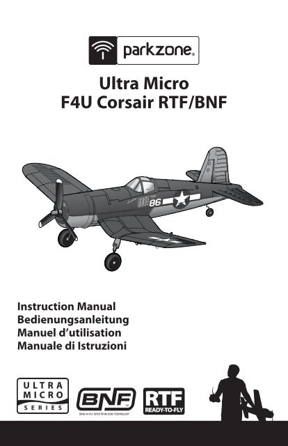
<strong>Ultra</strong> <strong>Micro</strong><br />
<strong>F4U</strong> <strong>Corsair</strong> <strong>RTF</strong>/<strong>BNF</strong><br />
Instruction Manual<br />
Bedienungsanleitung<br />
Manuel d’utilisation<br />
Manuale di Istruzioni
NOTICE<br />
All instructions, warranties and other collateral documents are subject to change at the sole<br />
discretion of Horizon Hobby, Inc. For up-to-date product literature, visit<br />
www.horizonhobby.com and click on the support tab for this product.<br />
Meaning of Special Language:<br />
The following terms are used throughout the product literature to indicate various levels of<br />
potential harm when operating this product:<br />
NOTICE: Procedures, which if not properly followed, create a possibility of physical<br />
property damage AND little or no possibility of injury.<br />
CAUTION: Procedures, which if not properly followed, create the probability of physical<br />
property damage AND a possibility of serious injury.<br />
WARNING: Procedures, which if not properly followed, create the probability of property<br />
damage, collateral damage, and serious injury OR create a high probability of<br />
superficial injury.<br />
WARNING: Read the ENTIRE instruction manual to become familiar with the features of<br />
the product before operating. Failure to operate the product correctly can result in damage<br />
to the product, personal property and cause serious injury.<br />
This is a sophisticated hobby product. It must be operated with caution and common sense<br />
and requires some basic mechanical ability. Failure to operate this Product in a safe and<br />
responsible manner could result in injury or damage to the product or other property. This<br />
product is not intended for use by children without direct adult supervision. Do not attempt<br />
disassembly, use with incompatible components or augment product in any way without<br />
the approval of Horizon Hobby, Inc. This manual contains instructions for safety, operation<br />
and maintenance. It is essential to read and follow all the instructions and warnings in the<br />
manual, prior to assembly, setup or use, in order to operate correctly and avoid damage or<br />
serious injury.<br />
Age Recommendation: Not for children under 14 years. This is not a toy.<br />
2 EN
Congratulations on your purchase of the finest ultra micro RC <strong>Corsair</strong> available. If you’ve flown<br />
the larger ParkZone <strong>Corsair</strong>, you’ll find this one flies sport aerobatics every bit as well, only in a<br />
much smaller space. Before you take the first flight, though, please take time to read through<br />
this manual. It has important pre-flight information that will help ensure your first flight is a<br />
great one.<br />
Table of Contents<br />
First Flight Preparation ......................................3<br />
Charging the Battery ..........................................4<br />
Battery Warnings .................................................5<br />
Low Voltage Cutoff (LVC) ..................................5<br />
Transmitter and Receiver Binding .................6<br />
Before Flight ..........................................................6<br />
Installing Transmitter Battery ..........................6<br />
Transmitter Control.............................................7<br />
Digital Trims ...........................................................7<br />
Dual Rate Function .............................................7<br />
Control Direction Test ........................................8<br />
Reverse Controls ..................................................9<br />
Control Centering ...............................................9<br />
Control Rates .......................................................10<br />
Settings for Control Horns .............................10<br />
Installing Flight Battery ...................................10<br />
Adjusting Center of Gravity (CG) ..................11<br />
Removing and Installing Landing Gear .....11<br />
Propeller and Propeller<br />
Shaft Maintenance ............................................12<br />
Removing and Installing the Propeller ......12<br />
Remove Propeller Shaft...................................12<br />
Installing Propeller Shaft ................................12<br />
Flying Tips and Repairs ....................................13<br />
Additional Safety Precautions<br />
and Warnings ......................................................14<br />
Maintenance After Flying ...............................14<br />
Troubleshooting Guide ...................................14<br />
Warranty and Repair Policy ............................16<br />
Warranty and Service Information ..............17<br />
FCC Information .................................................17<br />
Compliance Information for<br />
the European Union .........................................17<br />
Declaration of Conformity ............................18<br />
Instructions for disposal of WEEE<br />
by users in the European Union ...................18<br />
Replacement Parts ............................................70<br />
Optional Parts and Accessories ....................71<br />
Decal Application (Option 1) .........................72<br />
Decal Application (Option 2) .........................73<br />
Parts Contact Information ..............................74<br />
First Flight Preparation<br />
• Remove and inspect contents<br />
• Install batteries into battery charger<br />
• Begin charging the flight battery<br />
• Install batteries into the included<br />
transmitter (<strong>RTF</strong> ONLY)<br />
• Install fully charged flight battery into<br />
aircraft<br />
• Bind the receiver to a transmitter<br />
(<strong>BNF</strong> ONLY)<br />
<strong>F4U</strong> <strong>Corsair</strong> Specifications<br />
Wingspan<br />
15.9 in (405mm)<br />
Length 12.8 in (326mm)<br />
Weight 1.47 oz (41.8 g)<br />
<strong>F4U</strong> <strong>Corsair</strong> Features<br />
Onboard Electronics<br />
Spektrum AR6400 Receiver/Servos/<br />
ESC/ 2 SPMAS2000L Servos<br />
Battery<br />
150mAh 3.7V 12C Li-Po<br />
Charger<br />
1S 3.7V Li-Po Battery Charger<br />
Transmitter<br />
DSM 4-Channel Transmitter, 2.4GHz<br />
• Perform the Control Direction Test with the<br />
transmitter<br />
• Adjust flight controls and transmitter<br />
• Adjust battery for center of gravity (CG)<br />
• Perform a radio system Range Check<br />
• Find a safe and open area<br />
• Plan flight for flying field conditions<br />
Note: For Decal Application Options refer to<br />
the back of this manual.<br />
Bind-N-Fly<br />
Version<br />
Installed<br />
Included<br />
To register your product online, go to www.parkzone.com<br />
EN<br />
Included<br />
Sold Separately<br />
Ready-to -Fly<br />
Version<br />
Installed<br />
Included<br />
Included<br />
Included<br />
3
Charging the Battery<br />
Your <strong>F4U</strong> <strong>Corsair</strong> comes with a 1S 3.7V Li-Po<br />
Battery Charger and 1S Li-Po battery. It is<br />
important that you only charge with the<br />
included charger, or the E-flite® Celectra<br />
4-port Charger (EFLC1004). The flight battery<br />
will be required to confirm proper aircraft<br />
operation in future steps.<br />
The Battery Charging Process<br />
1. Charge only batteries that are cool to the touch and are not damaged. Look at the battery to<br />
make sure it is not damaged e.g., swollen, bent, broken or punctured.<br />
2. Remove the cover on the bottom of the charger and install four of the included AA batteries,<br />
noting proper polarity. Replace the cover after the AA batteries are installed.<br />
3. Slide the battery into the slot on the charger. The end cap of the battery is specifically designed<br />
to allow the battery to fit into the slot one way (usually with the label on the battery facing<br />
outward) to prevent reverse polarity connection. However, check for proper alignment and<br />
polarity before proceeding to the next step.<br />
4. Gently press the battery and its connector into the charge jack/connector located at the bottom<br />
of the slot in the charger.<br />
5. When you make the connection successfully, the LED on the charger turns solid red, indicating<br />
charging has begun.<br />
6. Charging a fully discharged (not over-discharged) 150mAh battery takes approximately 30–40<br />
minutes. As the battery nears full charge, the LED begins to blink.<br />
7. When the battery is fully charged, the LED blinks approximately every 20 seconds or goes out<br />
entirely. Note: If the LED stays on when the battery is removed, the AA batteries in the charger<br />
are low.<br />
8. Always unplug the battery from the charger immediately upon completion of charging.<br />
CAUTION: Overcharging a battery can cause a fire.<br />
CAUTION: Only use a charger specifically designed to charge a Li-Po battery. Failure to do<br />
so could result in fire causing injury or property damage.<br />
CAUTION: Only use an E-flite 6V power supply (EFLC1005) with this charger. DO NOT<br />
use a 12V power supply or property damage and injury could occur.<br />
4<br />
EN
Battery Warnings<br />
The Battery Charger (EFLC1003) included with<br />
the <strong>F4U</strong> <strong>Corsair</strong> has been designed to safely<br />
charge the Li-Po battery.<br />
CAUTION: All instructions and warnings<br />
must be followed exactly. Mishandling of Li-Po<br />
batteries can result in a fire, personal injury,<br />
and/or property damage.<br />
• By handling, charging or using the<br />
included Li-Po battery you assume all<br />
risks associated with lithium batteries.<br />
• If at any time the battery begins to<br />
balloon or swell, discontinue use<br />
immediately. If charging or discharging,<br />
discontinue and disconnect. Continuing<br />
to use, charge or discharge a battery that<br />
is ballooning or swelling can result in fire.<br />
• Always store the battery at room<br />
temperature in a dry area for best results.<br />
• Always transport or temporarily store the<br />
battery in a temperature range of<br />
40–120º F. Do not store battery or model<br />
in a car or direct sunlight. If stored in a<br />
hot car, the battery can be damaged or<br />
even catch fire.<br />
• Always charge batteries away from<br />
flammable materials.<br />
• NEVER USE AN Ni-Cd OR Ni-MH<br />
CHARGER.<br />
Failure to charge the battery with a<br />
compatible charger may cause fire<br />
resulting in personal injury and/or<br />
property damage<br />
• Never discharge Li-Po cells to below 3V<br />
under load.<br />
• Never cover warning labels with hook<br />
and loop strips.<br />
• Never leave charging batteries<br />
unattended.<br />
• Never charge batteries outside safe<br />
temperature range.<br />
• Never charge damaged batteries.<br />
Low Voltage Cutoff (LVC)<br />
When a Li-Po battery is discharged below<br />
3V, it will not hold a charge. The <strong>Corsair</strong> ESC<br />
protects the flight battery from over-discharge<br />
using Low Voltage Cutoff (LVC). Before the<br />
battery charge decreases too much, LVC<br />
removes power supply from the motor. Power<br />
to the motor quickly decreases and increases,<br />
showing some battery power is reserved for<br />
flight control and safe landing.<br />
When the motor power decreases then<br />
increases, please land the aircraft immediately<br />
and recharge the flight battery.<br />
Disconnect and remove the Li-Po battery<br />
from the aircraft after use to prevent trickle<br />
discharge. Before storage, charge the Li-Po<br />
battery to full capacity. During storage make<br />
sure battery charge does not go below 3V.<br />
NOTICE: Repeated flying to LVC will damage<br />
the battery.<br />
EN<br />
5
®<br />
<strong>RTF</strong><br />
Installing Transmitter Battery<br />
Your <strong>F4U</strong> <strong>Corsair</strong> <strong>RTF</strong> transmitter<br />
comes pre-bound to the aircraft,<br />
so binding should not be<br />
necessary. All that is needed to<br />
begin flying is installation of fully<br />
charged batteries in the aircraft<br />
and transmitter.<br />
1<br />
2<br />
3<br />
4<br />
6<br />
5<br />
Transmitter and Receiver Binding<br />
Binding is the process of programming the receiver of the control unit to recognize the GUID<br />
(Globally Unique Identifier) code of a single specific transmitter. You need to ‘bind’ your chosen<br />
Spektrum TM DSM® technology equipped aircraft transmitter to the receiver for proper operation.<br />
Note: For a list of compatible DSM® transmitters, please visit www.bindnfly.com.<br />
Note: When using a Futaba transmitter with a Spektrum DSM module, you will need to<br />
reverse the throttle channel.<br />
<br />
Binding Procedure Reference Table<br />
1. Refer to your transmitter’s unique instructions for binding to a receiver.<br />
2. Make sure the flight battery is disconnected from the airplane.<br />
3. Power off the transmitter.<br />
4. Connect the flight battery in the aircraft. The receiver LED will begin to<br />
flash (typically after 5 seconds).<br />
5. Put your transmitter into bind mode. If using the transmitter that is<br />
supplied with the <strong>RTF</strong> version, push the left control stick vertically into<br />
the case until it clicks, while powering on the transmitter.<br />
6. Make sure transmitter controls are neutral and throttle is in low position.<br />
7. After 5 to 10 seconds, the receiver status LED will become solid,<br />
indicating that the receiver is bound to the transmitter.<br />
Note: If the LED does not go to a solid light, refer to Troubleshooting<br />
Guide at back of manual.<br />
Before Flight<br />
1 2 3<br />
5<br />
6<br />
Lower throttle and throttle<br />
trim to lowest settings.<br />
Power on<br />
Transmitter<br />
Connect flight battery<br />
and attach to hook and<br />
loop strip.<br />
Wait 5<br />
Seconds<br />
Continuous LED<br />
CAUTION: Always keep hands away from propeller. When armed, the motor will turn the<br />
propeller in response to any throttle movement.<br />
6<br />
EN
<strong>RTF</strong><br />
Transmitter Control<br />
Mode 2<br />
Throttle/Rudder<br />
Elevator/Aileron<br />
Rudder Trim<br />
Aileron Trim<br />
Throttle Trim<br />
Elevator Trim<br />
Mode 1<br />
Elevator/Rudder<br />
Throttle/Aileron<br />
Rudder Trim<br />
Aileron Trim<br />
Elevator Trim<br />
Throttle Trim<br />
Digital Trims<br />
The ParkZone® 4-channel 2.4GHz DSM transmitter features digital trim buttons on all controls to<br />
make fine adjustments. The digital trims are used to fine–tune the model’s flight path when<br />
in flight.<br />
Note: Before the first flight, center the control surfaces mechanically (see Control Centering).<br />
Note: When pressed down, trim buttons make a sound that increases or decreases in pitch at<br />
each pressing. The middle or neutral trim position is heard as a middle tone in the pitch range of<br />
the sounds. The end of the control range is sounded by a series of beeps.<br />
Dual Rate Function<br />
This transmitter’s dual rate feature lets the pilot change between high and low control rates for<br />
the aileron, elevator, rudder.<br />
• When powered on, this transmitter is automatically in high-rate mode.<br />
• Change rate modes by pushing the right-hand control stick vertically into the case until it<br />
clicks while the transmitter is powered on.<br />
• High-rate mode is shown by the transmitter’s LED glowing solid red. In high-rate mode the<br />
controls can reach their maximum values. This mode is typically preferred by experienced<br />
pilots for maximum control authority.<br />
• Low-rate mode is shown by the transmitter’s LED blinking continuously. In low-rate mode<br />
the controls are reduced to approximately 70% of their maximum values. This mode is<br />
typically preferred by (and best for) first-time, low-time and other pilots interested in<br />
smoother and more easily controlled flight.<br />
EN<br />
7
Control Direction Test<br />
Bind your aircraft and transmitter before doing these tests. Move the controls on the transmitter<br />
to make sure aircraft control surfaces move correctly (Mode 2 shown).<br />
Down<br />
Elevator<br />
Up<br />
Elevator<br />
Left<br />
Aileron<br />
Right<br />
Aileron<br />
Left<br />
Rudder<br />
Right<br />
Rudder<br />
8 EN
Reverse Controls<br />
NOTICE: The <strong>Corsair</strong> <strong>RTF</strong> should not require any servo reversing. Should the <strong>F4U</strong> <strong>Corsair</strong>’s<br />
electronic components be used in another aircraft, you may find it necessary to reverse the<br />
operation of the flight control surfaces.<br />
D<br />
C<br />
A<br />
B<br />
F<br />
E<br />
A<br />
B<br />
C<br />
D<br />
E<br />
F<br />
Rudder Reversed<br />
Rudder Normal<br />
Elevator Reversed<br />
Elevator Normal<br />
Aileron Reversed<br />
Aileron Normal<br />
The transmitter included with the <strong>F4U</strong> <strong>Corsair</strong><br />
is the same transmitter included in other <strong>Ultra</strong><br />
<strong>Micro</strong> <strong>RTF</strong> models. It also functions identically<br />
to the transmitter included with the E-flite<br />
mCX and mSR.<br />
1. Be certain the battery is unplugged from<br />
the aircraft and the transmitter is turned off.<br />
2. Press and hold the digital trim button for<br />
the surface you would like to reverse.<br />
3. While holding the digital trim button, turn<br />
the transmitter on.<br />
4. Hold the digital trim buttons down for<br />
approximately 5 seconds until you hear a<br />
tone, confirming the selection.<br />
5. Connect the flight battery and complete<br />
the flight control test. Confirm all surfaces<br />
operate in the correct direction.<br />
Control Centering<br />
Before first flights, or in the event of an<br />
accident, make sure the flight control surfaces<br />
are centered. Adjust linkages mechanically if<br />
control surfaces are not centered.<br />
Use of the transmitter trims may not correctly<br />
center the aircraft control surfaces due to the<br />
mechanical limits of linear servos.<br />
1. Make sure control surfaces are neutral<br />
when the transmitter controls and trims are<br />
centered. Where possible, transmitter<br />
sub-trim must be set to zero.<br />
2. When needed, use a pair of pliers to<br />
carefully bend the metal of the linkage<br />
(see illustration).<br />
3. Make the U-shape narrower to make the<br />
connector shorter. Make the U-shape wider<br />
to make the linkage longer.<br />
Note: If using any other transmitter that has programmable features, do not use Sub-Trim<br />
to adjust the center position of the servo, and never set Travel Adjust values above 100%.<br />
<strong>Ultra</strong> <strong>Micro</strong> servos are unique in that they are calibrated to reach maximum travel at 100%.<br />
Increasing the value above 100% will NOT result in more travel, but can cause the servo to<br />
lock and will result in poor flight characteristics or a crash.<br />
Note: There are two aileron servos located on the underside of the wings.<br />
EN<br />
9
Control Rates<br />
We recommend using a DSM aircraft transmitter<br />
capable of dual rates. Adjust according<br />
to individual preferences after initial flight.<br />
It is normal for linear servos to make noise.<br />
The noise is not an indication of a faulty servo.<br />
To achieve the proper Low Rate settings<br />
when using a programmable DSM aircraft<br />
transmitter, set the low rate value to 70% for<br />
aileron, elevator and rudder.<br />
High Rate Low Rate<br />
Aileron 6mm up/down 4mm up/down<br />
Elevator 4mm up/down 3mm up/down<br />
Rudder 7mm up/down 5mm up/down<br />
Note: All control surfaces are measured at the<br />
widest point.<br />
Settings for Control Horns<br />
Aileron Elevator Rudder<br />
The illustration shows factory settings for<br />
linkages on control horns. After flying, if you<br />
want more or less control throw, carefully<br />
adjust linkage positions for desired control<br />
response. (Picture not to scale.)<br />
Installing Flight Battery<br />
1. Connect fully charged flight battery to the<br />
aircraft, noting proper polarity.<br />
2. Attach flight battery to a strip of loop<br />
fastener on the bottom of the fuselage.<br />
10<br />
EN
Adjusting Center of Gravity (CG)<br />
The CG location is 28mm back from leading<br />
edge of the wing at the root. This CG location<br />
has been determined with the included 1S<br />
150mAh 3.7V Li-Po battery installed in the<br />
front of the battery cavity.<br />
Note: The battery cavity is oversized to allow for Center of Gravity adjustment. Start by<br />
placing the battery in the front of the cavity and adjust as necessary.<br />
28mm<br />
Removing and Installing Landing Gear<br />
To Remove:<br />
1. Lift the end of the landing gear wire above<br />
the stop.<br />
To Install:<br />
1. Gently slide the landing gear into the plastic<br />
clips on the bottom of the wing.<br />
2. Gently pull the landing gear toward the<br />
center of the wing and away from the clips.<br />
2. The landing gear is installed when the end<br />
of the landing gear wire is inside the stop.<br />
Note: Install left and right gear with the vertical strut of the landing gear toward the front of<br />
the wing. Install the bent wire of each strut fully inside each mount.<br />
EN<br />
11
Propeller and Propeller Shaft Maintenance<br />
CAUTION: DO NOT handle propeller<br />
parts while the flight battery is connected.<br />
Personal injury could result.<br />
Removing and Installing the<br />
Propeller<br />
2. While the fuselage is open, hold the white<br />
nylon nut on the prop shaft using needlenose<br />
pliers or hemostats.<br />
1. Hold the shaft using needle-nose pliers<br />
or hemostats.<br />
Remove<br />
Install<br />
3. Turn the spur gear on the prop shaft<br />
clockwise (looking from front of model) to<br />
remove the nut.<br />
4. Gently pull the shaft from the gearbox.<br />
Make sure washer and 2 bushings are not<br />
lost when shaft is removed from gearbox.<br />
2. Turn propeller counterclockwise (looking<br />
from front of model) to remove. (Turn the<br />
propeller clockwise to install.)<br />
Note: You may also choose to use a<br />
130mm x 70mm 2-blade propeller (EFL9051)<br />
for a bit more performance from your model.<br />
Installing Propeller Shaft<br />
1. Push the prop shaft into the gearbox.<br />
2. Hold the nylon nut on the back of the<br />
prop shaft.<br />
3. Turn the spur gear counterclockwise<br />
(looking from front of model) until the nut<br />
is fully installed. Please ensure the prop<br />
shaft turns freely before moving on.<br />
4. Assemble the fuselage with clear tape.<br />
3. Carefully remove glued spinner from<br />
propeller. You may need to cut glue from<br />
the propeller. (To reinstall the spinner use<br />
a drop of CA or Foam-Compatible CA.)<br />
Remove Propeller Shaft<br />
1. Cut open the fuselage at the decal on one<br />
side of the fuselage and on the turtle deck<br />
(top of fuselage in front of canopy).<br />
Note: Numbers on the propeller must face out<br />
for correct propeller operation.<br />
Note: Removing tape or decals will remove<br />
paint from the fuselage.<br />
12<br />
EN
Flying Tips and Repairs<br />
Flying<br />
We recommend only flying your <strong>F4U</strong> <strong>Corsair</strong><br />
in light winds. Always avoid flying near houses,<br />
trees, wires and buildings. You should also<br />
be careful to avoid flying in areas where there<br />
are many people, such as busy parks, schoolyards,<br />
or soccer fields. Consult local laws and<br />
ordinances before choosing a location to fly<br />
your aircraft.<br />
Place the <strong>F4U</strong> <strong>Corsair</strong> in position for takeoff<br />
(facing into the wind if flying outdoors).<br />
Gradually increase the throttle to ¾ to full, and<br />
steer with the rudder. Pull back gently with<br />
the elevator and climb to check trim. Once<br />
the trim is adjusted, begin exploring the flight<br />
envelope of the <strong>F4U</strong> <strong>Corsair</strong>.<br />
Note: Due to the large propeller on the <strong>F4U</strong><br />
<strong>Corsair</strong>, it is possible to hit the prop on the<br />
ground while landing. Make sure to flare<br />
when landing and try to land as smoothly<br />
as possible to minimize hitting the prop.<br />
While this does not damage the airplane it is<br />
possible to wear down the<br />
tips of the propeller if flying<br />
from an abrasive surface<br />
such as concrete or asphalt.<br />
Failure to lower the throttle<br />
stick and trim to the lowest<br />
possible positions during a<br />
crash could result in damage<br />
to the ESC in the receiver<br />
unit, which may require replacement.<br />
Always<br />
decrease throttle at<br />
propeller strike.<br />
Note: Crash damage is not covered under<br />
warranty.<br />
Repairs<br />
Repair the <strong>Corsair</strong> using foam-compatible CA<br />
glue or clear tape. Only use foam-compatible<br />
CA glue, as other types of glue can damage<br />
the foam. When parts are not repairable, see<br />
the Replacement Parts List for ordering by<br />
item number.<br />
Note: For a listing of all replacement and<br />
optional parts, refer to the list at the back of<br />
this manual.<br />
EN<br />
13
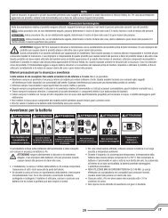
Additional Safety Precautions and Warnings<br />
As the user of this product, you are solely<br />
responsible for operating in a manner that<br />
does not endanger yourself and others<br />
or result in damage to the product or the<br />
property of others.<br />
This model is controlled by a radio signal<br />
subject to interference from many sources<br />
outside your control. This interference can<br />
cause momentary loss of control so it is<br />
advisable to always keep a safe distance in all<br />
directions around your model, as this margin<br />
will help avoid collisions or injury.<br />
• Always keep a safe distance in all directions around your model to avoid collisions or injury.<br />
This model is controlled by a radio signal subject to interference from many sources outside<br />
your control. Interference can cause momentary loss of control<br />
• Always operate your model in open spaces away from full-size vehicles, traffic and people.<br />
• Always carefully follow the directions and warnings for this and any optional support<br />
equipment (chargers, rechargeable battery packs, etc.).<br />
• Always keep all chemicals, small parts and anything electrical out of the reach of children.<br />
• Always avoid water exposure to all equipment not specifically designed and protected for<br />
this purpose. Moisture causes damage to electronics.<br />
• Never place any portion of the model in your mouth as it could cause serious injury or even<br />
death.<br />
• Never operate your model with low transmitter batteries.<br />
Maintenance After Flying<br />
• Disconnect flight battery from Receiver/<br />
ESC (Required for Safety)<br />
• Power off transmitter<br />
• Remove flight battery from aircraft<br />
• Recharge flight battery<br />
• Repair or replace all damaged parts<br />
• Store flight battery apart from aircraft<br />
and monitor the battery charge<br />
• Make note of flight conditions and flight<br />
plan results, planning for future flights<br />
Troubleshooting Guide<br />
Problem Possible Cause Solution<br />
Aircraft will not respond<br />
to throttle but responds to<br />
other controls<br />
Extra propeller noise or<br />
extra vibration<br />
Reduced flight time or<br />
aircraft underpowered<br />
Throttle stick and/or throttle trim too high<br />
Throttle channel is reversed<br />
Motor unplugged from receiver<br />
Damaged propeller, spinner, prop shaft or motor<br />
Nut on prop shaft is too loose<br />
Flight battery charge is low<br />
Propeller installed backwards<br />
Flight battery damaged<br />
Flight conditions may be too cold<br />
Battery capacity too low for flight conditions<br />
Reset controls with throttle stick and throttle trim at<br />
lowest setting<br />
Reverse throttle channel on transmitter<br />
Open fuselage and ensure the plug for the motor is<br />
properly installed<br />
Replace damaged parts<br />
Tighten the prop shaft nut 1/2 turn<br />
Completely recharge flight battery<br />
Install propeller with numbers facing forward<br />
Replace flight battery and follow flight battery<br />
instructions<br />
Make sure battery is warm before use<br />
Replace battery or use a larger capacity battery<br />
14<br />
EN
Problem Possible Cause Solution<br />
LED on receiver flashes<br />
and aircraft will not bind<br />
to transmitter (during<br />
binding)<br />
LED on receiver flashes<br />
rapidly and aircraft will<br />
not respond to transmitter<br />
(after binding)<br />
Control surface does not<br />
move<br />
Transmitter too near aircraft during binding<br />
process<br />
Bind switch or button not held long enough<br />
during bind process<br />
Less than a 5-second wait between first<br />
powering on transmitter and connecting flight<br />
battery to aircraft<br />
Aircraft bound to different model memory<br />
(ModelMatch TM radios only)<br />
Flight battery/transmitter battery charge is<br />
too low<br />
Control surface, control horn, linkage or<br />
servo damage<br />
Wire damaged or connections loose<br />
Flight battery charge is low<br />
Control linkage does not move freely<br />
Power off transmitter, move transmitter a larger<br />
distance from aircraft, disconnect and reconnect flight<br />
battery to aircraft and follow binding instructions<br />
Power off transmitter and repeat bind process. Hold<br />
transmitter bind button or switch until receiver is<br />
bound<br />
Leaving transmitter on, disconnect and reconnect<br />
flight battery to aircraft<br />
Select correct model memory on transmitter and<br />
disconnect and reconnect flight battery to aircraft<br />
Replace/recharge batteries<br />
Replace or repair damaged parts and adjust controls<br />
Do a check of wires and connections, connect or<br />
replace as needed<br />
Fully recharge flight battery<br />
Make sure control linkage moves freely<br />
Controls reversed Transmitter settings reversed Do the Control Direction Test and adjust controls on<br />
transmitter appropriately<br />
Motor loses power<br />
Motor power quickly<br />
decreases and increases<br />
then motor loses power<br />
Servo locks or freezes at<br />
full travel<br />
Damage to motor, propeller shaft or power<br />
components<br />
Nut on prop shaft is too tight<br />
Battery power is down to the point of receiver/<br />
ESC Low Voltage Cutoff (LVC)<br />
Travel adjust value is set above 100%<br />
overdriving the servo<br />
Do a check of motor, prop shaft and power<br />
components for damage (replace as needed)<br />
Loosen prop shaft nut until propeller shaft turns freely<br />
Recharge flight battery or replace battery that is no<br />
longer performing<br />
Set Travel adjust to 100% or less<br />
EN<br />
15
Warranty and Repair Policy<br />
Warranty Period<br />
Exclusive Warranty- Horizon Hobby, Inc., (Horizon) warranties<br />
that the Products purchased (the “Product”) will be free from<br />
defects in materials and workmanship at the date of purchase<br />
by the Purchaser.<br />
Limited Warranty<br />
Horizon reserves the right to change or modify this<br />
warranty without notice and disclaims all other warranties,<br />
express or implied.<br />
(a) This warranty is limited to the original Purchaser<br />
(“Purchaser”) and is not transferable. REPAIR OR<br />
REPLACEMENT AS PROVIDED UNDER THIS WARRANTY<br />
IS THE EXCLUSIVE REMEDY OF THE PURCHASER. This<br />
warranty covers only those Products purchased from<br />
an authorized Horizon dealer. Third party transactions<br />
are not covered by this warranty. Proof of purchase is<br />
required for all warranty claims.<br />
(b) Limitations- HORIZON MAKES NO WARRANTY OR<br />
REPRESENTATION, EXPRESS OR IMPLIED, ABOUT<br />
NON-INFRINGEMENT, MERCHANTABILITY OR FITNESS FOR A<br />
PARTICULAR PURPOSE OF THE PRODUCT. THE PURCHASER<br />
ACKNOWLEDGES THAT THEY ALONE HAVE DETERMINED THAT<br />
THE PRODUCT WILL SUITABLY MEET THE REQUIREMENTS OF<br />
THE PURCHASER’S INTENDED USE.<br />
(c) Purchaser Remedy- Horizon’s sole obligation hereunder<br />
shall be that Horizon will, at its option, (i) repair or (ii)<br />
replace, any Product determined by Horizon to be<br />
defective. In the event of a defect, these are the Purchaser’s<br />
exclusive remedies. Horizon reserves the right to inspect<br />
any and all equipment involved in a warranty claim. Repair<br />
or replacement decisions are at the sole discretion of<br />
Horizon. This warranty does not cover cosmetic damage or<br />
damage due to acts of God, accident, misuse, abuse,<br />
negligence, commercial use, or modification of or to any<br />
part of the Product.<br />
This warranty does not cover damage due to improper installation,<br />
operation, maintenance, or attempted repair by anyone<br />
other than Horizon. Return of any Product by Purchaser must<br />
be approved in writing by Horizon before shipment.<br />
Damage Limits<br />
HORIZON SHALL NOT BE LIABLE FOR SPECIAL, INDIRECT OR<br />
CONSEQUENTIAL DAMAGES, LOSS OF PROFITS OR PRODUCTION<br />
OR COMMERCIAL LOSS IN ANY WAY CONNECTED WITH THE<br />
PRODUCT, WHETHER SUCH CLAIM IS BASED IN CONTRACT,<br />
WARRANTY, NEGLIGENCE, OR STRICT LIABILITY. Further, in no<br />
event shall the liability of Horizon exceed the individual price<br />
of the Product on which liability is asserted. As Horizon has no<br />
control over use, setup, final assembly, modification or misuse,<br />
no liability shall be assumed nor accepted for any resulting<br />
damage or injury. By the act of use, setup or assembly, the<br />
user accepts all resulting liability.<br />
If you as the Purchaser or user are not prepared to accept<br />
the liability associated with the use of this Product, you are<br />
advised to return this Product immediately in new and unused<br />
condition to the place of purchase.<br />
Law: These Terms are governed by Illinois law (without regard<br />
to conflict of law principals).<br />
Warranty Services<br />
Questions, Assistance, and Repairs<br />
Your local hobby store and/or place of purchase cannot provide<br />
warranty support or repair. Once assembly, setup or use of the<br />
Product has been started, you must contact Horizon directly.<br />
This will enable Horizon to better answer your questions and<br />
service you in the event that you may need any assistance. For<br />
questions or assistance, please direct your email to productsupport@horizonhobby.com,<br />
or call 877.504.0233 toll free to<br />
speak to a Product Support representative. You may also find<br />
information on our website at www.horizonhobby.com.<br />
Inspection or Repairs<br />
If this Product needs to be inspected or repaired, please use<br />
the Horizon Online Repair Request submission process found<br />
on our website or call Horizon to obtain a Return Merchandise<br />
Authorization (RMA) number. Pack the Product securely<br />
using a shipping carton. Please note that original boxes may<br />
be included, but are not designed to withstand the rigors of<br />
shipping without additional protection. Ship via a carrier that<br />
provides tracking and insurance for lost or damaged parcels, as<br />
Horizon is not responsible for merchandise until it arrives and<br />
is accepted at our facility. An Online Repair Request is available<br />
at www.horizonhobby.com http://www.horizonhobby.<br />
com under the Repairs tab. If you do not have internet access,<br />
please contact Horizon Product Support to obtain a RMA<br />
number along with instructions for submitting your product<br />
for repair. When calling Horizon, you will be asked to provide<br />
your complete name, street address, email address and phone<br />
number where you can be reached during business hours.<br />
When sending product into Horizon, please include your RMA<br />
number, a list of the included items, and a brief summary<br />
of the problem. A copy of your original sales receipt must<br />
be included for warranty consideration. Be sure your name,<br />
address, and RMA number are clearly written on the outside of<br />
the shipping carton.<br />
Notice: Do not ship batteries to Horizon. If you have any<br />
issue with a battery, please contact the appropriate<br />
Horizon Product Support office.<br />
Warranty Inspection and Repairs<br />
To receive warranty service, you must include your original<br />
sales receipt verifying the proof-of-purchase date. Provided<br />
warranty conditions have been met, your Product will be repaired<br />
or replaced free of charge. Repair or replacement decisions are at<br />
the sole discretion of Horizon Hobby.<br />
Non-Warranty Repairs<br />
Should your repair not be covered by warranty the<br />
repair will be completed and payment will be required<br />
without notification or estimate of the expense unless<br />
the expense exceeds 50% of the retail purchase cost. By<br />
submitting the item for repair you are agreeing to payment of<br />
the repair without notification. Repair estimates are available<br />
upon request. You must include this request with your repair.<br />
Non-warranty repair estimates will be billed a minimum of ½<br />
hour of labor. In addition you will be billed for return freight.<br />
Horizon accepts money orders and cashiers checks, as well as<br />
Visa, MasterCard, American Express, and Discover cards. By<br />
submitting any item to Horizon for inspection or repair, you<br />
are agreeing to Horizon’s Terms and Conditions found on our<br />
website under the Repairs tab.<br />
16<br />
EN
Warranty and Service Information<br />
Country of Purchase Horizon Hobby Address Phone Number/Email Address<br />
United States<br />
of America<br />
United Kingdom<br />
Germany<br />
France<br />
Horizon Service Center<br />
(Electronics and engines)<br />
Horizon Product Support<br />
(All other products)<br />
Horizon Hobby Limited<br />
Horizon Technischer<br />
Service<br />
Horizon Hobby SAS<br />
FCC Information<br />
4105 Fieldstone Rd<br />
Champaign, Illinois<br />
61822 <strong>USA</strong><br />
4105 Fieldstone Rd<br />
Champaign, Illinois<br />
61822 <strong>USA</strong><br />
Units 1-4 Ployters Rd<br />
Staple Tye<br />
Harlow, Essex<br />
CM18 7NS<br />
United Kingdom<br />
Hamburger Str. 10<br />
25335 Elmshorn, Germany<br />
14 Rue Gustave Eiffel<br />
Zone d’Activité du Réveil Matin<br />
91230 Montgeron<br />
877-504-0233<br />
Online Repair Request visit:<br />
www.horizonhobby.com/repairs<br />
877-504-0233<br />
productsupport@horizonhobby.com<br />
+44 (0) 1279 641 097<br />
sales@horizonhobby.co.uk<br />
+49 4121 46199 66<br />
service@horizonhobby.de<br />
+33 (0) 1 60 47 44 70<br />
infofrance@horizonhobby.com<br />
This device complies with part 15 of the FCC rules. Operation is subject to the following two<br />
conditions: (1)This device may not cause harmful interference, and (2) this device must accept<br />
any interference received, including interference that may cause undesired operation.<br />
CAUTION: Changes or modifications not expressly approved by the party responsible for<br />
compliance could void the user’s authority to operate the equipment.<br />
This product contains a radio transmitter with wireless technology which has been tested and<br />
found to be compliant with the applicable regulations governing a radio transmitter in the<br />
2.400GHz to 2.4835GHz frequency range.<br />
Compliance Information for the European Union<br />
Declaration of Conformity<br />
(in accordance with ISO/IEC 17050-1)<br />
No. HH2011022802<br />
Product(s):<br />
PKZ <strong>Ultra</strong> <strong>Micro</strong> <strong>F4U</strong> <strong>Corsair</strong> <strong>RTF</strong><br />
Item Number(s):<br />
PKZ1600<br />
Equipment class: 1<br />
The object of declaration described above is in conformity with the requirements of the<br />
specifications listed below, following the provisions of the European R&TTE directive 1999/5/EC<br />
and EMC Directive 2004/108/EC<br />
EN 300-328 V1.7.1<br />
EN 301 489-1 V1.7.1: 2006<br />
EN 301 489-17 V1.3.2: 2008<br />
EN 60950-1:2006+A11<br />
EN55022: 2006,<br />
EN55024: 1998+A1: 2001+A2: 2003<br />
(EN61000-4-2: 2001, EN61000-4-3: 2006, EN61000-4-8: 2001)<br />
Signed for and on behalf of:<br />
Horizon Hobby, Inc.<br />
Champaign, IL <strong>USA</strong><br />
Feb. 28, 2011<br />
EN<br />
Steven A. Hall<br />
Vice President<br />
International Operations and Risk Management<br />
Horizon Hobby, Inc.<br />
17
Declaration of Conformity<br />
(in accordance with ISO/IEC 17050-1)<br />
No. HH2011022801<br />
Product(s):<br />
PKZ <strong>Ultra</strong>-<strong>Micro</strong> <strong>F4U</strong> <strong>Corsair</strong> <strong>BNF</strong><br />
Item Number(s):<br />
PKZ1680<br />
Equipment class: 1<br />
The object of declaration described above is in conformity with the requirements of the<br />
specifications listed below, following the provisions of the European R&TTE directive 1999/5/EC<br />
and EMC Directive 2004/108/EC<br />
EN 301 489-1 V1.7.1: 2006<br />
EN 301 489-17 V1.3.2: 2008<br />
EN55022: 2006,<br />
EN55024: 1998+A1: 2001+A2: 2003<br />
(EN61000-4-2: 2001, EN61000-4-3: 2006, EN61000-4-8: 2001)<br />
Signed for and on behalf of:<br />
Horizon Hobby, Inc.<br />
Champaign, IL <strong>USA</strong><br />
Feb. 28, 2011<br />
Steven A. Hall<br />
Vice President<br />
International Operations and Risk Management<br />
Horizon Hobby, Inc.<br />
Instructions for disposal of WEEE by users in the European Union<br />
This product must not be disposed of with other waste. Instead, it is the user’s<br />
responsibility to dispose of their waste equipment by handing it over to a<br />
designated collections point for the recycling of waste electrical and electronic<br />
equipment. The separate collection and recycling of your waste equipment at the<br />
time of disposal will help to conserve natural resources and ensure that it is recycled<br />
in a manner that protects human health and the environment. For more information about<br />
where you can drop off your waste equipment for recycling, please contact your local city office,<br />
your household waste disposal service or where you purchased the product.<br />
18 EN
Replacement Parts • Ersatzteile • Pièces de rechange<br />
• Pezzi di ricambio<br />
Part # | Nummer<br />
Numéro | Codice<br />
PKZU1602<br />
PKZU1603<br />
PKZU1604<br />
PKZU1608<br />
PKZU1620<br />
PKZU1622<br />
PKZU1625<br />
PKZU1626<br />
PKZU1667<br />
HBZ4929<br />
PKZ3528<br />
PKZ3616<br />
EFLC1003<br />
PKZ3341<br />
EFLUP11803B<br />
EFLB1501S<br />
EFLH1067<br />
EFLH1066<br />
Description Beschreibung Description Descrizione<br />
Decal Sheet:<br />
UM <strong>F4U</strong> <strong>Corsair</strong><br />
Landing Gear Set:<br />
UM <strong>F4U</strong> <strong>Corsair</strong><br />
Clear Canopy:<br />
UM <strong>F4U</strong> <strong>Corsair</strong><br />
Spinner: UM <strong>F4U</strong><br />
<strong>Corsair</strong> (4)<br />
Wing/Belly Pan<br />
Without Servo:<br />
UM <strong>F4U</strong> <strong>Corsair</strong><br />
Aileron Pushrod<br />
Linkage:<br />
UM <strong>F4U</strong> <strong>Corsair</strong><br />
Complete Tail Set:<br />
UM <strong>F4U</strong> <strong>Corsair</strong><br />
Elevator/Rudder<br />
Pushrod Set:<br />
UM <strong>F4U</strong> <strong>Corsair</strong><br />
Bare Fuselage with<br />
Canopy: UM <strong>F4U</strong><br />
<strong>Corsair</strong><br />
Gearbox (No Motor):<br />
Champ, UM T28,<br />
<strong>Corsair</strong><br />
Propeller Shaft:<br />
Sukhoi Su-26m,<br />
<strong>Micro</strong> P-51<br />
Motor: <strong>Ultra</strong> <strong>Micro</strong><br />
P-51, UM T-28<br />
DC 3.7V Li-Po<br />
Charger<br />
2.4GHz Transmitter<br />
DSM2: Vapor<br />
110 x 80mm 3 Blade<br />
Propeller<br />
1S 3.7V 150mAh<br />
Li-Po Battery<br />
Replacement Servo<br />
Retaining Collars<br />
Replacement Servo<br />
Mechanics: MCX/2/<br />
MSR/FHX/MH-35<br />
Dekorbogen:<br />
UM <strong>F4U</strong> <strong>Corsair</strong><br />
Fahrgestellsatz:<br />
UM <strong>F4U</strong> <strong>Corsair</strong><br />
Durchsichtige<br />
Kabinenhaube:<br />
UM <strong>F4U</strong> <strong>Corsair</strong><br />
Spinner: UM <strong>F4U</strong><br />
<strong>Corsair</strong> (4)<br />
Flügel / untere Verkleidung<br />
ohne Servo:<br />
UM <strong>F4U</strong> <strong>Corsair</strong><br />
Querrudergestänge:<br />
UM <strong>F4U</strong> <strong>Corsair</strong><br />
Vollständiger Hecksatz:<br />
UM <strong>F4U</strong> <strong>Corsair</strong><br />
Höhen-/Seitenrudergestängesatz:<br />
UM <strong>F4U</strong> <strong>Corsair</strong><br />
Blank Rumpf mit<br />
Kabinenhaube: UM<br />
<strong>F4U</strong> <strong>Corsair</strong><br />
Getriebe (ohne Motor):<br />
Champ, UM T28,<br />
<strong>Corsair</strong><br />
Propellerwelle:<br />
Sukhoi Su-26m,<br />
<strong>Micro</strong> P-51<br />
Motor: <strong>Ultra</strong> <strong>Micro</strong><br />
P-51, UM T-28<br />
DC-3,7V-Li-Po-<br />
Ladegerät<br />
2,4GHz-DSM2-<br />
Sender: Vapor<br />
110 x 80 mm-<br />
3-Blattpropeller<br />
1S-3,7V-150mAh-Li-<br />
Po-Akku<br />
Ersatzsicherung für<br />
Servo<br />
Ersatz-Servomechanik:<br />
MCX/2/MSR/FHX/<br />
MH-35<br />
Planche de décalcomanies<br />
: UM <strong>F4U</strong><br />
<strong>Corsair</strong><br />
Jeu de train<br />
d’atterrissage :<br />
UM <strong>F4U</strong> <strong>Corsair</strong><br />
Verrière transparente<br />
: UM <strong>F4U</strong> <strong>Corsair</strong><br />
Cône d’hélice :<br />
UM <strong>F4U</strong> <strong>Corsair</strong> (4)<br />
Aile/blindage inférieur<br />
sans servo :<br />
UM <strong>F4U</strong> <strong>Corsair</strong><br />
Liaison de commande<br />
d’aileron :<br />
UM <strong>F4U</strong> <strong>Corsair</strong><br />
Queue complète :<br />
UM <strong>F4U</strong> <strong>Corsair</strong><br />
Jeu de biellettes<br />
mécaniques de<br />
gouverne de profondeur<br />
et de direction :<br />
UM <strong>F4U</strong> <strong>Corsair</strong><br />
Fuselage nu avec<br />
verrière : UM <strong>F4U</strong><br />
<strong>Corsair</strong><br />
Réducteur (sans<br />
moteur) : Champ,<br />
UM T28, <strong>Corsair</strong><br />
Arbre d’hélice :<br />
Sukhoi Su-26m,<br />
<strong>Micro</strong> P-51<br />
Moteur : <strong>Ultra</strong> <strong>Micro</strong><br />
P-51, UM T-28<br />
Chargeur Li-Po<br />
DC 3,7 V<br />
Émetteur DSM2<br />
2,4 GHz : Vapor<br />
Hélice 3 pales<br />
110 x 80 mm<br />
Batterie Li-Po<br />
150 mAh 3,7 V 1S<br />
Bagues de maintien<br />
de servo de rechange<br />
Pièces de rechange<br />
mécaniques servo :<br />
MCX/2/MSR/FHX/<br />
MH-35<br />
Foglio con<br />
decalcomanie:<br />
UM <strong>F4U</strong> <strong>Corsair</strong><br />
Set carrello di<br />
atterraggio:<br />
UM <strong>F4U</strong> <strong>Corsair</strong><br />
Capottina trasparente:<br />
UM <strong>F4U</strong> <strong>Corsair</strong><br />
Ogiva:<br />
UM <strong>F4U</strong> <strong>Corsair</strong> (4)<br />
Carenatura ala/<br />
inferiore, senza servo:<br />
UM <strong>F4U</strong> <strong>Corsair</strong><br />
Leveraggio asta di<br />
comando dell’alettone:<br />
UM <strong>F4U</strong> <strong>Corsair</strong><br />
Set completo coda:<br />
UM <strong>F4U</strong> <strong>Corsair</strong><br />
Set asta di comando<br />
elevatore/timone:<br />
UM <strong>F4U</strong> <strong>Corsair</strong><br />
Fusoliera semplice<br />
con capottina:<br />
UM <strong>F4U</strong> <strong>Corsair</strong><br />
Riduttore (senza<br />
motore): Champ,<br />
UM T28, <strong>Corsair</strong><br />
Albero dell’elica:<br />
Sukhoi Su-26m,<br />
<strong>Micro</strong> P-51<br />
Motore <strong>Ultra</strong> <strong>Micro</strong><br />
P-51, UM T-28<br />
Caricabatterie<br />
Li-Po CC da 3,7 V<br />
Trasmettitore DSM2<br />
da 2,4 GHz: Vapor<br />
Elica 110 x 80 mm<br />
a 3 lame<br />
Batteria Li-Po 1S da<br />
3,7 V, 150 mAh<br />
Collarini di fissaggio<br />
del servo di ricambio<br />
Componenti meccanici<br />
di ricambio del servo:<br />
MCX/2/MSR/FHX/<br />
MH-35<br />
70
Optional Parts and Accessories • Optionale Bauteile und Zubehör •<br />
Pièces et accessoires optionnels • Componenti e accessori opzionali<br />
Part # | Nummer<br />
Numéro | Codice<br />
EFL9054<br />
SPMAR6400<br />
SPMAS2000L<br />
SPM6832<br />
EFL9051<br />
EFLC1004<br />
EFLC1005<br />
EFLC1005AU<br />
EFLC1005EU<br />
EFLC1005UK<br />
SPMR6610<br />
SPMR66101<br />
SPMR6610E<br />
SPMR66101E<br />
SPMR8800<br />
SPMR8800EU<br />
SPMR88001AU<br />
SPMR88001EU<br />
Description Beschreibung Description Descrizione<br />
Prop Shaft with<br />
Gear (2): UMX 4Site<br />
AR6400 DSM2<br />
6-Channel <strong>Ultra</strong><br />
<strong>Micro</strong> Receiver/ESC<br />
1.7-Gram Linear<br />
Long Throw Servo<br />
Replacement Servo<br />
Mechanics: <strong>Ultra</strong><br />
<strong>Micro</strong> Long Throw<br />
Prop and Spinner<br />
130x70 (2): UM<br />
4-Site/Champ<br />
Celectra 4-Port 1S<br />
3.7V 0.3A DC Li-Po<br />
Charger<br />
AC to 6VDC 1.5<br />
Amp Power Supply<br />
AC to 6VDC 1.5<br />
Amp Power Supply,<br />
AU<br />
AC to 6VDC 1.5 Amp<br />
Power Supply, Int’l<br />
AC to 6VDC 1.5 Amp<br />
Power Supply,<br />
United Kingdom<br />
DX6i Transmitter<br />
Only Mode 2<br />
DX6i Transmitter<br />
Only Mode 1<br />
DX6i Transmitter<br />
Only Mode 2 Int’l<br />
DX6i Transmitter<br />
Only Mode 1 Int’l<br />
DX8 Transmitter<br />
Only Mode 2<br />
DX8 Transmitter<br />
Only Mode 2 Int’l<br />
DX8 Transmitter<br />
Only Mode 1 AU<br />
DX8 Transmitter<br />
Only Mode 1 Int’l<br />
Propellerwelle mit<br />
Zahnrad (2):<br />
UMX 4Site<br />
AR6400-DSM2-6-<br />
Kanal <strong>Ultra</strong>-Mikro-<br />
Empfänger/ESC<br />
1,7g-Linearservo mit<br />
großem Ausschlag<br />
Ersatz-Servomechanik:<br />
<strong>Ultra</strong> <strong>Micro</strong> mit<br />
großem Ausschlag<br />
Propeller und Spinner<br />
130x70 (2): UM 4-Site/<br />
Champ<br />
Celectra-1S-3,7V-0,3A-<br />
DC-Li-Po-Ladegerät<br />
mit 4 Anschlüssen<br />
Netzteil 6V 1,5 A<br />
Netzteil 6V 1,5 A<br />
Australien<br />
Netzteil 6V 1,5 A EU<br />
Netzteil 6V 1,5 A<br />
Großbritannien<br />
DX6i-Sender (nur<br />
Sender) Mode 2<br />
DX6i-Sender (nur<br />
Sender) Mode 1<br />
DX6i-Sender (nur<br />
Sender) Mode 2<br />
international<br />
DX6i-Sender (nur<br />
Sender)<br />
Mode 1 international<br />
DX8-Sender (nur<br />
Sender) Mode 2<br />
DX8-Sender (nur<br />
Sender) Mode 2<br />
international<br />
DX8-Sender (nur<br />
Sender) Mode 1<br />
Australien<br />
DX8-Sender (nur<br />
Sender) Mode 1<br />
international<br />
Arbre d’hélice avec<br />
réducteur (2) :<br />
UMX 4Site<br />
Récepteur/ESC<br />
DSM2 AR6400<br />
6 voies <strong>Ultra</strong>-<strong>Micro</strong><br />
Servo linéaire<br />
course longue 1,7 g<br />
Pièces de rechange<br />
mécaniques servo :<br />
<strong>Ultra</strong> <strong>Micro</strong> course<br />
longue<br />
Hélice et cône<br />
d’hélice 130 x 70<br />
(2) : UM 4-Site/<br />
Champ<br />
Chargeur Li-Po<br />
CC 0,3 A 3, 7 V 1S<br />
4 ports Celectra<br />
Alimentation CA<br />
vers 6 V CC, 1,5 A<br />
Alimentation CA<br />
vers 6 V CC, 1,5 A AU<br />
Alimentation CA<br />
vers 6 V CC, 1,5 A<br />
International<br />
Alimentation CA<br />
vers 6 V CC, 1,5 A<br />
Alimentation,<br />
Royaume-Uni<br />
Émetteur DX6i<br />
uniquement Mode 2<br />
Émetteur DX6i<br />
uniquement Mode 1<br />
Émetteur DX6i<br />
uniquement Mode 2<br />
International<br />
Émetteur DX6i<br />
uniquement Mode 1<br />
International<br />
Émetteur DX8<br />
uniquement Mode 2<br />
Émetteur DX8<br />
uniquement Mode 2<br />
International<br />
Émetteur DX8<br />
uniquement<br />
Mode 1 AU<br />
Émetteur DX8<br />
uniquement Mode 1<br />
International<br />
Albero dell’elica con<br />
riduttore (2): UMX 4Site<br />
Ricevitore/ESC AR6400<br />
a 6 canali <strong>Ultra</strong>-<strong>Micro</strong><br />
DSM2<br />
Servo lineare a corsa<br />
lunga da 1,7 grammi<br />
Componenti meccanici<br />
di ricambio del servo:<br />
corsa lunga <strong>Ultra</strong> <strong>Micro</strong><br />
Elica e ogiva 130 x 70 (2):<br />
UM 4-Site/Champ<br />
Caricabatterie Li-Po 1S<br />
da 3,7 V 0,3 A CC,<br />
a 4 porte, Celectra<br />
Alimentatore CA - 6 V CC<br />
da 1,5 A<br />
CA - 6 V CC, 1,5 A<br />
Alimentatore, AU<br />
CA - 6 V CC, 1,5 A<br />
Alimentatore, Int’l<br />
CA - 6 V CC, 1,5 A<br />
Alimentatore,<br />
Regno Unito<br />
Solo trasmettitore<br />
DX6i Modalità 2<br />
Solo trasmettitore<br />
DX6i Modalità 1<br />
Solo trasmettitore<br />
DX6i Modalità 2 Int’l<br />
Solo trasmettitore<br />
DX6i Modalità 1 Int’l<br />
Solo trasmettitore<br />
DX8 Modalità 2<br />
Solo trasmettitore<br />
DX8 Modalità 2 Int’l<br />
Solo trasmettitore<br />
DX8 Modalità 1 AU<br />
Solo trasmettitore DX8<br />
Modalità 1 Int’l<br />
71
Decal Application • Dekoraufkleber • Application des décalcomanies<br />
• Applicazione decalcomanie<br />
Option 1<br />
Opzione 1<br />
Pappy Boyington<br />
72
LT.JG. KEPFORD<br />
LT.JG. KEPFORD<br />
Decal Application • Dekoraufkleber • Application des décalcomanies<br />
• Applicazione decalcomanie<br />
Option 2<br />
Opzione 2<br />
Ira Kepford<br />
73
Parts Contact Information • Kontaktinformationen für Ersatzteile •<br />
Coordonnées (pièces) • Recapiti dei distributori<br />
Country of Purchase Horizon Hobby Address<br />
Phone Number/<br />
Email Address<br />
United States<br />
Sales<br />
4105 Fieldstone Rd<br />
Champaign, Illinois, 61822 <strong>USA</strong><br />
800-338-4639<br />
sales@horizonhobby.com<br />
United Kingdom Horizon Hobby Limited<br />
Germany Horizon Hobby GmbH<br />
France<br />
Horizon Hobby SAS<br />
Units 1-4 Ployters Rd<br />
Staple Tye<br />
Harlow, Essex<br />
CM18 7NS, Regno Unito<br />
Hamburger Str. 10<br />
25335 Elmshorn, Germany<br />
14 Rue Gustave Eiffel<br />
Zone d'Activité du Réveil Matin<br />
91230 Montgeron<br />
+44 (0) 1279 641 097<br />
sales@horizonhobby.co.uk<br />
+49 4121 46199 60<br />
service@horizonhobby.de<br />
+33 (0) 1 60 47 44 70<br />
infofrance@horizonhobby<br />
.com<br />
74
© 2011 Horizon Hobby, Inc.<br />
The Spektrum trademark is used with permission of Bachmann Industries, Inc.<br />
ParkZone, E-flite, JR, Celectra, DSM, ModelMatch<br />
are trademarks or registered trademarks of Horizon Hobby, Inc.<br />
Futaba is a registered trademark of Futaba Denshi Kogyo Kabushiki Kaisha Corporation of Japan.<br />
US D578,146. PRC ZL 200720069025.2. US 7,391,320 Other patents pending.<br />
www.parkzone.com<br />
Created 12/10 30602