Quasar™ Light and Return Water Flow for Above Ground ... - Pentair
Quasar™ Light and Return Water Flow for Above Ground ... - Pentair
Quasar™ Light and Return Water Flow for Above Ground ... - Pentair

Create successful ePaper yourself
Turn your PDF publications into a flip-book with our unique Google optimized e-Paper software.
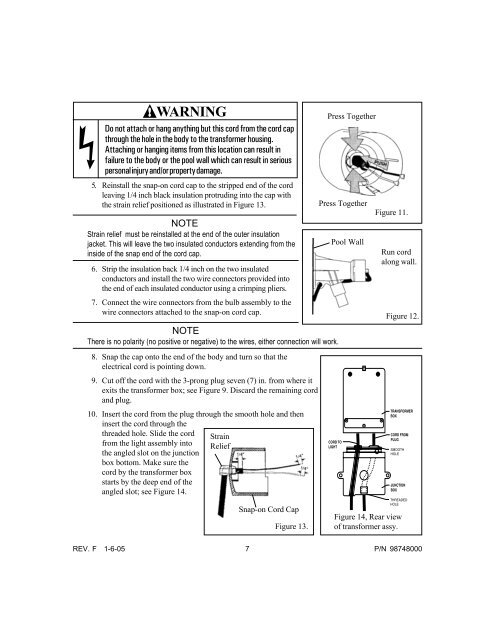
WARNING<br />
Do not attach or hang anything but this cord from the cord cap<br />
through the hole in the body to the trans<strong>for</strong>mer housing.<br />
Attaching or hanging items from this location can result in<br />
failure to the body or the pool wall which can result in serious<br />
personal injury <strong>and</strong>/or property damage.<br />
5. Reinstall the snap-on cord cap to the stripped end of the cord<br />
leaving 1/4 inch black insulation protruding into the cap with<br />
the strain relief positioned as illustrated in Figure 13.<br />
NOTE<br />
Strain relief must be reinstalled at the end of the outer insulation<br />
jacket. This will leave the two insulated conductors extending from the<br />
inside of the snap end of the cord cap.<br />
6. Strip the insulation back 1/4 inch on the two insulated<br />
conductors <strong>and</strong> install the two wire connectors provided into<br />
the end of each insulated conductor using a crimping pliers.<br />
7. Connect the wire connectors from the bulb assembly to the<br />
wire connectors attached to the snap-on cord cap.<br />
NOTE<br />
There is no polarity (no positive or negative) to the wires, either connection will work.<br />
8. Snap the cap onto the end of the body <strong>and</strong> turn so that the<br />
electrical cord is pointing down.<br />
9. Cut off the cord with the 3-prong plug seven (7) in. from where it<br />
exits the trans<strong>for</strong>mer box; see Figure 9. Discard the remaining cord<br />
<strong>and</strong> plug.<br />
10. Insert the cord from the plug through the smooth hole <strong>and</strong> then<br />
insert the cord through the<br />
threaded hole. Slide the cord<br />
from the light assembly into<br />
the angled slot on the junction<br />
box bottom. Make sure the<br />
cord by the trans<strong>for</strong>mer box<br />
starts by the deep end of the<br />
angled slot; see Figure 14.<br />
Strain<br />
Relief<br />
Press Together<br />
Press Together<br />
Pool Wall<br />
Figure 11.<br />
Run cord<br />
along wall.<br />
Figure 12.<br />
Snap-on Cord Cap<br />
Figure 13.<br />
Figure 14, Rear view<br />
of trans<strong>for</strong>mer assy.<br />
REV. F 1-6-05 7 P/N 98748000