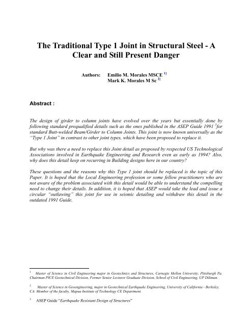
The Traditional Type 1 Joint in Structural Steel - A ... - Pgatech.com.ph
The Traditional Type 1 Joint in Structural Steel - A ... - Pgatech.com.ph
The Traditional Type 1 Joint in Structural Steel - A ... - Pgatech.com.ph

Create successful ePaper yourself
Turn your PDF publications into a flip-book with our unique Google optimized e-Paper software.
<strong>The</strong> <strong>Traditional</strong> <strong>Type</strong> 1 <strong>Jo<strong>in</strong>t</strong> <strong>in</strong> <strong>Structural</strong> <strong>Steel</strong> - A<br />
Clear and Still Present Danger<br />
Authors: Emilio M. Morales MSCE 1]<br />
Mark K. Morales M Sc 2]<br />
Abstract :<br />
<strong>The</strong> design of girder to column jo<strong>in</strong>ts have evolved over the years but essentially done by<br />
follow<strong>in</strong>g standard prequalified details such as the ones published <strong>in</strong> the ASEP Guide 1991 3 for<br />
standard Butt-welded Beam/Girder to Column <strong>Jo<strong>in</strong>t</strong>s. This jo<strong>in</strong>t is now known universally as the<br />
“<strong>Type</strong> 1 <strong>Jo<strong>in</strong>t</strong>” <strong>in</strong> contrast to other jo<strong>in</strong>t types, which have been proposed to replace it.<br />
But why was there a need to replace this <strong>Jo<strong>in</strong>t</strong> detail as proposed by respected US Technological<br />
Associations <strong>in</strong>volved <strong>in</strong> Earthquake Eng<strong>in</strong>eer<strong>in</strong>g and Research even as early as 1994? Also,<br />
why does this detail keep on recurr<strong>in</strong>g <strong>in</strong> Build<strong>in</strong>g designs here <strong>in</strong> our country?<br />
<strong>The</strong>se questions and the reasons why this <strong>Type</strong> 1 jo<strong>in</strong>t should be replaced is the topic of this<br />
Paper. It is hoped that the Local Eng<strong>in</strong>eer<strong>in</strong>g profession or some fellow practitioners who are<br />
not aware of the problem associated with this detail would be able to understand the <strong>com</strong>pell<strong>in</strong>g<br />
need to change their details. In addition, it is hoped that ASEP would take the lead and issue a<br />
circular “outlaw<strong>in</strong>g” this jo<strong>in</strong>t for use <strong>in</strong> seismic detail<strong>in</strong>g and withdraw this detail <strong>in</strong> the<br />
outdated 1991 Guide.<br />
1<br />
Master of Science <strong>in</strong> Civil Eng<strong>in</strong>eer<strong>in</strong>g major <strong>in</strong> Geotechnics and Structures, Carnegie Mellon University, Pittsburgh Pa.<br />
Chairman PICE Geotechnical Division, Former Senior Lecturer Graduate Division, School of Civil Eng<strong>in</strong>eer<strong>in</strong>g, UP Diliman.<br />
2<br />
Master of Science <strong>in</strong> Geoeng<strong>in</strong>eer<strong>in</strong>g, major <strong>in</strong> Geotechnical Earthquake Eng<strong>in</strong>eer<strong>in</strong>g, University of California - Berkeley,<br />
CA. Member of the faculty, Mapua Institute of Technology CE Department.<br />
3<br />
ASEP Guide “Earthquake Resistant Design of Structures”
THE TRADITIONAL TYPE 1 JOINT IN STRUCTURAL STEEL –<br />
A CLEAR AND STILL PRESENT DANGER<br />
1.0 Introduction<br />
As soon as the f<strong>in</strong>d<strong>in</strong>gs of the<br />
Northridge Earthquake of 1994 became<br />
<strong>com</strong>mon knowledge <strong>in</strong> the Eng<strong>in</strong>eer<strong>in</strong>g<br />
<strong>com</strong>munity both locally and abroad, serious<br />
questions have arose regard<strong>in</strong>g the highly<br />
critical vulnerability of the <strong>Traditional</strong> <strong>Type</strong><br />
1 or the Butt-welded Beam/Girder to<br />
Column <strong>Jo<strong>in</strong>t</strong> <strong>in</strong> structural <strong>Steel</strong><br />
construction. It was found out that<br />
significant failures occurred <strong>in</strong> localized<br />
regions of the jo<strong>in</strong>t and column flanges,<br />
which required very costly repairs. As a<br />
result, some build<strong>in</strong>gs <strong>in</strong> California that<br />
otherwise appeared safe (At least <strong>in</strong> external<br />
appearance), had to be razed because of the<br />
uneconomic cost of repairs entailed by<br />
damage susta<strong>in</strong>ed by this <strong>Type</strong> 1 jo<strong>in</strong>t.<br />
This <strong>Jo<strong>in</strong>t</strong> <strong>Type</strong> is illustrated below <strong>in</strong><br />
3D render<strong>in</strong>g taken from Ref 6] and shows<br />
the connection detail where the Beam or<br />
Girder Flanges and the web are butt-welded<br />
to the column Flange. <strong>The</strong> Column may or<br />
may not be re<strong>in</strong>forced with web stiffeners.<br />
research organizations such as the SAC<br />
Committee 4<br />
However, and surpris<strong>in</strong>gly as we have<br />
observed <strong>in</strong> the local Eng<strong>in</strong>eer<strong>in</strong>g<br />
<strong>com</strong>munity, some design houses were still<br />
very slow to adopt or have cont<strong>in</strong>ued the use<br />
of the highly vulnerable <strong>Traditional</strong> <strong>Type</strong> 1<br />
jo<strong>in</strong>t detail despite almost 10 years s<strong>in</strong>ce this<br />
jo<strong>in</strong>t was removed from the re<strong>com</strong>mended<br />
details.<br />
Why this poor state of affairs? Partially<br />
this is to be blamed on the lack of knowledge<br />
and <strong>in</strong>formation on developments <strong>in</strong> the<br />
structural eng<strong>in</strong>eer<strong>in</strong>g field due to lack of<br />
funds for keep<strong>in</strong>g abreast of the state-of<br />
practice and/or lack of <strong>in</strong>terest. Also, this<br />
could be partly because the ASEP 5] has not<br />
superseded the 1991 Guide which conta<strong>in</strong>ed<br />
this orig<strong>in</strong>ally “re<strong>com</strong>mended” but otherwise<br />
banned <strong>Traditional</strong> <strong>Type</strong> 1 jo<strong>in</strong>t detail.<br />
However, both these two situations are<br />
not acceptable excuses particularly nowadays<br />
because of the easy access to FREE technical<br />
<strong>in</strong>formation from the Internet where most of<br />
the materials <strong>in</strong> this Paper have been<br />
obta<strong>in</strong>ed.<br />
This problem, which prompted the<br />
writ<strong>in</strong>g of this paper, became glar<strong>in</strong>gly<br />
evident when our office was asked recently to<br />
do a value eng<strong>in</strong>eer<strong>in</strong>g study for a 5-Storey<br />
structural steel <strong>com</strong>mercial build<strong>in</strong>g, which<br />
was already <strong>in</strong> the bidd<strong>in</strong>g pipel<strong>in</strong>e.<br />
Aside from our f<strong>in</strong>d<strong>in</strong>gs that the build<strong>in</strong>g<br />
was over designed by as much as 30 to 40%<br />
Consultants who kept abreast of the<br />
State-of- Practice quickly abandoned this<br />
detail and adopted the Official<br />
re<strong>com</strong>mendations published by various<br />
4 Task Committee <strong>com</strong>posed of the <strong>Structural</strong><br />
Eng<strong>in</strong>eers Association of California (SEAOC), the<br />
Applied Technology Council (ATC) and the<br />
California Universities for Research <strong>in</strong> Earthquake<br />
Eng<strong>in</strong>eer<strong>in</strong>g (CUREE) ). Collectively known as the<br />
SAC <strong>Jo<strong>in</strong>t</strong> venture.<br />
5 Association of <strong>Structural</strong> Eng<strong>in</strong>eers of the<br />
Philipp<strong>in</strong>es<br />
Emilio M. Morales, MSCE and Mark K. Morales, M.Sc. page 2
THE TRADITIONAL TYPE 1 JOINT IN STRUCTURAL STEEL –<br />
A CLEAR AND STILL PRESENT DANGER<br />
for the primary structural fram<strong>in</strong>g system, <strong>The</strong> follow<strong>in</strong>g detail was lifted from the<br />
ironically, failure could still ensue despite the ASEP Guide 4]<br />
over design due to the highly vulnerable<br />
<strong>Traditional</strong> <strong>Type</strong> 1 jo<strong>in</strong>t detail provided <strong>in</strong> the<br />
plans. To <strong>com</strong>pound the problem, the<br />
build<strong>in</strong>g was long but narrow <strong>in</strong> plan and<br />
required a column free <strong>in</strong>terior. This resulted<br />
<strong>in</strong> dependence on only two column rows<br />
leav<strong>in</strong>g no alternative stress paths. Thus a<br />
dom<strong>in</strong>o type collapse is possible with a<br />
failure <strong>in</strong> one of the jo<strong>in</strong>ts as the girder spans Lifted from Ref 2 ASEP Guide<br />
Earthquake Resistant Design of<br />
are relatively large at 15 meters.<br />
Structures.<br />
1.1 <strong>The</strong> ASEP Guide “ Earthquake<br />
<strong>Type</strong> 1 <strong>Jo<strong>in</strong>t</strong> <strong>in</strong> ASEP Guide<br />
Resistant Design of Structures”<br />
1991 Edition 6]<br />
2.0 Historical Background<br />
<strong>The</strong> ASEP Guide “ Earthquake<br />
<strong>The</strong> Northridge earthquake resulted <strong>in</strong><br />
Resistant Design of Structures” 1991<br />
57 deaths, more than 5,000 <strong>in</strong>jured and $20<br />
Edition conta<strong>in</strong>ed <strong>in</strong> Chapter 4<br />
billion <strong>in</strong> property damages, mak<strong>in</strong>g it the<br />
“Re<strong>com</strong>mended <strong>Structural</strong> Detail<strong>in</strong>g<br />
costliest seismic disaster <strong>in</strong> U.S. history.<br />
Practices” the <strong>Traditional</strong> <strong>Type</strong> 1 jo<strong>in</strong>t detail<br />
Severe structural damage was seen <strong>in</strong> a wide<br />
as connection Detail 4.29 on page 182.<br />
variety of build<strong>in</strong>gs. <strong>The</strong> eng<strong>in</strong>eer<strong>in</strong>g<br />
<strong>com</strong>munity was specially surprised by the<br />
In addition, page 178 of the same Guide<br />
poor performance of the highly regarded and<br />
required a Column to Girder Strength Ratio<br />
widely used beam-to-column welded<br />
of 1.25. While this requirement could<br />
connections of <strong>Steel</strong> Moment Resist<strong>in</strong>g<br />
promote a “Weak Beam Strong Column”<br />
Frames (SMRF).<br />
(WBSC) approach espoused <strong>in</strong> later studies,<br />
this pre-Northridge Earthquake” provision<br />
After the Earthquake of January 17, 1994, a<br />
was not enough to prevent damage to this<br />
task <strong>com</strong>mittee was formed <strong>in</strong> the USA<br />
<strong>Type</strong> of <strong>Jo<strong>in</strong>t</strong>.<br />
consist<strong>in</strong>g of the <strong>Structural</strong> Eng<strong>in</strong>eers<br />
Association of California (SEAOC), the<br />
It should be noted that the ASEP Guide<br />
Applied Technology Council and the<br />
was published as the 1991 Edition. <strong>The</strong><br />
California Universities for Research <strong>in</strong><br />
Northridge Earthquake occurred <strong>in</strong> 1994 or<br />
Earthquake Eng<strong>in</strong>eer<strong>in</strong>g (CUREE)).<br />
3 years after this publication. Our recent<br />
Collectively known as the SAC <strong>Jo<strong>in</strong>t</strong><br />
7].<br />
tele<strong>ph</strong>one <strong>in</strong>quiry with the ASEP Secretariat<br />
venture Ref <strong>The</strong> SAC studied Post<br />
7]<br />
<strong>in</strong>dicated that this Edition has not been<br />
earthquake damage effects. A very<br />
superseded by later publications.<br />
disturb<strong>in</strong>g or even alarm<strong>in</strong>g consequence is<br />
the discovery of numerous damages <strong>in</strong> beam<br />
to column <strong>Jo<strong>in</strong>t</strong> connections, which were<br />
based on what is now known as the<br />
6 ASEP Guide “Earthquake Resistant Design of “<strong>Traditional</strong> <strong>Type</strong> 1 Connection” for<br />
Structures.” 1991 Edition<br />
Moment framed jo<strong>in</strong>ts.<br />
7 Tele<strong>ph</strong>one Inquiry June 10, 2005<br />
Emilio M. Morales, MSCE and Mark K. Morales, M.Sc. page 3
THE TRADITIONAL TYPE 1 JOINT IN STRUCTURAL STEEL –<br />
A CLEAR AND STILL PRESENT DANGER<br />
Excerpts from the report are collected<br />
here<strong>in</strong> to shed more light on the criticality of<br />
this type of jo<strong>in</strong>t.<br />
“Prevail<strong>in</strong>g construction design codes<br />
take <strong>in</strong>to account a strong <strong>in</strong>elastic<br />
behavior by the steel structure when<br />
exposed to earthquake ground motion.<br />
This is why ductile elements and<br />
connections are used <strong>in</strong> the SMRF.<br />
Based on research dat<strong>in</strong>g back to the<br />
1960’s and previous earthquake<br />
experiences the steel frame with moment<br />
resist<strong>in</strong>g connections has been<br />
considered the most reliable seismic<br />
resistance design for low and high-rise<br />
build<strong>in</strong>gs. <strong>The</strong> <strong>com</strong>mon usage of welded<br />
steel moment resist<strong>in</strong>g frame is also a<br />
consequence of its versatility, economy,<br />
and its supposed high plastic<br />
deformation capacity.<br />
practice. It was proved that those welded<br />
SMRF connections did not fulfill the<br />
design <strong>in</strong>tent of provid<strong>in</strong>g reliability and<br />
safety. Research was <strong>in</strong>itiated to improve<br />
these connections.<br />
(“<strong>The</strong> Northridge Earthquake and Welded<br />
SMRF “) Anon 3].<br />
3.0 Girder to Column Moment<br />
<strong>Jo<strong>in</strong>t</strong> Details<br />
3.1 <strong>Traditional</strong> Girder Column <strong>Jo<strong>in</strong>t</strong><br />
Detail<br />
<strong>The</strong> Figures below, taken from Ref 6]<br />
show the various <strong>com</strong>ponents of the typical<br />
“<strong>Type</strong> 1” Pre Northridge Earthquake<br />
<strong>Traditional</strong> <strong>Type</strong> 1 <strong>Jo<strong>in</strong>t</strong> connection detail.<br />
In just 15 seconds, the Northridge<br />
Earthquake <strong>in</strong>validated historic design<br />
approaches and proved wrong the<br />
theory of <strong>in</strong>tegral ductile response of the<br />
welded SMRF. In more than 250<br />
build<strong>in</strong>gs, brittle fractures were<br />
discovered <strong>in</strong> the welded beam-tocolumn<br />
jo<strong>in</strong>ts. Fortunately not a s<strong>in</strong>gle<br />
build<strong>in</strong>g collapsed and no death or<br />
<strong>in</strong>jury occurred due to the unexpected<br />
mode of failure. <strong>The</strong> cracks were<br />
observed through the beam-to-column<br />
welds and/or through the base metal of<br />
the beam or column flanges. <strong>The</strong>se<br />
cracks resulted <strong>in</strong> a loss of seismic<br />
moment resistance <strong>in</strong> the damaged<br />
connections; however, the connections<br />
still transferred gravity loads which may<br />
expla<strong>in</strong> why there were no total<br />
collapses triggered by the brittle failure<br />
of welded jo<strong>in</strong>ts.”<br />
<strong>The</strong> Northridge earthquake caused an<br />
unexpected brittle failure on welded<br />
SMRF constructed conform<strong>in</strong>g to<br />
modern build<strong>in</strong>g codes and standards of<br />
<strong>The</strong> forego<strong>in</strong>g is the same detail<br />
<strong>in</strong>corporated <strong>in</strong> the ASEP Guide<br />
“Earthquake Resistant Design of Structures<br />
1991 Ed” unfortunately; this guide has not<br />
been replaced nor superseded to reflect the<br />
current State of knowledge regard<strong>in</strong>g the<br />
problems associated with this connection<br />
detail <strong>in</strong> the light of the Northridge<br />
Earthquake experience.<br />
<strong>The</strong> failures are primarily attributed to a<br />
fundamental flaw <strong>in</strong> the standard codeprescribed<br />
welded-flange bolted-web<br />
Emilio M. Morales, MSCE and Mark K. Morales, M.Sc. page 4
THE TRADITIONAL TYPE 1 JOINT IN STRUCTURAL STEEL –<br />
A CLEAR AND STILL PRESENT DANGER<br />
connection and the extreme ground motion<br />
at the site. 8]<br />
As would be evident <strong>in</strong> this report, this<br />
type of detail would no longer be acceptable<br />
based on current state of practice due to the<br />
<strong>in</strong>herent lack of ductility and propensity for<br />
localized failure <strong>in</strong> the jo<strong>in</strong>t panel based on<br />
numerous recorded failures of this <strong>Type</strong> of<br />
<strong>Jo<strong>in</strong>t</strong>.<br />
Below is a Detail from a draw<strong>in</strong>g for the<br />
5 Storey Commercial build<strong>in</strong>g, which was<br />
the subject of the Value Eng<strong>in</strong>eer<strong>in</strong>g we<br />
conducted:<br />
GIRDER<br />
GIRDER (WHERE<br />
OCCURS)<br />
COLUMN<br />
2. Connection plates (“Stiffener”) at the<br />
level of the top and bottom flanges<br />
were <strong>in</strong>corporated with<strong>in</strong> the jo<strong>in</strong>t<br />
panel as stiffener plates.<br />
3. <strong>The</strong> girder web is connected to the<br />
column by means of connector plates<br />
butt welded to the column us<strong>in</strong>g a Vee<br />
weld.<br />
<strong>The</strong> forego<strong>in</strong>g figure shows that the jo<strong>in</strong>t<br />
connection details are similar to or identical to<br />
jo<strong>in</strong>t connection details <strong>in</strong> use prior to the<br />
Northridge Earthquake, which consists<br />
essentially of Girders be<strong>in</strong>g framed <strong>in</strong>to<br />
columns by full weld<strong>in</strong>g of the Girder Flanges<br />
to the correspond<strong>in</strong>g column Flanges or webs<br />
by butt or groove welds. <strong>The</strong>se welds were<br />
very much <strong>in</strong> use pre 1994 until detailed post<br />
Northridge Earthquake damage evaluation<br />
<strong>in</strong>dicated that someth<strong>in</strong>g was terribly wrong<br />
with these jo<strong>in</strong>ts.<br />
CONNECTOR PLATE<br />
A1<br />
A2<br />
01SF501<br />
DETAIL<br />
NTS<br />
GIRDER \ CANTILEVER<br />
GIRDER (WHERE<br />
OCCURS)<br />
CONNECTORPLATE<br />
Based on the details as shown above, taken<br />
from a scan of the draw<strong>in</strong>gs, the follow<strong>in</strong>g<br />
are ma<strong>in</strong> features of the <strong>Jo<strong>in</strong>t</strong> detail:<br />
1. A plug weld is used to weld the<br />
Girder flanges supported by a<br />
back<strong>in</strong>g bar or spacer directly to the<br />
column flanges.<br />
3.2 <strong>Type</strong> 1 <strong>Jo<strong>in</strong>t</strong> Failure Mechanism<br />
Simply stated, the problem with the<br />
traditional <strong>Type</strong> 1 Connection is the lack of<br />
Ductility <strong>in</strong> the Panel <strong>Jo<strong>in</strong>t</strong> connection details<br />
lead<strong>in</strong>g to brittle fractures. However, the crack<br />
<strong>in</strong>itiation and propagation mechanism is not as<br />
simple. In all cases where the <strong>Type</strong> 1 jo<strong>in</strong>t was<br />
exam<strong>in</strong>ed, failure was at the region of the<br />
connection between the top and/or bottom<br />
Girder flange/s and the column.<br />
Failure was <strong>in</strong>itiated <strong>in</strong> all <strong>in</strong>stances by the<br />
<strong>in</strong><strong>com</strong>plete fusion flaw as provided by the<br />
back<strong>in</strong>g bar and its gap to the column flange.<br />
This constitutes a pseudo crack, which<br />
be<strong>com</strong>es a stress raiser dur<strong>in</strong>g cyclic load<strong>in</strong>g<br />
lead<strong>in</strong>g to crack <strong>in</strong>itiation.<br />
<strong>The</strong> open notch tip of the weldment where<br />
the back<strong>in</strong>g bar is placed simulates a crack <strong>in</strong><br />
8 David P. O’Sullivan et al “Repairs to Mid-Rise itself. Dur<strong>in</strong>g cyclic dynamic load<strong>in</strong>g, the<br />
<strong>Steel</strong> Frame Damaged <strong>in</strong> Northridge Earthquake” crack propagates <strong>in</strong>to the weld metal <strong>in</strong>to the<br />
ASCE Journal of Performance of Constructed<br />
Heat affected zones (HAZ) and unaffected<br />
Facilities, Vol. 12, No. 4, November 1998, pp. 213-<br />
zones.<br />
220<br />
Emilio M. Morales, MSCE and Mark K. Morales, M.Sc. page 5
THE TRADITIONAL TYPE 1 JOINT IN STRUCTURAL STEEL –<br />
A CLEAR AND STILL PRESENT DANGER<br />
It would be necessary to shift any failure<br />
to the connect<strong>in</strong>g Girder (or Beam) away from<br />
the <strong>Jo<strong>in</strong>t</strong>. This would ensure that plastic<br />
h<strong>in</strong>g<strong>in</strong>g would occur at the Girder to allow<br />
flexural yield<strong>in</strong>g rather than a brittle type of<br />
Failure. This is the basis for the<br />
re<strong>com</strong>mendation Ref 9] to have a “weak beam<br />
strong column concept” (WBSC) <strong>in</strong> order to<br />
assure that the failure is not brittle. Provid<strong>in</strong>g<br />
a weaker beam (relative to column strength)<br />
assures that the failure would be that of plastic<br />
h<strong>in</strong>g<strong>in</strong>g of the beam, which ensures the<br />
extended ductility of the system. Formation of<br />
plastic h<strong>in</strong>ges <strong>in</strong> the beam promotes a “beam<br />
sway mode” Failure mechanism, which is<br />
preferred over “column h<strong>in</strong>g<strong>in</strong>g”, which could<br />
result <strong>in</strong> more catastro<strong>ph</strong>ic collapse modes.<br />
Damage to Column very Severe<br />
Researchers have found that the stresses<br />
<strong>in</strong>duced <strong>in</strong> the process although highly<br />
localized, are at least one order of magnitude<br />
higher than the stresses predicted by elastic<br />
analyses. <strong>The</strong>se highly localized overstresses<br />
are concentrated at the Girder bottom flange<br />
connection with<strong>in</strong> the critical jo<strong>in</strong>t panel<br />
connection.<br />
This is <strong>com</strong>pounded by the problem that<br />
this portion of the jo<strong>in</strong>t is the least accessible<br />
under field weld<strong>in</strong>g conditions thus; the<br />
quality of workmanship be<strong>com</strong>es an issue.<br />
This is highly undesirable, as we would not<br />
want the failure to <strong>in</strong>itiate at the column or at<br />
the critical jo<strong>in</strong>t Panel connection as both<br />
would exhibit brittle failure modes.<br />
<strong>The</strong> AISC “Seismic Provisions for<br />
<strong>Structural</strong> <strong>Steel</strong> Build<strong>in</strong>gs of 1997” Ref 9] for<br />
<strong>in</strong>termediate and special moment frames has<br />
adopted the position that:<br />
“For Fully Restra<strong>in</strong>ed Connections,<br />
yield<strong>in</strong>g must take place <strong>in</strong> the members<br />
of the frame (plastic h<strong>in</strong>ge <strong>in</strong> beam,<br />
panel zone, etc.) and not <strong>in</strong> the<br />
connections.<br />
However, s<strong>in</strong>ce yield<strong>in</strong>g <strong>in</strong> the column is<br />
the least desirable result, the design<br />
eng<strong>in</strong>eer should consider design<strong>in</strong>g the<br />
system such that flexural yield<strong>in</strong>g occurs<br />
<strong>in</strong> the beam. For FR connections that are<br />
part of ord<strong>in</strong>ary moment frames, the<br />
connect<strong>in</strong>g elements may yield as long as<br />
Emilio M. Morales, MSCE and Mark K. Morales, M.Sc. page 6
THE TRADITIONAL TYPE 1 JOINT IN STRUCTURAL STEEL –<br />
A CLEAR AND STILL PRESENT DANGER<br />
0.01 radians of plastic rotation can be<br />
provided by the system”<br />
A study of the result<strong>in</strong>g stresses and stra<strong>in</strong>s<br />
under repeated cyclic load<strong>in</strong>g of a <strong>Type</strong> 1<br />
<strong>Jo<strong>in</strong>t</strong> was made as part of the study reported<br />
<strong>in</strong> Ref 6] (See Appendix). <strong>The</strong> color contour<br />
<strong>in</strong>dicate the severe stress and stra<strong>in</strong><br />
concentrations at the Girder flange to<br />
column Flange <strong>in</strong>tersections.<br />
<strong>The</strong> study concluded that:<br />
“<strong>The</strong> traditional (<strong>Type</strong> 1) moment<br />
connection experienced high-order bidirectional<br />
localized plastic stra<strong>in</strong> at the<br />
weld root at critical junctures between<br />
the girder and column, which is one of<br />
the causes of premature brittle fracture.<br />
<strong>The</strong> stra<strong>in</strong> patterns shown <strong>in</strong> Figure 16<br />
clearly <strong>in</strong>dicate the propensity for this<br />
<strong>ph</strong>enomenon. <strong>The</strong> stra<strong>in</strong> gradient is<br />
particularly pronounced at the mid<br />
plane of the girder near the weld and<br />
weld access hole.”<br />
<strong>The</strong> study further revealed that:<br />
“Yield stress near the weld access hole<br />
and flange weld is exceeded early on <strong>in</strong><br />
the load<strong>in</strong>g. <strong>The</strong> stra<strong>in</strong> plots near the<br />
weld access hole and flange weld show<br />
the stress reversal <strong>in</strong> the free edge of the<br />
girder flange, which is typical for<br />
traditional moment connections and a<br />
causative factor <strong>in</strong> fractures <strong>in</strong>itiated<br />
from this region of the flange weld. This<br />
can potentially lead to fractures either <strong>in</strong><br />
the flange or, far more critically from<br />
the progressive failure perspective, <strong>in</strong><br />
the column flange. It is primarily this<br />
mode of failure that effected moment<br />
connection damage <strong>in</strong> the Northridge<br />
earthquake.“<br />
<strong>Type</strong> 1 Connection Show<strong>in</strong>g Von Mises Stress<br />
Contours<br />
3.3 Post Northridge Earthquake<br />
Damage Assessment Studies<br />
From these studies it was clearly evident<br />
that the “<strong>Traditional</strong>” <strong>Type</strong> 1 pre Northridge<br />
connection details normally used and<br />
espoused by various authorities of that time<br />
have failed miserably and at jo<strong>in</strong>t locations<br />
that are not necessarily the worst stressed<br />
member based on post damage reanalysis of<br />
the build<strong>in</strong>gs.<br />
In the research done by Mah<strong>in</strong> S. Ref 3] ,<br />
from the University of California at<br />
Berkeley, we quote his f<strong>in</strong>d<strong>in</strong>gs:<br />
“Comparisons of damage survey<br />
data with results of elastic analyses of<br />
the build<strong>in</strong>gs (us<strong>in</strong>g recorded and<br />
simulated Northridge earthquake<br />
records developed for the build<strong>in</strong>g sites<br />
[5]) show relatively poor correlation.<br />
Analyses suggest that the most<br />
heavily stressed jo<strong>in</strong>ts are most likely to<br />
be damaged; however, the precise<br />
location and severity of damage was not<br />
Emilio M. Morales, MSCE and Mark K. Morales, M.Sc. page 7
THE TRADITIONAL TYPE 1 JOINT IN STRUCTURAL STEEL –<br />
A CLEAR AND STILL PRESENT DANGER<br />
reliably predicted by conventional<br />
elastic dynamic analyses. <strong>The</strong> 60% most<br />
highly stressed connections <strong>in</strong> a<br />
structure (relative to their capacities)<br />
have roughly equal chance of be<strong>in</strong>g<br />
damaged. Areas of low <strong>com</strong>puted stress<br />
were also subject to damage. Thus,<br />
analysis may not be a good way of<br />
assess<strong>in</strong>g the particular jo<strong>in</strong>ts to <strong>in</strong>spect,<br />
though it may <strong>in</strong>dicate floors that should<br />
be <strong>in</strong>spected. <strong>The</strong> reasons for differences<br />
between observed and <strong>com</strong>puted<br />
behavior <strong>in</strong>clude the effects of <strong>in</strong>itial<br />
defects and poor workmanship, and the<br />
limitations of current analytical methods<br />
and models. For <strong>in</strong>stance, <strong>in</strong>clusion of<br />
slabs and panel zones had an important<br />
effect.<br />
Most design calculations are based<br />
on an assumption that plane sections<br />
rema<strong>in</strong> plane dur<strong>in</strong>g deformation.<br />
However, review of experimental data<br />
and results of f<strong>in</strong>ite element analyses<br />
suggest that this is far from true, with<br />
high local bend<strong>in</strong>g and shear<br />
deformations be<strong>in</strong>g <strong>in</strong>duced <strong>in</strong> beam and<br />
column flanges. This is especially<br />
pronounced when plastic shear<strong>in</strong>g<br />
deformations occur <strong>in</strong> the panel zone.<br />
Results demonstrated that these panel<br />
zone deformations were often very large.<br />
In such cases, the distribution of shear<br />
stress over the depth of the beam's web<br />
is not uniform, often concentrat<strong>in</strong>g the<br />
majority of the shear force <strong>in</strong> the highly<br />
stressed beam flanges. Compound<strong>in</strong>g<br />
this situation is the fact that actual<br />
material properties are not uniform, and<br />
vary randomly from member to member<br />
and systematically with load<strong>in</strong>g<br />
direction, section size, and weld<strong>in</strong>g<br />
procedures. Normal member-to-member<br />
variation of material properties may<br />
result <strong>in</strong> members stronger than the<br />
connect<strong>in</strong>g weld, or a column that is<br />
weaker than the supported beam. As a<br />
result, the jo<strong>in</strong>t may have negligible<br />
<strong>in</strong>elastic deformation capacity,<br />
regardless of workmanship.” (Mah<strong>in</strong>)<br />
Ref 3]<br />
In just 15 seconds, the Northridge<br />
Earthquake <strong>in</strong>validated historic design<br />
approaches and proved wrong the<br />
theory of <strong>in</strong>tegral ductile re<br />
<strong>The</strong> Northridge earthquake caused<br />
an unexpected brittle failure on welded<br />
SMRF constructed conform<strong>in</strong>g to<br />
modern build<strong>in</strong>g codes and standards of<br />
practice. It was proved that those welded<br />
SMRF connections did not fulfill the<br />
design <strong>in</strong>tent of provid<strong>in</strong>g reliability and<br />
safety. Research was <strong>in</strong>itiated to improve<br />
these connections.<br />
(“<strong>The</strong> Northridge Earthquake and Welded<br />
SMRF “) Anon 3].<br />
3.4 <strong>The</strong> Northridge Earthquake and<br />
Damage to Beam Column<br />
Connections<br />
<strong>The</strong> figure below shows the various<br />
types of damage to <strong>Jo<strong>in</strong>t</strong> Panel Connections<br />
susta<strong>in</strong>ed dur<strong>in</strong>g the Northridge Earthquake<br />
susta<strong>in</strong>ed by the <strong>Traditional</strong> <strong>Type</strong> 1 <strong>Jo<strong>in</strong>t</strong><br />
Detail after Youssef. (<strong>The</strong> numbered arrows<br />
po<strong>in</strong>t to the Cracks)<br />
Emilio M. Morales, MSCE and Mark K. Morales, M.Sc. page 8
THE TRADITIONAL TYPE 1 JOINT IN STRUCTURAL STEEL –<br />
A CLEAR AND STILL PRESENT DANGER<br />
<strong>in</strong> addition to other proprietary and nonproprietary<br />
jo<strong>in</strong>t details.<br />
It is suggested that Eng<strong>in</strong>eers who have not<br />
done so yet, consider abandon<strong>in</strong>g the <strong>Type</strong> 1<br />
<strong>Jo<strong>in</strong>t</strong> <strong>in</strong> favor of the <strong>Type</strong> 3 <strong>Jo<strong>in</strong>t</strong> <strong>in</strong> order to<br />
correct the potential problems associated<br />
with the former.<br />
<strong>The</strong>re are now available prequalified<br />
jo<strong>in</strong>t details, which could replace the <strong>Type</strong> 1<br />
<strong>Jo<strong>in</strong>t</strong>. Tests conducted on these alternative<br />
details to replace the <strong>Type</strong> 1 connection<br />
have been made and are available <strong>in</strong> current<br />
literature Bjorhovde R. Ref 5] and Houghton<br />
ref 6] .<br />
Several details have be<strong>com</strong>e prequalified<br />
as replacement for <strong>Type</strong> 1 <strong>Jo<strong>in</strong>t</strong>s <strong>in</strong> new<br />
construction.<br />
NOTE:<br />
Numbered bubbles po<strong>in</strong>t to cracks<br />
<strong>The</strong> primary objective is to promote the<br />
“weak beam strong column” (WBSC)<br />
concept. This is to ensure that <strong>in</strong>itial<br />
yield<strong>in</strong>g will <strong>in</strong>itiate at the girder a distance<br />
from the <strong>Jo<strong>in</strong>t</strong> and not at the more<br />
vulnerable column panel where failure<br />
would be <strong>in</strong> the brittle rather than ductile<br />
mode.<br />
Bjorhovde R. Ref 5] made tests on such<br />
prototype jo<strong>in</strong>ts and of these, the so-called<br />
“<strong>Type</strong> 3 <strong>Jo<strong>in</strong>t</strong>” performed very well.<br />
4.0 Conclusions<br />
Researchers and research establishments<br />
<strong>in</strong> the United States have evaluated several<br />
candidate replacement <strong>Jo<strong>in</strong>t</strong> details. Fullscale<br />
load tests under cyclic load<strong>in</strong>g were<br />
also conducted to determ<strong>in</strong>e the response of<br />
the various jo<strong>in</strong>t details to cyclic load<strong>in</strong>g.<br />
For the <strong>Type</strong> 3 connections it was<br />
decided to place the cont<strong>in</strong>uity plates with<br />
the outside edge <strong>in</strong> l<strong>in</strong>e with the beam flange<br />
to cover plate <strong>in</strong>terface. Figure 4 shows the<br />
details of the Revised <strong>Type</strong> 3 connection.<br />
Bjorhovde R. Ref 5]<br />
4.1 Cover Plate Connections<br />
As a result, pre tested details have been<br />
evolved and <strong>in</strong>cluded <strong>in</strong> the<br />
re<strong>com</strong>mendations. Of this, the <strong>Type</strong> 3 jo<strong>in</strong>t<br />
shown subsequently has been re<strong>com</strong>mended<br />
Thus, it can be seen that the <strong>in</strong>troduction<br />
of cover plates, which has the effect of<br />
mak<strong>in</strong>g the jo<strong>in</strong>t strong where it is<br />
coverplated, transfers the stresses to the<br />
weaker beam section beyond the jo<strong>in</strong>t<br />
Emilio M. Morales, MSCE and Mark K. Morales, M.Sc. page 9
THE TRADITIONAL TYPE 1 JOINT IN STRUCTURAL STEEL –<br />
A CLEAR AND STILL PRESENT DANGER<br />
coverplate <strong>in</strong>itiat<strong>in</strong>g a more ductile failure<br />
mode.<br />
4.2 Conclusions <strong>in</strong> the Study by<br />
Bjorhovde Ref 5]<br />
“<strong>The</strong> tests of the “<strong>Type</strong> 3” connections<br />
demonstrated excellent plastic rotation and<br />
energy absorption capacities. It was also<br />
found that although cracks developed and<br />
eventually propagated through the column<br />
material, the propagation was slow and<br />
stable, with numerous crack arrests dur<strong>in</strong>g<br />
the test<strong>in</strong>g. Such was also the case for the<br />
cracks that propagated <strong>in</strong>to the column k-<br />
area, demonstrat<strong>in</strong>g that a crack <strong>in</strong> this<br />
region will propagate <strong>in</strong> stable fashion,<br />
given appropriate connection details and<br />
fracture paths. Further, these connections<br />
used th<strong>in</strong>ner cover plates and fillet welded<br />
and repositioned cont<strong>in</strong>uity plates. F<strong>in</strong>ally,<br />
the cropp<strong>in</strong>g of the 413 cont<strong>in</strong>uity plates is<br />
important, to the effect that the ends of the<br />
welds need to be kept away from the k-area,<br />
but this observation applies to all k<strong>in</strong>ds of<br />
welds and connections. In brief, fabrication<br />
and construction economies will be obta<strong>in</strong>ed<br />
with the Revised <strong>Type</strong> 3 connection.”<br />
Bjorhovde<br />
Alternative <strong>Jo<strong>in</strong>t</strong> Systems to Replace the<br />
<strong>Type</strong> 1 <strong>Jo<strong>in</strong>t</strong>.<br />
4.3 Re<strong>com</strong>mendations of the SAC<br />
Panel<br />
<strong>The</strong> SAC <strong>Jo<strong>in</strong>t</strong> Committee Ref 7] have<br />
issued re<strong>com</strong>mendations for Post Northridge<br />
Earthquake Build<strong>in</strong>g Construction conta<strong>in</strong>ed<br />
<strong>in</strong> “Interim Guidel<strong>in</strong>es: Evaluation, Repair,<br />
Modification and Design of <strong>Steel</strong> Moment<br />
Frames 3] “<br />
“<strong>The</strong> build<strong>in</strong>g code provisions for<br />
earthquake resistive design of Special<br />
Moment-Resist<strong>in</strong>g Frames (SMRFs) assume<br />
that these structures are extremely ductile<br />
and therefore are capable of large plastic<br />
rotations at, or near to, their beam-column<br />
connections. Based on limited research, and<br />
observations of damage experienced <strong>in</strong> the<br />
Northridge Earthquake, it appears that<br />
conventionally designed connection<br />
assemblies configured such that plastic<br />
deformation concentrates at the beamcolumn<br />
connection(referr<strong>in</strong>g to <strong>Type</strong> 1<br />
<strong>Jo<strong>in</strong>t</strong>s) are not capable of reliably<br />
withstand<strong>in</strong>g large plastic rotation<br />
demands. <strong>The</strong> reliability appears to<br />
decrease as the size of the connected<br />
member’s <strong>in</strong>creases. Other factors affect<strong>in</strong>g<br />
Emilio M. Morales, MSCE and Mark K. Morales, M.Sc. page 10
THE TRADITIONAL TYPE 1 JOINT IN STRUCTURAL STEEL –<br />
A CLEAR AND STILL PRESENT DANGER<br />
this reliability appear to <strong>in</strong>clude the<br />
quality of workmanship, jo<strong>in</strong>t detail<strong>in</strong>g,<br />
and toughness of the base and weld<br />
metals, relative strengths of the<br />
connection elements, and the <strong>com</strong>b<strong>in</strong>ed<br />
stresses present on these elements.<br />
Unfortunately, the quantitative<br />
relationship between these factors and<br />
connection reliability is not well def<strong>in</strong>ed<br />
at this time. In order to atta<strong>in</strong> frames<br />
that can reliably perform <strong>in</strong> a ductile<br />
manner, these Interim Guidel<strong>in</strong>es<br />
re<strong>com</strong>mend that SMRF connections be<br />
configured with sufficient strength so<br />
that plastic h<strong>in</strong>ges occur with<strong>in</strong> the beam<br />
span and away from the face of the<br />
column. All elements of the frame, and<br />
the connection itself, should be designed<br />
with adequate strength to develop these<br />
plastic h<strong>in</strong>ges. <strong>The</strong> result<strong>in</strong>g connection<br />
assemblies are somewhat <strong>com</strong>plex and<br />
the factors limit<strong>in</strong>g their behavior not<br />
always evident. <strong>The</strong>refore, qualification<br />
of connection designs through prototype<br />
test<strong>in</strong>g, or by reference to tests of similar<br />
connection configurations is<br />
re<strong>com</strong>mended.<br />
<strong>The</strong>se procedures should also be<br />
applied to the design of Ord<strong>in</strong>ary<br />
Moment-Resist<strong>in</strong>g Frames (OMRFs)<br />
located <strong>in</strong> zones of higher seismicity, or<br />
for which highly reliable earthquake<br />
performance is desired, unless it can be<br />
demonstrated that the connections can<br />
resist the actual demands from a design<br />
earthquake and rema<strong>in</strong> elastic. Interim<br />
Guidel<strong>in</strong>es for determ<strong>in</strong><strong>in</strong>g if a design<br />
meets this condition are provided. Light,<br />
s<strong>in</strong>gle-story, frame structures, the design<br />
of which is predom<strong>in</strong>ated by w<strong>in</strong>d loads,<br />
have performed well <strong>in</strong> past earthquakes<br />
and may cont<strong>in</strong>ue to be designed us<strong>in</strong>g<br />
conventional approaches, regardless of<br />
the seismic zone they are located <strong>in</strong>.<br />
Materials and workmanship are critical<br />
to frame behavior and careful<br />
specification and control of these factors<br />
is essential.<br />
Other jo<strong>in</strong>t details such as the<br />
<strong>in</strong>tentionally weakened beam with holes <strong>in</strong><br />
the web, and the Reduced Beam Section<br />
(RBS), “<strong>The</strong> Dog Bone” and proprietary<br />
technologies such as the “SidePlate “<br />
represent the other end of the spectrum.<br />
Houghton ref 6]<br />
<strong>The</strong> RBS or “Reduced Beam Section”<br />
also known as the “Dog Bone” because of its<br />
shape <strong>in</strong>troduces a weaken<strong>in</strong>g at the Beam<br />
or girder to allow it to fail <strong>in</strong> ductile mode<br />
ahead of the column.<br />
<strong>The</strong> “SidePlate “ is a patented<br />
proprietary technology. <strong>The</strong> <strong>in</strong>tention is to<br />
strengthen the Panel <strong>Jo<strong>in</strong>t</strong> with “SidePlate<br />
“ for the purpose of strengthen<strong>in</strong>g the jo<strong>in</strong>t<br />
and the column at the critical panel po<strong>in</strong>t.<br />
Tests have shown that even with the<br />
failure of one column such as <strong>in</strong> a bomb<br />
blast, the Build<strong>in</strong>g will not collapse. Thus,<br />
this patented jo<strong>in</strong>t is now be<strong>in</strong>g used <strong>in</strong><br />
construction of new US Federal Build<strong>in</strong>gs.<br />
Emilio M. Morales, MSCE and Mark K. Morales, M.Sc. page 11
THE TRADITIONAL TYPE 1 JOINT IN STRUCTURAL STEEL –<br />
A CLEAR AND STILL PRESENT DANGER<br />
If dead loads are not very significant,<br />
then the plastic h<strong>in</strong>ges can be <strong>in</strong>duced at<br />
D/3 from the end of the re<strong>in</strong>forced<br />
section. However, if gravity loads are<br />
significant then a plastic design and<br />
analysis should be undertaken to<br />
determ<strong>in</strong>e the actual location of plastic<br />
h<strong>in</strong>g<strong>in</strong>g.<br />
5.0 Closure<br />
<strong>The</strong> SAC <strong>Jo<strong>in</strong>t</strong> Committee also<br />
evaluated several other details one of which<br />
is the <strong>in</strong>duced Plastic H<strong>in</strong>ge at the web a<br />
distance from the stiffened Girder Column<br />
jo<strong>in</strong>t as shown below SAC <strong>Jo<strong>in</strong>t</strong> Committee<br />
ref 7] :<br />
It is evident from the forego<strong>in</strong>g that the<br />
<strong>Traditional</strong> <strong>Type</strong> 1 <strong>Jo<strong>in</strong>t</strong> Detail should not<br />
be used <strong>in</strong> <strong>Structural</strong> Details anymore and<br />
that there is a need to update, supersede,<br />
amend or resc<strong>in</strong>d the details given <strong>in</strong> the<br />
ASEP Guide of 1991 perta<strong>in</strong><strong>in</strong>g to this jo<strong>in</strong>t<br />
detail.<br />
For Questions or Queries:<br />
emmorales02@yahoo.<strong>com</strong><br />
Website:<br />
www.pgatech.<strong>com</strong>.<strong>ph</strong><br />
Emilio M. Morales, MSCE and Mark K. Morales, M.Sc. page 12
THE TRADITIONAL TYPE 1 JOINT IN STRUCTURAL STEEL –<br />
A CLEAR AND STILL PRESENT DANGER<br />
Table of references<br />
1. Task <strong>com</strong>mittee report SAC <strong>Jo<strong>in</strong>t</strong> venture ““Interim Guidel<strong>in</strong>es:<br />
Evaluation, Repair, Modification and Design of <strong>Steel</strong> Moment<br />
Frames”<br />
2. ASEP Guide “Earthquake Resistant Design of Structures” 1991<br />
Edition<br />
3. Ste<strong>ph</strong>en A. Mah<strong>in</strong>. “Lessons from <strong>Steel</strong> Build<strong>in</strong>gs Damaged<br />
by the Northridge Earthquake”. Department of Civil and<br />
Environmental Eng<strong>in</strong>eer<strong>in</strong>g, University of California, Berkeley.<br />
4. National Science Foundation- Failure Analysis of Welded <strong>Steel</strong><br />
Moment Frames Damaged <strong>in</strong> the Northridge Earthquake NISTIR<br />
5944<br />
5. Bjorhovde R. “Influence of Column Straighten<strong>in</strong>g Protocol on<br />
Connection Performance”. <strong>The</strong> Bjorhovde Group, Tucson,<br />
Arizona, U S A<br />
6. Houghton D. et al “Post 9-11 Multi-Hazard Mitigation <strong>in</strong> <strong>Steel</strong><br />
Frame Structures as a Function of Connection Geometry”.<br />
71st Annual Convention of the <strong>Structural</strong> Eng<strong>in</strong>eers Association<br />
of California, Santa Barbara, California. September 26-28, 2002<br />
7. SAC <strong>Jo<strong>in</strong>t</strong> Committee Interim Guidel<strong>in</strong>es: Evaluation, Repair,<br />
Modification and Design of <strong>Steel</strong> Moment Frames”.<br />
8. Federal Emergency Management Agency (2000). FEMA 350<br />
“Re<strong>com</strong>mended Seismic Design Criteria for New <strong>Steel</strong><br />
Moment-Frame Build<strong>in</strong>gs”.<br />
9. American Institute of <strong>Steel</strong> Construction, Inc. (1997). “Seismic<br />
Provisions for <strong>Structural</strong> <strong>Steel</strong> Build<strong>in</strong>gs”.<br />
10. Bruneau, M. and Uang, C-M (1998). “Ductile Design of<br />
Structures”, McGraw-Hill, New York, New York.<br />
Emilio M. Morales, MSCE and Mark K. Morales, M.Sc. page 13