You also want an ePaper? Increase the reach of your titles
YUMPU automatically turns print PDFs into web optimized ePapers that Google loves.
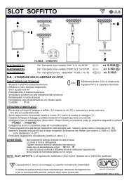
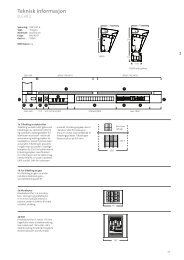
<strong>SLOT</strong> <strong>WALL</strong> <strong>BRACKET</strong><br />
<strong>SLOT</strong> UP AND DOWN <strong>WALL</strong> <strong>BRACKET</strong> For 2 fluorescent lamp TC-TEL 26/32/42W Gx24q-3/4 Art.S.3945<br />
<strong>SLOT</strong> UP AND DOWN <strong>WALL</strong> <strong>BRACKET</strong> For 2 metal halide lamp HIT-CRI 70W G12 Art.S.3946<br />
<strong>SLOT</strong> UP AND DOWN <strong>WALL</strong> <strong>BRACKET</strong> For 2 metal halide lamp HIT-CRI 150W G12 Art.S.3948 (Ta=15°C)<br />
<strong>SLOT</strong> DOWN <strong>WALL</strong> <strong>BRACKET</strong> For 2 fluorescent lamp TC-TEL 26/32/42W Gx24q-3/4 Art.S.3935<br />
<strong>SLOT</strong> DOWN <strong>WALL</strong> <strong>BRACKET</strong> For 2 metal halide lamp HIT-CRI 70W G12 Art.S.3936<br />
<strong>SLOT</strong> DOWN <strong>WALL</strong> <strong>BRACKET</strong> For 2 metal halide lamp HIT-CRI 150W G12 Art.S.3938<br />
N.B.: USE UV STOP LAMPS ONLY<br />
TECHNICAL INFORMATION<br />
Body in die-cast/extruded aluminium.<br />
Tempered glass diffuser.<br />
Stainless steel screws.<br />
Pre-phosphochromatation treatment and powder paint with high corrosion resistance.<br />
Lampholders in compliance with European Standards.<br />
Cable connection with fast-in system.<br />
Pre-wired for double switch-on.<br />
CLASS I IP 65<br />
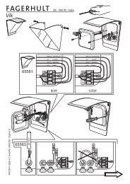
INSTALLATION INSTRUCTION<br />
RECOMMENDATIONS<br />
Do not exceed the maximum wattage-see internal label.<br />
The fitting must be earthed.<br />
Disconnect the power before maintenance.<br />
Use HAR cable.<br />
In case of glass damage, replace it before using the fitting.<br />
Do not enter with single wires into the power point connector.<br />
Minimum distance between fitting and<br />
lighted surface = 0,5m<br />
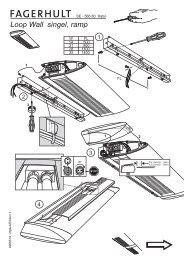
Remove the fixation plate (A) unscrewing the screws (B).<br />
Open the fitting and remove rings and glassess (C).<br />
Install the fixation plate to the wall with 3 screws (not supplied) following drawing 1.<br />
Connect the supply cable (Ø =9mm - Ø =10mm) to the power point connector (supplied) following the scheme.<br />
min max<br />
1=LIFE FOR DOWN LAMP 2=LIFE FOR UPPER LAMP (only for S.3946 and for S.3948) 3=NEUTRAL<br />
Connect the power point connector with the plug connector (pre-installed on the fitting).<br />
Insert the fitting on the fixation plate and lock the screws (B).<br />
Insert the correct lamps and adjust the reflectors as on your request (+/- 20°).<br />
Close the fitting re-installing glasses and rings (C)..<br />
NOTE<br />
The fitting is suitable to the mounting on normal flammable surfaces.<br />
Installation should be carried out by a suitably qualified person in accordance with good<br />
electrical practice and the appropriate national wiring regulations.<br />
Is very important to follow these instructions to, enable the fitting to be installed correctly.<br />
Please retain for information.<br />
0,5 m<br />
ISTR<strong>SLOT</strong>PARE REV.3 06/02<br />
03<br />
03<br />
03
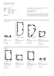
<strong>SLOT</strong> / MINI<strong>SLOT</strong> / MICRO<strong>SLOT</strong> ACCESSORIES<br />
<strong>SLOT</strong> ACCESSORY<br />
EXTENSIVE LENS Art. S.3901<br />
ELLIPSOIDAL LENS Art. S.3902<br />
RED FILTER Art. S.3906<br />
BLUE FILTER Art. S.3907<br />
YELLOW FILTER Art. S.3908<br />
GREEN FILTER Art. S.3909<br />
MINI<strong>SLOT</strong> ACCESSORY<br />
EXTENSIVE LENS Art. S.3911<br />
ELLIPSOIDAL LENS Art. S.3912<br />
RED FILTER<br />
Art. S.3916<br />
BLUE FILTER Art. S.3917<br />
YELLOW FILTER Art. S.3918<br />
GREEN FILTER Art. S.3919<br />
MICRO<strong>SLOT</strong> ACCESSORY<br />
EXTENSIVE LENS Art. S.3991<br />
ELLIPSOIDAL LENS Art. S.3992<br />
RED FILTER<br />
Art. S.3996<br />
BLUE FILTER Art. S.3997<br />
YELLOW FILTER Art. S.3998<br />
GREEN FILTER Art. S.3999<br />
Tempered glass diffuser<br />
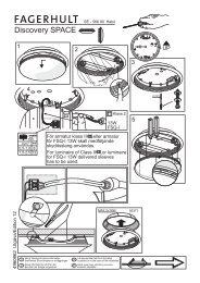
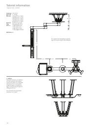
INSTALLATION INSTRUCTIONS<br />
Open the fitting and remove the ring and the glass (Pic. A).<br />
Place the accessory in the seat of the gasket (Pic. B).<br />
Install glass + accessory leaving the accessory in the internal side of fitting (Pic. C).<br />
Close the fitting.<br />
REMARKS<br />
RING<br />
GLASS<br />
GLASS<br />
RING<br />
RING<br />
GLASS<br />
ACCESSORY<br />
ACCESSORY<br />
GLASS<br />
RING<br />
Pic. A Pic. B Pic. C<br />
Disconnect the power before maintenance.<br />
In case of glass damage, replace it before using the fitting.<br />
Is very important to follow these instructions to, enable the fitting to be installed correctly.<br />
Please retain for information.<br />
RING<br />
GLASS +<br />
ACCESSORY<br />
GLASS +<br />
ACCESSORY<br />
RING<br />
ISTR<strong>SLOT</strong>ACC REV.2 10/02