Physics 215 - Experiment 8 Electric Fields and Potentials
Physics 215 - Experiment 8 Electric Fields and Potentials
Physics 215 - Experiment 8 Electric Fields and Potentials

You also want an ePaper? Increase the reach of your titles
YUMPU automatically turns print PDFs into web optimized ePapers that Google loves.
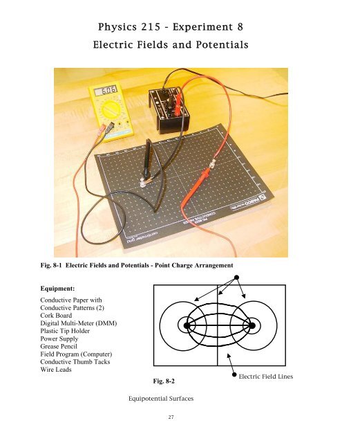
<strong>Physics</strong> <strong>215</strong> - <strong>Experiment</strong> 8<br />
<strong>Electric</strong> <strong>Fields</strong> <strong>and</strong> <strong>Potentials</strong><br />
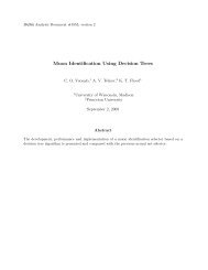
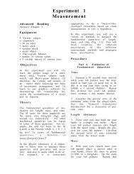
Fig. 8-1 <strong>Electric</strong> <strong>Fields</strong> <strong>and</strong> <strong>Potentials</strong> - Point Charge Arrangement<br />
Equipment:<br />
Conductive Paper with<br />
Conductive Patterns (2)<br />
Cork Board<br />
Digital Multi-Meter (DMM)<br />
Plastic Tip Holder<br />
Power Supply<br />
Grease Pencil<br />
Field Program (Computer)<br />
Conductive Thumb Tacks<br />
Wire Leads<br />
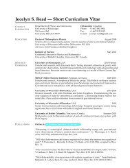
Fig. 8-2<br />
<strong>Electric</strong> Field Lines<br />
Equipotential Surfaces<br />
27
<strong>Physics</strong> <strong>215</strong> - <strong>Experiment</strong> 8<br />
<strong>Electric</strong> <strong>Fields</strong> <strong>and</strong> <strong>Potentials</strong><br />
Advance Reading<br />
Urone, Chapter 17, sections 17-4 through 17-<br />
6; Chapter 18, Sections 18.1 through 18-4.<br />
Appendix C: Equipment DMM.<br />
Objective: The objective of this lab is to<br />
map equipotential lines <strong>and</strong> field lines of<br />
point charges <strong>and</strong> parallel plates.<br />
Theory: An electric field, E, at a point is<br />
defined as the force per unit charge at the<br />
point:<br />
<strong>Electric</strong> field lines point in the direction of<br />
maximum decrease in potential.<br />
An equipotential surface is defined as a<br />
surface where all points on the surface have<br />
the same electric potential. To move a<br />
charge around on such a surface requires no<br />
work. In two-dimensions the equipotential<br />
surfaces are equipotential lines. How close<br />
the lines are to each other is an indication of<br />
the field strength. <strong>Electric</strong> field lines are<br />
always perpendicular to equipotential lines.<br />
E = F/q (Eq. 8-1)<br />
The electric field is represented by lines of<br />
force drawn to follow the direction of the<br />
field.<br />
The electric potential is defined as the<br />
potential energy per unit charge, however,<br />
we can only measure the difference in<br />
potential energy between two points. This<br />
change in potential energy per unit charge<br />
(the voltage, V ba ) is equal to the work done<br />
by the electric force to move a charge from<br />
one point to another:<br />
V ba = V b - V a = W/q (Eq. 8-2)<br />
The two conductive patterns, point charges<br />
<strong>and</strong> parallel plates, are on<br />
conductive/resistive paper. Perfectly<br />
conducting paper would have zero potential<br />
difference between two points. The paper<br />
tends to concentrate the electric field into<br />
the plane of the paper.<br />
Procedure<br />
Set Up <strong>and</strong> Connections<br />
1. Place the point charge pattern (two dots)<br />
on the corkboard. Push a pin into the<br />
center of each point charge.<br />
2. Unplug <strong>and</strong> turn off the power supply.<br />
Refer to Fig. 8-1 <strong>and</strong> 8-3: connect the<br />
power supply to the point charges.<br />
28
<strong>Physics</strong> <strong>215</strong> - <strong>Experiment</strong> 8<br />
<strong>Electric</strong> <strong>Fields</strong> <strong>and</strong> <strong>Potentials</strong><br />
Fig.8-3 Banana-Alligator Wire Lead<br />
Use the banana connector on the power<br />
supply, alligator connector on the pins.<br />
3. Refer to Fig. 8-1 <strong>and</strong> Fig. C-9: connect<br />
the ground lead (black) from the DMM<br />
to the negative point charge (black<br />
wire). Connect the positive lead (red) of<br />
the DMM from the "V" jack of the<br />
DMM to the positive point charge (red<br />
wire).<br />
4. Turn the DMM on; turn the dial to 20 on<br />
the DCV (voltage) scale. This means the<br />
DMM (voltmeter) is configured to<br />
measure voltage up to 20V. Plug in the<br />
power supply; increase the power until<br />
the voltmeter reads 6.0V. Label the<br />
point charges with the grease pencil (i.e.,<br />
the ground from the power supply is at<br />
0.0V <strong>and</strong> the positive lead from the<br />
power supply is at 6.0V).<br />
Equipotential Lines: Point Charges<br />
5. Hold the DMM ground lead on the 0.0V<br />
point charge. Watch the voltmeter as<br />
you move the positive lead across the<br />
conductive sheet.<br />
6. Keeping the ground lead at the 0.0V<br />
point charge, find at least four equally<br />
spaced points where the voltmeter reads<br />
1.0V. As you locate each point, press<br />
the tip of the lead into the sheet to leave<br />
an indentation. After finding the four<br />
points, "connect the dots" using the<br />
grease pencil. Label the equipotential<br />
line as 1.0V.<br />
7. Repeat Step 6 for 3.0V , 4.0V & 5.0V.<br />
Each lab partner should draw one set of<br />
equipotential lines.<br />
8. Place the DMM leads into the plastic tip<br />
holder <strong>and</strong> measure the potential<br />
difference across the 3.0V equipotential<br />
line. Calculate the field strength at this<br />
location in V/m.<br />
9. Use the grease pencil to mark the<br />
position where you measured the field<br />
strength, then record the value on the<br />
conductive paper.<br />
29
<strong>Physics</strong> <strong>215</strong> - <strong>Experiment</strong> 8<br />
<strong>Electric</strong> <strong>Fields</strong> <strong>and</strong> <strong>Potentials</strong><br />
<strong>Electric</strong> Field Lines - Point Charges<br />
10. Place the DMM leads in the plastic tip<br />
holder. Place the ground lead as close to<br />
the 0.0V point charge as possible, just<br />
off- center of a line that would connect<br />
the two point charges. As you pivot the<br />
positive lead around the ground lead,<br />
watch the values on the voltmeter.<br />
When you have located the position of<br />
maximum value, press an indentation<br />
into the paper with the red lead. Now<br />
"walk" the leads across the paper by<br />
placing the ground lead into the<br />
indentation you made with the positive<br />
lead. When you reach the 6.0V point<br />
charge, "connect the dots" with the<br />
grease pencil.<br />
11. Your partner will repeat Step 10,<br />
beginning from a different position<br />
around the 0.0V point charge. Are your<br />
field lines perpendicular to the<br />
equipotential lines?<br />
Steps 1-4: Connect the power supply<br />
<strong>and</strong> DMM to the parallel plate pattern.<br />
Set the potential difference to 6.0V.<br />
13. Refer to Step 8 <strong>and</strong> Step 9. Measure the<br />
field strength at the geometric center of<br />
the parallel plate.<br />
Equipotential Lines<br />
14. Locate the 2.0V equipotential line near<br />
the edge of the plate configuration (refer<br />
to Step 6). Find three more points<br />
outside the end of the parallel plate that<br />
are at 2.0V potential. Connect the dots.<br />
15. Your partner repeats for 4.0V.<br />
Questions<br />
1. Use dimensional analysis to show that<br />
the electric field unit of N/C equals V/m.<br />
(Urone, Section. 18.1.)<br />
2. How does Figure 18.8 in your text<br />
compare to the point charge sheet you<br />
produced?<br />
Measuring <strong>Electric</strong> Field Strength -<br />
Parallel Plates<br />
12. Refer to Figure 18.10 in your textbook.<br />
If you repeated Steps 6-11 for the<br />
parallel plate configuration, it would be<br />
similar to this illustration. Refer to<br />
30