Atmosphere-Ionosphere Mission - Swedish Institute of Space ...
Atmosphere-Ionosphere Mission - Swedish Institute of Space ...
Atmosphere-Ionosphere Mission - Swedish Institute of Space ...

Create successful ePaper yourself
Turn your PDF publications into a flip-book with our unique Google optimized e-Paper software.
ORBITS AND PAYLOADS 20<br />
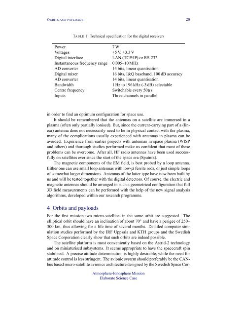
TABLE 1: Technical specification for the digital receivers<br />
Power<br />
7 W<br />
Voltages<br />
+5 V, +3.3 V<br />
Digital interface<br />
LAN (TCP/IP) or RS-232<br />
Instantaneous frequency range 0.005–10 MHz<br />
AD converter<br />
14 bits, linear quantisation<br />
Digital mixer<br />
16 bits, I&Q baseband, 100 dB accuracy<br />
AD converter<br />
14 bits, linear quantisation<br />
Bandwidth<br />
1 Hz to 196 kHz (-3 dB) selectable<br />
Centre frequency Switchable every 50µs<br />
Inputs<br />
Three channels in parallel<br />
in order to find an optimum configuration for space use.<br />
It should be remembered that the antennas on a satellite are immersed in a<br />
plasma (<strong>of</strong>ten only partially ionised). But, since the current-carrying part <strong>of</strong> a (linear)<br />
antenna does not necessarily need to be in physical contact with the plasma,<br />
many <strong>of</strong> the complications usually experienced with antennas in plasma can be<br />
avoided. Experience from earlier projects with antennas in space plasma (WISP<br />
and others) and thorough studies performed make us confident that most <strong>of</strong> these<br />
problems can be overcome. After all, HF radio antennas have been used successfully<br />
on satellites ever since the start <strong>of</strong> the space era (Sputnik).<br />
The magnetic components <strong>of</strong> the EM field, is best probed by a loop antenna.<br />
Either one can use small loop antennas with low-µ ferrite rods, or just simple loops<br />
<strong>of</strong> somewhat larger dimensions. Antennas <strong>of</strong> the latter type have now been built by<br />
us and will be tested together with the digital detectors. Of course, the electric and<br />
magnetic antennas should be arranged in such a geometrical configuration that full<br />
3D field measurements can be performed with the help <strong>of</strong> the new signal analysis<br />
algorithms, developed within our research programme.<br />
4 Orbits and payloads<br />
For the first mission two micro-satellites in the same orbit are suggested. The<br />
elliptical orbit should have an inclination <strong>of</strong> about 70 ◦ and have a perigee <strong>of</strong> 250–<br />
300 km, thus allowing for a life time <strong>of</strong> several months. Detailed computer simulation<br />
studies performed by the IRF Uppsala and KTH groups and the <strong>Swedish</strong><br />
<strong>Space</strong> Corporation clearly show that such orbits are indeed possible.<br />
The satellite platform is most conveniently based on the Astrid-2 technology<br />
and on miniaturised subsystems. It seems appropriate to have the spacecraft spin<br />
stabilised. A precise attitude determination is highly desirable, while the need for<br />
attitude control is less stringent. The avionic system should preferably be the CANbus<br />
based micro-satellite avionics architecture designed by the <strong>Swedish</strong> <strong>Space</strong> Cor-<br />
<strong>Atmosphere</strong>-<strong>Ionosphere</strong> <strong>Mission</strong><br />
Elaborate Science Case