Self Inductance of a Solenoid with a Permanent-Magnet Core 1 ...
Self Inductance of a Solenoid with a Permanent-Magnet Core 1 ...
Self Inductance of a Solenoid with a Permanent-Magnet Core 1 ...

You also want an ePaper? Increase the reach of your titles
YUMPU automatically turns print PDFs into web optimized ePapers that Google loves.
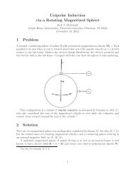
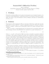
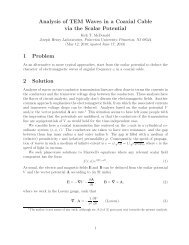
1 Problem<br />
<strong>Self</strong> <strong>Inductance</strong> <strong>of</strong> a <strong>Solenoid</strong><br />
<strong>with</strong> a <strong>Permanent</strong>-<strong>Magnet</strong> <strong>Core</strong><br />
Kirk T. McDonald<br />
Joseph Henry Laboratories, Princeton University, Princeton, NJ 08544<br />
(March 3, 2013; updated March 20, 2013)<br />
Deduce the self inductance L <strong>of</strong> a solenoidal coil <strong>of</strong> N turns <strong>of</strong> radius r and length l ≫ r<br />
when its core is a cylinder <strong>with</strong> permanent-magnetization density M parallel to the solenoid<br />
axis. Consider a quasistatic current I(t) in the coil, and comment on the magnetic energy<br />
stored in the system, and the EMF across the coil.<br />
2 Solution<br />
In the limit <strong>of</strong> large l/r the magnetic field due to the permanent magnetization density<br />
M = M ẑ is (in SI units) 1 ⎧<br />
⎪⎨ μ 0 M = μ 0 M ẑ (inside),<br />
B M ≈<br />
⎪⎩ 0 (outside).<br />
(1)<br />
In the quasistatic approximation, where radiation is neglected, it seems reasonable to suppose<br />
that the magnetic field due to the current I(t) is 2<br />
⎧<br />
⎪⎨ μ 0 NI ẑ/l (inside),<br />
B I ≈<br />
(2)<br />
⎪⎩ 0 (outside).<br />
The energy stored in the magnetic field B I , which is significant only inside the volume πr 2 l<br />
<strong>of</strong> the cylinder, is given by<br />
∫ B<br />
2<br />
U I = I<br />
dVol ≈ 1 μ 0 πN 2 r 2<br />
I 2 . (3)<br />
2μ 0 2 l<br />
Stored energy <strong>of</strong> the form (3) holds whenever the magnetic field is due to electrical<br />
currents that have started up from zero. This example includes permanent magnetism,<br />
which can be thought <strong>of</strong> as due to permanent “supercurrents” that do not change as the<br />
current I in the rest <strong>of</strong> the circuit varies.<br />
We recall that the force on a small magnetic dipole m in an external magnetic field B ext<br />
is 3 F = ∇(m · B ext )=−∇U m , where U m = −m · B ext . (4)<br />
1 See, for example, pp. 93-94 <strong>of</strong> [1].<br />
2 The direction <strong>of</strong> the z-axis is chosen such that eq. (2) holds. Then, for negative M, B M is antiparallel<br />
to B I .<br />
3 See,forexample,p.87<strong>of</strong>[2].<br />
1
If the permanent magnet in the present example is held at rest <strong>with</strong> respect to the<br />
surrounding coil (<strong>with</strong> any fixed relation between the directions <strong>of</strong> the magnetization M<br />
and the field B I <strong>of</strong> the coil), no work is done by the sum <strong>of</strong> the forces (4) on the magnetic<br />
dipoles in the magnet as the magnetic field increases from zero. Although the quantity U m<br />
<strong>of</strong> eq. (4) changes in this process, this quantity does not correspond to a change in energy<br />
<strong>of</strong> the system. Hence, we can say that to <strong>with</strong>in a constant the total energy stored in the<br />
system (other than in the power source <strong>of</strong> the electrical currents) is simply that given by<br />
eq. (3), which can be written in the familiar form<br />
where the self inductance L 0 <strong>of</strong> the coil is<br />
U I = 1 2 LI 2 , (5)<br />
L = μ 0πN 2 r 2<br />
, (6)<br />
l<br />
which is the same as if the permanent magnet were not present.<br />
2.1 The <strong>Permanent</strong> <strong>Magnet</strong> Can Move <strong>with</strong> Respect to the Coil<br />
It could also be that the permanent magnet is not fixed in place <strong>with</strong> respect to the coil as<br />
the latter is energized. As the field inside a solenoid coil is rather uniform, the force (4) on<br />
the coil is small, and we neglect it. However, if the total magnetic moment MV M ,where<br />
V M is the volume <strong>of</strong> the magnet, is not parallel to the magnetic field B I <strong>of</strong> the coil, the<br />
permanent magnet experiences a torque,<br />
τ = MV M × B I = B MV M<br />
× B I , (7)<br />
μ 0<br />
and will rotate as a consequence if the motion <strong>of</strong> the magnet is unconstrained.<br />
However, if the cylindrical magnet is constrained to rotate only about its symmetry axis,<br />
which has a fixed direction (parallel to the magnetization M), then the torque (7) has no<br />
component along the axis <strong>of</strong> rotation and does not influence the rotation <strong>of</strong> the magnet; the<br />
quantity U M = −MV M · B I does not have the significance <strong>of</strong> a stored energy that can affect<br />
the self inductance <strong>of</strong> the coil.<br />
Suppose instead that the cylindrical magnet is constrained to rotate about an axis perpendicular<br />
to its symmetry axis (which is parallel to the magnetization M), <strong>with</strong> the axis<br />
<strong>of</strong> rotation being fixed perpendicular to the symmetry axis <strong>of</strong> the coil. Let θ be the variable<br />
angle between M and B I and I mech be the moment <strong>of</strong> inertia <strong>of</strong> the magnet about the its<br />
(fixed) axis <strong>of</strong> rotation. The rotational equation <strong>of</strong> motion <strong>of</strong> the magnet is<br />
d 2 θ<br />
I mech<br />
dt = τ = −B MV M μ 0 NI(t)<br />
sin θ = − NB MV M I(t)<br />
sin θ (8)<br />
2 μ 0 l<br />
l<br />
If the initial angle is θ 0 and we write θ = θ 0 + ϑ, then the equation <strong>of</strong> motion (8) can be<br />
written as<br />
I mech<br />
d 2 ϑ<br />
dt 2<br />
= −NB MV M I(t)<br />
(sin θ 0 cos ϑ +cosθ 0 sin ϑ). (9)<br />
l<br />
2
In an AC circuit where the coil is in series <strong>with</strong> a resistor R and the current is I(t) =I 0 cos ωt,<br />
the equation <strong>of</strong> motion <strong>of</strong> the permanent magnet becomes<br />
This has the oscillatory solution,<br />
d 2 ϑ<br />
dt 2 = −NB MV M I 0<br />
lI mech<br />
cos ωt(sin θ 0 cos ϑ +cosθ 0 sin ϑ). (10)<br />
cos θ 0 =0, sin θ 0 = ±1, ϑ = ϑ 0 cos ωt, ϑ 0 =sinθ 0<br />
NB M V M I 0<br />
ω 2 lI mech<br />
, (11)<br />
for small ϑ 0 . The voltage source V (t) does mechanical work on the rotating magnet at rate<br />
P mech = d dt I mech ˙ϕ 2 = τ ˙ϕ ≈ − NB MV M I 0 cos ωt<br />
l<br />
(<br />
)<br />
NB M V M I 0<br />
sin θ 0 −ω sin θ 0 cos ωt<br />
ω 2 lI mech<br />
= N 2 BMV 2 M<br />
2 I<br />
ωl 2 0 2 cos ωt sin ωt, (12)<br />
I mech<br />
so the total power provided by the source is, recalling eq. (5), 4<br />
P = VI = I 2 R + dU I<br />
dt + P mech = I 2 R + LII ˙ + N 2 BM 2 V M<br />
2 I<br />
ωl 2 0 2 cos ωt sin ωt<br />
I<br />
[ (<br />
mech<br />
= I IR + L − N 2 BM 2 V M<br />
2 ) ]<br />
I˙ . (13)<br />
ω 2 l 2 I mech<br />
If we now switch to complex notation, writing V = V 0 e iωt , I = I 0 e iωt <strong>with</strong> a I 0 complex<br />
constant, then I ˙ = iωI and the impedance Z <strong>of</strong> the system is<br />
Z = V I = R + iωL + N 2 B 2 MV 2 M<br />
iωl 2 I mech<br />
≡ R + iωL + 1<br />
iωC . (14)<br />
We can say that the effect <strong>of</strong> the oscillating permanent magnet on the system is not to<br />
change the self inductance (6) <strong>of</strong> the coil, but to give it a capacitance, 5<br />
C =<br />
l2 I mech<br />
N 2 B 2 MV 2 M<br />
. (15)<br />
The system behaves like a series R-L-C circuit, <strong>with</strong> resonant angular frequency<br />
ω 0 = 1 √<br />
LC<br />
=<br />
B M V M<br />
√μ 0 πlr 2 I mech<br />
, (16)<br />
4 We might also consider two other forms <strong>of</strong> energy related to the present system, the interaction magneticfield<br />
energy, U int ≈ B I ·B M V m /µ 0 , and the magnetic-moment energy U M = −MV M ·B I = −B I ·B M V m /µ 0 =<br />
−U int . Since these add to zero we do not consider them further. A similar conclusion is reached at the end<br />
<strong>of</strong> sec. III.5 <strong>of</strong> [3].<br />
5 Variants <strong>of</strong> “flywheels” have long been used as energy storage devices in mechanical systems, and also in<br />
electromechanical systems such as motor-generator sets. These devices utilize more or less steady rotation,<br />
in contrast to the rotational oscillations in the present example.<br />
3
at which frequency the magnitude <strong>of</strong> the current is maximal, <strong>with</strong> I 0 = V 0 /R.<br />
Electromechanical resonances have been observed in the apparatus described in [4] (private<br />
communication, David J. Jefferies). The capacitance induced by a rotating magnetic<br />
field underlies the sensor described in [5].<br />
The magnet can also make full rotations, driven by the AC power source, in which case<br />
the system is a kind <strong>of</strong> single-phase motor, as first demonstrated by Bally [6] in 1879.<br />
References<br />
[1] K.T. McDonald, Electricity and <strong>Magnet</strong>ism, Lecture 8,<br />
http://puhep1.princeton.edu/~mcdonald/examples/ph501/ph501lecture8.pdf<br />
[2] K.T. McDonald, Electricity and <strong>Magnet</strong>ism, Lecture 7,<br />
http://puhep1.princeton.edu/~mcdonald/examples/ph501/ph501lecture7.pdf<br />
[3] A. O’Rahilly, Electromagnetic Theory, Vol. I (Longmans, Green, 1938; Dover, 1965).<br />
[4] M.N. Wybourne et al., Frequency-crossing phonon spectrometer techniques, Rev. Sci.<br />
Instr. 50, 1634 (1979),<br />
http://puhep1.princeton.edu/~mcdonald/examples/detectors/wybourne_rsi_50_1634_79.pdf<br />
[5] F.-M. Hsu et al., A Novel <strong>Magnet</strong>ic-Induced Capacitive-Sensing Rotation Sensor, IEEE<br />
Sensors, 1 (2012),<br />
http://puhep1.princeton.edu/~mcdonald/examples/EM/hsu_ieeesensors_1_12.pdf<br />
[6] W. Bally, A Mode <strong>of</strong> producing Arago’s Rotation, Proc. Phys. Soc. London 3, 115<br />
(1879), http://puhep1.princeton.edu/~mcdonald/examples/EM/bally_ppsl_3_115_79.pdf<br />
4