P-7000 - Accuphase
P-7000 - Accuphase
P-7000 - Accuphase

Create successful ePaper yourself
Turn your PDF publications into a flip-book with our unique Google optimized e-Paper software.
m Powerful 11-parallel push-pull output stage in each channel delivers<br />
linear power into loads as low as one ohm m Input stage with MCS<br />
topology m Current feedback circuit combines excellent sound quality<br />
with total operation stability m Bridged connection mode allows upgrading<br />
to true monophonic amplifier m Massive Super Ring toroidal transformer<br />
rated for 1.5 kVA m Printed circuit boards made from Teflon material
A stereo power amplifier with impressive punch: 1,000 watts into 1 ohm<br />
MCS technology in input stage improves S/N ratio, distortion ratings and<br />
other characteristics. 11 pairs of wide-band high-power transistors in parallel<br />
push-pull configuration for each channel. Power supply with massive 1.5 kVA<br />
toroidal power transformer supports linear power down to impedances as<br />
low as one ohm. Teflon PCBs with low dielectric constant and minimum loss.<br />
The P-<strong>7000</strong> continues the distinguished design policy<br />
of the M-8000. It adds MCS technology in the input<br />
stage and many other refinements. Carefully<br />
selected top quality parts are used throughout. The<br />
design aim was to achieve very low output impedance<br />
(Note 1) and constant drive voltage (Note 2). The<br />
end result is a stereo power amplifier that provides<br />
effortless performance and impeccable sound quality.<br />
In the output stage, 11 pairs of high-power<br />
transistors with a rated collector dissipation of 150<br />
watts are arranged in a parallel push-pull<br />
configuration for each channel. The devices are<br />
mounted to large heat sinks on both sides of the<br />
main chassis for efficient dissipation of thermal<br />
energy generated during operation. As a result, the<br />
amplifier is capable of delivering power in a linear<br />
progression towards lower load impedances: 1,000<br />
watts into 1 ohm, 500 watts into 2 ohms, 250 watts<br />
into 4 ohms and 125 watts into 8 ohms. Speakers<br />
with very low impedances as well as speakers whose<br />
impedance fluctuates drastically can also be driven<br />
with ease. By using the P-<strong>7000</strong> in bridged mode, it<br />
is possible to create a monophonic amplifier with<br />
even higher power. This performance is sustained<br />
Note 1: Low amplifier output impedance<br />
When forming the load of a power amplifier, a loudspeaker generates<br />
a counterelectromotive force that can flow back into the amplifier<br />
via the NF loop. This phenomenon is influenced by fluctuations in<br />
speaker impedance, and interferes with the drive performance of<br />
the amplifier. The output impedance of a power amplifier should<br />
therefore be made as low as possible by using output devices<br />
with high current capability. This absorbs the counterelectromotive<br />
force generated by the voice coil and prevents the occurrence of<br />
intermodulation distortion.<br />
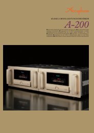
Note 2: Constant drive voltage principle<br />
Even when the impedance of a load fluctuates drastically, the<br />
ideal power amplifier should deliver a constant voltage signal to<br />
the load. Figure 2 is a graph plotting the output voltage versus<br />
current characteristics. Even when the load changes, the output<br />
voltage remains almost constant, showing linear current<br />
progression. Actual measurement of clipping power at the<br />
extremely low load impedance of 1 ohm yields 1,050 watts. At 2<br />
ohms, the figure is 606 watts, at 4 ohms 326 watts, and at 8 ohms<br />
170 watts. This demonstrates the impressive performance reserves<br />
of this amplifier.<br />
by a massive Super Ring toroidal transformer housed<br />
in a diecast enclosure with directly mounted heat<br />
sinks, and by large filtering capacitors. The<br />
transformer is rated for 1.5 kVA, and there are two<br />
capacitors of 56,000 µF each. This assures more<br />
than ample reserves and allows the amplifier to<br />
meet even the most demanding and rapidly<br />
fluctuating power requirements.<br />
The important input stage also has been given due<br />
attention. Another <strong>Accuphase</strong> innovation called MCS<br />
(Multiple Circuit Summing) helps to minimize noise.<br />
Current feedback topology combines total operation<br />
stability with excellent frequency response, while<br />
requiring only minimum amounts of negative<br />
feedback. The material used for printed circuit boards<br />
has a decisive influence not only on electrical<br />
characteristics but also on the sonic end result.<br />
The P-<strong>7000</strong> uses Teflon boards with extremely low<br />
dielectric constant and low loss. The copper foil<br />
side of PCBs and all input and output terminals as<br />
well as all major signal carrying points are gold<br />
plated. Balanced inputs help to shut out external<br />
noise. The overall result of these measures is musical<br />
purity that leaves nothing to be desired.<br />
Output current (A)<br />
Output voltage (V)<br />
* 1-ohm operation possible with<br />
music signals only<br />
Fig. 2 Output power vs. load impedance<br />
(output voltage/output current: actual measurements)<br />
11-parallel push-pull power unit delivers guaranteed<br />
linear power output of 1,000 watts into 1 ohm, 500<br />
watts into 2 ohms, 250 watts into 4 ohms and 125<br />
watts into 8 ohms<br />
The output stage uses high-power transistors with a<br />
rated collector dissipation of 150 watts and collector<br />
current of 15 amperes. These devices boast excellent<br />
frequency response, current amplification linearity,<br />
and switching characteristics. The transistors are<br />
arranged in an 11-parallel push-pull configuration<br />
(Figure 1) for ultra-low impedance and mounted on a<br />
massive heat sink made from diecast aluminum. This<br />
assures effective heat dissipation and allows the<br />
amplifier to effortlessly handle very low impedances.<br />
Power linearity is maintained down to loads as low as<br />
1 ohm, which demonstrates the impressive<br />
capabilities of this amplifier.<br />
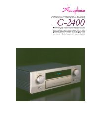
MCS topology in input stage drastically improves<br />
S/N ratio, distortion, and other characteristics<br />
The input stage features <strong>Accuphase</strong>'s original MCS<br />
(Multiple Circuit Summing-up) design. Three separate<br />
BIAS STABILIZER<br />
CIRCUIT<br />
REGULATOR<br />
+ B 1<br />
unit amplifiers for the input signal are connected in<br />
parallel, which minimizes noise and<br />
distortion and greatly improves other<br />
performance parameters as well. This<br />
manifests itself in further improved<br />
sound quality.<br />
MCS<br />
(Multiple Circuit Summing-up)<br />
Q 15<br />
Q 21 Q 23 Q 25 Q 27 Q 29 Q 31 Q 33 Q 35 Q 37 Q 39 Q 41 Q 43<br />
+ B 2<br />
Current feedback circuit topology<br />
prevents phase shifts in high<br />
frequency range<br />
Q 1-4<br />
IC 1<br />
– INPUT<br />
+ INPUT<br />
Q 5-8 IC 2<br />
Q 9-12<br />
IC 3<br />
BIAS STABILIZER<br />
CIRCUIT<br />
Q 19<br />
13<br />
Q 17<br />
NFB<br />
NETWORK<br />
+Q<br />
OUTPUT<br />
–<br />
BIAS STABILIZER CIRCUIT<br />
Q 18<br />
Q14<br />
Q Q22 Q 24<br />
20<br />
Q 26 Q 28 Q 30 Q 32 Q 34 Q 36 Q 38 Q 40 Q 42 Q 44<br />
Q 16<br />
REGULATOR<br />
– B 1<br />
Fig. 1 Circuit diagram of amplifier section (one channel)<br />
– B 2<br />
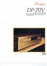
The P-<strong>7000</strong> employs the original<br />
<strong>Accuphase</strong> current feedback principle.<br />
At the sensing point of the feedback<br />
loop, the impedance is kept low and<br />
current detection is performed. An<br />
impedance-converting amplifier then<br />
turns the current into a voltage to be<br />
used as the feedback signal. Since<br />
the impedance at the current<br />
feedback point (current adder in<br />
Figure 3) is very low, there is almost<br />
no phase shift. Phase compensation<br />
can be kept to a minimum, resulting<br />
in excellent transient response and
– Input<br />
+ Input<br />
Buffer<br />
Current<br />
adder<br />
I-V<br />
converter<br />
Trans-impedance<br />
amplifier<br />
Current NFB<br />
network<br />
Amplifier<br />
Fig. 3 Principle of current feedback amplifier<br />
Output<br />
superb sonic transparency. Minimal amounts of NFB<br />
are used for maximum effect, providing natural energy<br />
response.<br />
Figure 4 shows<br />
frequency<br />
response for<br />
different gain<br />
settings of the<br />
c u r r e n t<br />
feedback<br />
amplifier. The<br />
g r a p h s<br />
demonstrate<br />
that response remains<br />
uniform over a wide<br />
range.<br />
Fig. 4 Frequency response with current feedback<br />
(Response remains uniform even when gain changes)<br />
Printed circuit boards made from Teflon with low<br />
dielectric constant and low loss<br />
The printed circuit boards for the signal-carrying<br />
circuits are made of Teflon, a glass fluorocarbon<br />
resin material. Teflon has extremely low specific<br />
inductive capacity which is desirable for fast signal<br />
transmission. The low dielectric dissipation factor<br />
results in minimal transmission losses. High-frequency<br />
characteristics and heat resistance are also excellent.<br />
For further improved sound quality, the copper foil<br />
side is gold plated.<br />
* Teflon is a registered trademark of DuPont USA.<br />
n Power amplifier assembly with 11 parallel<br />
push-pull transistor pairs per channel<br />
mounted directly to large aluminum diecast<br />
heat sinks, MCS circuitry, and current<br />
feedback amplifier<br />
Robust power supply with “Super Ring” toroidal<br />
transformer and high filtering capacity<br />
The P-<strong>7000</strong> features a massive toroidal power transformer<br />
with a maximum rating of 1.5 kVA. The transformer<br />
is housed<br />
in a non-resonant<br />
aluminum case<br />
filled with a material<br />
that transmits<br />
heat and absorbs<br />
vibrations. This<br />
completely prevents<br />
any adverse<br />
influences<br />
on other circuit<br />
parts. A toroidal<br />
transformer uses<br />
heavy-gauge copper<br />
wiring on a<br />
doughnut-shaped<br />
core. This results<br />
in low impedance<br />
and high efficiency,<br />
while allowing<br />
compact<br />
dimensions.<br />
Two ultra-large aluminum electrolytic capacitors rated<br />
for 56,000 µF each serve to smooth out the pulsating<br />
direct current from the rectifier, providing more than<br />
ample filtering capacity.
Bridged connection allows upgrading to a true<br />
monophonic amplifier with 2,000 watts into 2<br />
ohms, 1,000 watts into 4 ohms, and 500 watts<br />
into 8 ohms.<br />
Bridged connection results in a monophonic<br />
amplifier with four times the power output<br />
compared to stereo operation. Dynamic power<br />
with an almost unlimited feel is the result.<br />
Easy switching between dual mono operation<br />
and bridged connection<br />
A mode selector on the<br />
rear panel makes it<br />
simple to switch<br />
between dual mono,<br />
stereo, or bridged<br />
operation.<br />
n Balanced connection prevents induced noise<br />
n PCB copper foil and all major signal path<br />
components are gold-plated<br />
n Large direct-reading analog<br />
power meters<br />
n Oversize speaker terminals<br />
accept also very heavy-gauge<br />
speaker cable<br />
Assembly with meter and protection circuitry<br />
Unbalanced and balanced input<br />
connectors<br />
Large size speaker terminals<br />
Gold-plated parts<br />
High-quality, high-reliability parts<br />
n Front panel<br />
Parallel drive of output devices<br />
Semiconductor devices for high frequency applications usually employ a multi-chip design<br />
where a number of small transistors or FETs are connected in parallel. This approach allows<br />
reducing inherent impedance and residual noise as compared to single device operation. In<br />
other words, linearity is improved. In physical terms, increasing the surface area of the chip<br />
prevents spot overheating by providing better heat dissipation, resulting in more stable operation.<br />
Parallel connection in the output stage of the P-<strong>7000</strong> uses a similar principle for distributing<br />
the current, which lets the amplifier easily deal with sudden demands for high current, such<br />
as caused by pulsive source signals. However, a parallel circuit as implemented by <strong>Accuphase</strong><br />
is much more than a simple physical connection. <strong>Accuphase</strong>'s extensive know-how gained<br />
through many years of intensive research and experimentation is in evidence here. Careful<br />
control of temperature characteristics, current matching of individual devices, and many other<br />
advanced measures are implemented. The overall result is minimized distortion at low currents<br />
and improved S/N ratio, which manifests itself as dramatically improved clarity and transparency<br />
at low listening levels. Ample current reserves make it possible to drive even extremely low<br />
loads with effortless authority. No-holds-barred performance and superb sound are the hallmarks<br />
of <strong>Accuphase</strong> amplifiers.<br />
n Rear panel<br />
A Power meters<br />
(Output indication in dB and %)<br />
B Meter operation/illumination switch<br />
ON OFF<br />
C Power switch<br />
D Speaker output terminals<br />
E Mode selector<br />
DUAL MONO NORMAL BRIDGE<br />
F Unbalanced inputs<br />
Remarks<br />
H This product is available in versions for 120/230 V AC. Make sure that the voltage shown on<br />
the rear panel matches the AC line voltage in your area.<br />
H The shape of the AC inlet and plug of the supplied power cord, and the circuit breaker<br />
current rating depend on the voltage rating and destination country.<br />
H<br />
H<br />
G Balanced inputs<br />
a Ground<br />
b Inverted (–)<br />
c Non-inverted (+)<br />
H Input selector<br />
BALANCE UNBALANCE<br />
I AC circuit breaker H<br />
J AC input connector H<br />
(for supplied power cord)<br />
GUARANTEED SPECIFICATIONS<br />
[Guaranteed specifications are measured according to EIA standard RS-490.]<br />
m Continuous Average Output Power (20 - 20,000 Hz)<br />
Stereo operation<br />
1,000 watts per channel into 1 ohm (✽)<br />
(both channels driven)<br />
0 500 watts per channel into 2 ohms<br />
0 250 watts per channel into 4 ohms<br />
0 125 watts per channel into 8 ohms<br />
Monophonic operation<br />
2,000 watts into 2 ohms (✽)<br />
(bridged connection)<br />
1,000 watts into 4 ohms<br />
0 500 watts into 8 ohms<br />
Note: The rating marked (✽) is for music signals only.<br />
m Total Harmonic Distortion Stereo operation (both channels driven)<br />
0.05%, with 2 ohm load<br />
0.03%, with 4 to 16 ohm load<br />
Monophonic operation (bridged connection)<br />
0.03%, with 4 to 16 ohm load<br />
m Intermodulation Distortion 0.003%<br />
m Frequency Response At rated output: 20 - 020,000 Hz +0, –0.2 dB<br />
At 1 watt output: 0.5 - 160,000 Hz +0, –3.0 dB<br />
m Gain<br />
28.0 dB (in stereo and monophonic operation)<br />
m Output Load Impedance Stereo operation: 2 to16 ohms H Driving 1Ω loads in stereo operation<br />
and 2Ω loads in monophonic operation<br />
Monophonic operation: 4 to16 ohms is possible with music signals only.<br />
m Damping Factor<br />
300 (stereo/monophonic operation)<br />
m Input Sensitivity (with 8 ohm load) Stereo operation 1.26 V for rated output<br />
0.11 V for 1 watt output<br />
Monophonic operation 2.52 V for rated output<br />
0.11 V for 1 watt output<br />
m Input Impedance Balanced: 40 kilohms Unbalanced: 20 kilohms<br />
m Signal-to-Noise Ratio<br />
122 dB at rated output (A-weighted, input shorted)<br />
m Output Level Meters<br />
Logarithmic scale, dB/% indication<br />
m Power Requirements<br />
AC 120V / 230V, 50/60 Hz<br />
(Voltage as indicated on rear panel)<br />
m Power Consumption<br />
125 watts idle<br />
930 watts in accordance with IEC-65<br />
m Maximum dimensions Width 465 mm (18-5/16”)<br />
Height 258 mm (10-3/16”)<br />
Depth 545 mm (21-7/16”)<br />
m Weight<br />
49.5 kg (109.1 lbs.) net<br />
59.0 kg (130.1 lbs.) in shipping carton<br />
n Supplied accessories:<br />
• AC power cord<br />
• Specifications and design subject to change without notice for improvements.<br />
http://www.accuphase.com/<br />
F0310Y PRINTED IN JAPAN 850-0123-00 (AD1)