
You also want an ePaper? Increase the reach of your titles
YUMPU automatically turns print PDFs into web optimized ePapers that Google loves.
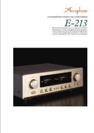
Channel divider units with high-speed DSP for fully digital signal processing<br />
Standard configuration allows 4-channel (4-way) system setup 59<br />
selectable cutoff frequency points Highly accurate 96 dB/oct attenuation slope<br />
Time alignment function allows delay time setting in 0.5-cm steps Delay<br />
compensator offsets signal delays in filter circuitry Further refined MDS++<br />
D/A converter Output mode can be set to monophonic specifications
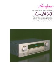
Multi-channel divider with fully digital signal processing – High-speed 40-bit floating<br />
point DSP provides the processing power for four channel units supplied in standard<br />
configuration. Highly accurate digital filters offer a choice of 59 cutoff frequency<br />
points and up to 96 dB/octave attenuation. Integrated time alignment function<br />
adjustable in 0.5-cm steps, and delay compensator for automatically offsetting any<br />
filter circuit delays. Output mode can be changed to monophonic specifications.<br />
Multi-amplification is regarded as the pinnacle of the<br />
audio world. The term refers to dividing the musical<br />
spectrum into several distinct bands and handling<br />
each of these using a dedicated power amplifier and<br />
directly connected speaker unit. Such a system is<br />
necessarily more complex, but when configured and<br />
adjusted properly, it can achieve sound reproduction<br />
on a scale that is not possible by any other means.<br />
Sonic definition and sound quality can be optimized<br />
by the user to obtain exactly the desired result.<br />
Configuring a multi-amplified system affords truly<br />
one of the greatest pleasures of audio.<br />
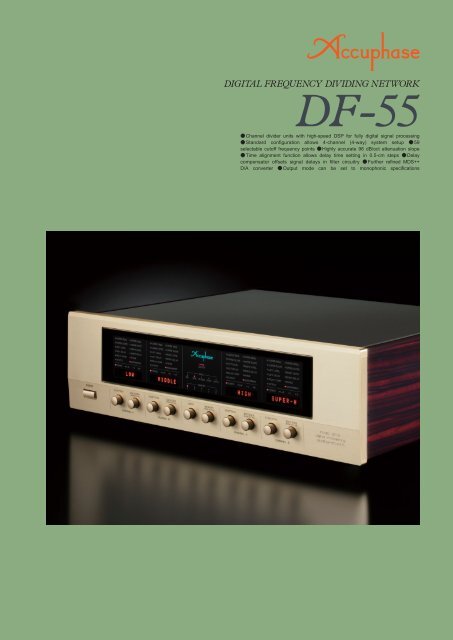
The Digital Frequency Dividing Network <strong>DF</strong>-<strong>55</strong><br />
represents a full model change of the model <strong>DF</strong>-45.<br />
A high-speed, high-precision DSP further minimizes<br />
any calculation errors,<br />
implementing accurate<br />
filtering of the highest<br />
order. Each bandwidth<br />
is handled by a<br />
dedicated divider unit,<br />
and a full array of<br />
High-speed 40-bit floating point<br />
Digital Signal Processor (DSP)<br />
functions including<br />
frequency dividing filters (low-pass, band-pass,<br />
high-pass) with 96 dB/octave attenuation, delay and<br />
delay compensation, level control, and phase<br />
switching are implemented in the digital domain.<br />
Digital as well as analog line and balanced inputs<br />
are provided, and the unit comes as a 4-channel<br />
device (for 4-way amplification) in its standard<br />
configuration.<br />
High-speed, high-precision DSP<br />
implements fully digital signal processing<br />
The <strong>DF</strong>-<strong>55</strong> features high-speed digital signal<br />
processing with amazing power. Latest digital<br />
circuit topology and advanced technology<br />
come together in a filtering DSP that has a<br />
32-bit mantissa and 8-bit exponent section.<br />
The floating point principle enhances<br />
calculation accuracy by dividing numeric<br />
values into mantissa and exponent, thereby<br />
preventing errors even when handling very<br />
small values. This results in dramatically<br />
improved dynamic range and superior<br />
precision, allowing very steep cutoff slope<br />
settings of 48 dB or 96 dB per octave.<br />
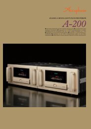
Six filter slope characteristics up to 96 dB<br />
per octave<br />
The filter attenuation characteristics can be set to<br />
6 dB, 12 dB, 18 dB, 24 dB, 48 dB, or 96 dB per<br />
octave. The 96 dB/octave setting in particular<br />
allows the driver unit to reproduce only its<br />
intended frequency without being affected by<br />
adjacent frequency bands. This makes it possible<br />
to create a multi-amped system that takes<br />
musical accuracy to an unprecedented level.<br />
<br />
<br />
<br />
<br />
<br />
<br />
<br />
<br />
<br />
<br />
<br />
HS-Link<br />
<br />
<br />
<br />
<br />
<br />
HS-Link<br />
Receiver<br />
<br />
<br />
Frequency<br />
(Hz)<br />
Fig. 1 Divider Unit Slope Characteristics (Bandpass Filter)<br />
[Cutoff frequency setting 100 Hz for lower and 1 kHz for upper range]<br />
<br />
<br />
<br />
Display<br />
<br />
<br />
<br />
<br />
<br />
Output mode of each divider unit can be set to<br />
STEREO, MONO L+R , MONO L , or MONO R<br />
In normal use, the divider units will be set to<br />
the STEREO position, but by changing the<br />
setting to monophonic (MONO) operation, the<br />
left-channel and right-channel DAC outputs<br />
within the unit are added up, resulting in a<br />
parallel drive configuration that further<br />
reduces residual noise.<br />
Use for a subwoofer (3D) system<br />
Preamplifier<br />
Ultra-low range (monophonic)<br />
<br />
<br />
MONO LR<br />
Cutoff frequency<br />
Low range<br />
STEREO<br />
High range<br />
Channel A Channel B Channel C<br />
<br />
In 3-way system,<br />
channel D is set to<br />
OFF<br />
<strong>DF</strong>-<strong>55</strong><br />
Channel A<br />
In this example, the left and right signals in the ultra-low<br />
frequency range are mixed (channel A output mode is<br />
set to "MONO L+R" position), for configuring a<br />
three-way system with a subwoofer.<br />
2-way system for left and right 2-way monophonic setup<br />
<br />
<br />
<br />
<br />
Cutoff frequency<br />
Low range<br />
Channel A<br />
MONO L<br />
High range<br />
Channel B<br />
Low range<br />
MDS<br />
D/A Conversion System4<br />
Cutoff frequency<br />
Channel C<br />
High range<br />
MONO R<br />
<br />
<strong>DF</strong>-<strong>55</strong><br />
Channel D<br />
Two of the four divider units in the <strong>DF</strong>-<strong>55</strong> are<br />
set to the "MONO L" position and the other<br />
two units to the "MONO R" position. This<br />
allows setting up a 2-way monophonic spec<br />
system.<br />
2-way to 4-way system, using two <strong>DF</strong>-<strong>55</strong> units<br />
The divider units of one <strong>DF</strong>-<strong>55</strong> are set to the "MONO<br />
L" position, and the units of the other <strong>DF</strong>-<strong>55</strong> to the<br />
"MONO R" position. This allows setting up a 2-way<br />
to 4-way monophonic spec multi-amped system.<br />
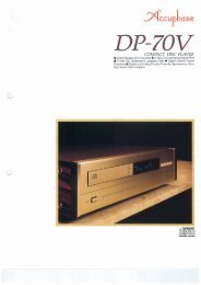
Time alignment function allows delay<br />
adjustment in 0.5-cm steps<br />
The sound emanating from a speaker travels through the<br />
air at a speed of about 343.5 meters per second (when<br />
the ambient temperature is 20 degrees centigrade).<br />
Compared to the propagation speed of light or of electrical<br />
signals, this is extremely slow. When multiple speaker<br />
units are used, necessarily located at different positions,<br />
there will be differences in the time required for the sound<br />
to reach the ear of the listener. In a multi-speaker system,<br />
each sound source position, namely the position of the<br />
diaphragm in the respective driver unit, is not aligned on<br />
the front/back plane, also leading to different arrival times<br />
of the sound. Compensating for such differences is called<br />
time alignment (see Figure 3). The <strong>DF</strong>-<strong>55</strong> incorporates<br />
a DELAY function that uses digital signal processing to<br />
electrically adjust the time when the sound from each<br />
driver reaches the listener. Normally, a delay would be<br />
expressed as a time value, but since the delay here is<br />
caused by spatial distance, the <strong>DF</strong>-<strong>55</strong> converts the delay<br />
into a distance value (cm) for easier understanding.<br />
Lin<br />
Assembly with<br />
high-speed DSP chip<br />
59 selectable cutoff frequency points<br />
Filter frequency points can be set over the range<br />
from 31.5 Hz to 22.4 kHz in 1/6-octave intervals. In<br />
addition, 10, 20, and 290 Hz points are also<br />
provided, resulting in a total of 59 points. Each<br />
divider unit is fully flexible and allows free selection<br />
of the lower and upper cutoff frequency.<br />
Digital<br />
Inputs<br />
Analog<br />
Inputs<br />
Digital<br />
Output<br />
Coaxial<br />
Optical<br />
Balanced<br />
Line<br />
Hs-Link<br />
Coaxial<br />
Receiver<br />
Optical<br />
Receiver<br />
A/D<br />
Converter<br />
A/D<br />
Converter<br />
Hs-Link<br />
Transceiver<br />
Encoder<br />
DAI<br />
Decoder<br />
Fig. 2 <strong>DF</strong>-<strong>55</strong> Block Diagram<br />
Micro-<br />
Computer<br />
Date/Clock<br />
Distributor<br />
DSPDigital Signal Processor<br />
Frequency<br />
Phase<br />
Delay<br />
Output<br />
Channel B<br />
Channel C<br />
Channel D<br />
Floating Point<br />
DSP<br />
Master Level<br />
Coefficient<br />
Memory<br />
Level<br />
Slope<br />
Delay Comp<br />
Digital Filter<br />
DAC<br />
MDS<br />
D/A Conversion System4<br />
Digital Filter<br />
DAC<br />
Same as Channel A<br />
Same as Channel A<br />
Same as Channel A<br />
Analog<br />
Attenuator<br />
ON/OFF<br />
Analog<br />
Attenuator<br />
ON/OFF<br />
Mono<br />
ON/OFF<br />
Buffer<br />
Buffer<br />
Buffer<br />
Buffer<br />
Balan<br />
Lin<br />
Balan
Input<br />
Time alignment using delay<br />
Delay<br />
d cm<br />
Speaker unit and L sound H source<br />
(diaphragm) are d centimeters apart<br />
H<br />
L<br />
t seconds<br />
H<br />
Delay<br />
Start time<br />
t seconds<br />
Fig. 3 Time Alignment Principle<br />
Delay function<br />
delays waveform<br />
H<br />
by t seconds<br />
e Time<br />
Delay ensures that and L signals H<br />
arrive at the ear at the same time<br />
Speed of sound = 331.5 + 0.607 T [m/sec] T: temperature (°C)<br />
Consequently, at 20°C, sound travels at about 343.5 m/sec.<br />
In the example above, when DELAY function for H is set to d cm, the<br />
signal start for H will be delayed by t = d/34,350 seconds, causing the<br />
sound from L and H to reach the listener at the same time.<br />
L<br />
High-performance Hyperstream TM DAC used for MDS++<br />
MDS (Multiple Delta Sigma) is a revolutionary design which<br />
employs several delta sigma type converters in a parallel<br />
configuration. In the combined output of these multiple<br />
converters, the ratio of conversion errors to the audio signal<br />
becomes larger, resulting in a drastic improvement in all<br />
relevant aspects of converter performance, such as accuracy,<br />
S/N ratio, dynamic range, linearity, and THD. (When the<br />
number of converters is taken as "n", the improvement is n.)<br />
Because the performance improvement afforded by the MDS<br />
principle is not dependent on signal frequency or signal level,<br />
noise at very low levels that<br />
plagues the output of<br />
conventional converters can<br />
also be reliably reduced.<br />
In the <strong>DF</strong>-<strong>55</strong>, four Hyperstream TM<br />
DAC chips (ES9008 made by<br />
ESS Technology) of the latest<br />
generation are driven in parallel. Compared to a single<br />
converter, this results in an overall performance improvement<br />
by a factor of 2 (= 4). As shown in the diagram, the MDS++<br />
circuit features an enhanced current-to-voltage (I/V) converter<br />
for processing the D/A converter output current. A combination<br />
of current summing and voltage summing is used, for optimized<br />
operation.<br />
The overall result is improved stability and top-notch<br />
performance. The music emerges from a totally silent<br />
background, with breathtaking detail resolution and accurate<br />
spatial information.<br />
(Normal phase output)<br />
<br />
(Reverse phase output)<br />
<br />
<br />
<br />
(current)(voltage)<br />
converter<br />
<br />
<br />
<br />
<br />
Current summing<br />
Voltage summing<br />
Block diagram ofMDS++ converter<br />
<br />
<br />
Subtraction<br />
DAC output<br />
Other Functions and Features<br />
<br />
<br />
"Analog ATT" function can be activated for specific channels to reduce residual noise when<br />
using high-efficiency midrange or high range speaker units (ON: -10 dB).<br />
Versatile choice of input connectors. Digital signals can be supplied via coaxial, optical,<br />
and HS-Link inputs. Line and balanced inputs are available for analog signals.<br />
"Full Level Output Protection" function safeguards the speakers if a digital signal<br />
without volume control data is input (Output level reduction -40 dB).<br />
Unused divider units can be set to OFF (all display elements and LED<br />
indicators are out).<br />
Safety Lock prevents inadvertently changing any settings.<br />
Display indication can show predefined strings or custom strings<br />
entered by the user (max. 8 characters, character set 97<br />
characters).<br />
ndependent phase switching for left and<br />
right channel (4 patterns).<br />
The <strong>DF</strong>-<strong>55</strong> comes standard with four units named CHANNEL A - D<br />
(4-way configuration). The assembly shown here carries the<br />
coaxialdigital input and output connectors, line/analog input<br />
connectors, MDS++ D/A converter modules for<br />
4 channels, and line/analog output<br />
connectors.<br />
e<br />
Left<br />
Analog<br />
Outputs<br />
ced<br />
e<br />
Right<br />
Analog<br />
Outputs<br />
ced
Delay compensator function of <strong>DF</strong>-<strong>55</strong> (providing automatic compensation for signal delays)<br />
Besides delays caused by speaker placement,<br />
a certain delay will also occur when a signal<br />
passes through a filter circuit. The <strong>DF</strong>-<strong>55</strong><br />
incorporates a function called "DELAY COMP"<br />
that compensates for such delays. As an<br />
example, the illustration at right shows a<br />
simplified representation of how the delay<br />
compensator function works in a 3-way system.<br />
Regardless of whether a circuit is analog or<br />
digital, when the signal has to pass through a<br />
filter, the output will be delayed by a certain<br />
amount, causing a delay in step response<br />
and impulse response.<br />
Generally, a low-pass filter will have more<br />
delay. The <strong>DF</strong>-<strong>55</strong> therefore only provides<br />
compensation when low-pass filtering is<br />
used.<br />
The lower the filter frequency and the steeper<br />
the filter slope, the longer the delay.<br />
ON<br />
OFF<br />
The <strong>DF</strong>-<strong>55</strong> calculates and displays the<br />
theoretical delay time, and automatically<br />
provides compensation. (Default setting)<br />
The <strong>DF</strong>-<strong>55</strong> calculates and displays the<br />
theoretical delay time for reference, and the<br />
user can manually set any desired value.<br />
Operation principle of delay compensator<br />
Input<br />
Channel A<br />
Delay: t 3 s<br />
(Low-pass filter)<br />
Channel B<br />
Delay: t 2 s<br />
(Band-pass filter)<br />
Channel C<br />
Delay: 0 s<br />
(High-pass filter)<br />
As shown above, the signal<br />
will be delayed by a different<br />
duration when passing<br />
through different filter circuits.<br />
DELAY COMP<br />
function<br />
<br />
<br />
<br />
Outputa<br />
Outputb<br />
Outputc<br />
When DELAY COMP is OFF, the output<br />
signals in each channel will be shifted,<br />
causing time misalignment. Output<br />
signal vs input signal time lag (delay)<br />
Time lag (delay) of output signal with<br />
regard to input in each channel<br />
When OFF:<br />
is a slowest, delayed<br />
by t3 seconds versus c<br />
is b delayed<br />
by t2 seconds<br />
versus c<br />
OFF<br />
<br />
OFF<br />
<br />
When ON:<br />
Delayed by<br />
t3 - t2 seconds<br />
<br />
When ON: Delayed by t3 seconds<br />
ON or OFF<br />
ON<br />
ON<br />
When DELAY COMP is<br />
ON, the time difference<br />
between output signals , a<br />
, b and <br />
c<br />
When DELAY COMP is ON<br />
and b are c delayed, using<br />
slowest as a reference 0<br />
<br />
Channel A<br />
is delayed by [t3 - t2] seconds<br />
<br />
Channel B<br />
is delayed by t3 seconds<br />
<br />
Channel C<br />
(compensation a<br />
time)<br />
(compensation b<br />
time)<br />
(compensation c<br />
time)<br />
Actual delay compensator<br />
indication is in cm, converted<br />
from the above compensation<br />
time value.<br />
<strong>DF</strong>-<strong>55</strong> default settings and display indication<br />
LOWER FREQUENCY<br />
LOWER SLOPE<br />
LEFT LEVEL<br />
LEFT DELAYcm<br />
DELAY COMP<br />
OUTPUT<br />
STEREO<br />
Front panel<br />
Rear panel<br />
Function <br />
UPPER FREQUENCY<br />
UPPER SLOPE<br />
RIGHT LEVEL<br />
RIGHT DELAYcm<br />
PHASE<br />
ASSIGNMENT<br />
q POWER switch<br />
w FUNCTION knob (To select a function)<br />
e ENCODER knob (To set the value)<br />
r Input selector<br />
t Memory selector<br />
y Display<br />
INPUT: BAL, LINE, HS-LINK, COAX, OPTO<br />
MEMORY: 1, 2, 3, 4, 5<br />
Display indication<br />
* ( ) symbol at top right of level indication is shown when "Full Level Output Protection" function is set to ON.<br />
q<br />
u<br />
i<br />
w e<br />
o<br />
Divider units<br />
Channel A Channel B Channel C Channel D<br />
Channel<br />
D<br />
r<br />
t y<br />
Analog outputs<br />
LINE/BALANCED<br />
Channel<br />
C<br />
Channel<br />
B<br />
Channel<br />
A<br />
!0<br />
u Digital inputs<br />
HS-LINK,COAXIAL,OPTICAL<br />
i Digital output<br />
HS-LINK<br />
o Analog inputs<br />
LINE, BALANCED<br />
!0 AC power connector <br />
(for supplied power cord)<br />
<br />
Cutoff frequency settings (Hz)<br />
10 20 31.5 35.5 40 45 50 56 63 71 80 90<br />
100 112 125 140 160 180 200 224 250 280 290 315<br />
3<strong>55</strong> 400 500 560 630 710 800 900 1000 1120 1250 1400<br />
1600 1800 2000 2240 2500 2800 3150 3<strong>55</strong>0 4000 5000 5600 6300<br />
7100 8000 9000 10k 11.2k 12.5k 14k 16k 18k 20k 22.4k<br />
<strong>DF</strong>-<strong>55</strong> Guaranteed Specifications<br />
[Guaranteed specifications measured in compliance with JEITA standard method CP-2402A]<br />
Digital inputs<br />
COAXIAL Format: IEC 60958/AES3 compliant<br />
Sampling frequencies 32 kHz to 192 kHz (16 - 24 bit 2-channel PCM)<br />
OPTICAL Format: JEITA CP-1212<br />
Sampling frequencies 32 kHz to 96 kHz (16 - 24 bit 2-channel PCM)<br />
HS-LINK Connector: RJ-45, HS-Link cable<br />
Sampling frequencies 32 kHz to 192 kHz (24 bit 2-channel PCM)<br />
Analog inputs Maximum input level 3.7 V (1 kHz, 2.5 V output)<br />
A/D converter Principle: 1-bit delta sigma modulation<br />
Sampling frequency: 176.4 kHz<br />
Quantization: 24 bit<br />
Digital outputs HS-LINK Connector: RJ-45, HS-Link cable<br />
COAXIAL Format: IEC 60958<br />
Frequency response HS-Link2.0 - 50,000 Hz +0 -3 dB<br />
D/A converter Quantization: 24 bit<br />
STEREO operation: 4MDS++ type<br />
MONO operation: 8MDS++ type<br />
THD<br />
0.001% (20 - 20,000 Hz)<br />
S/N ratio<br />
COAXIAL/OPTICAL<br />
HS-LINK<br />
Analog input<br />
(Cutoff characteristics: -3.0 dB, 59 points)<br />
STEREO operation<br />
120 dB<br />
120 dB<br />
113 dB<br />
MONO operation<br />
122 dB<br />
122 dB<br />
114 dB<br />
Dynamic range "Analog ATT" OFF: 117 dB, "Analog ATT" ON: 114 dB<br />
Channel separation 108 dB (20 - 20,000 Hz)<br />
Slope characteristics 6 dB/octave, 12 dB/octave, 18 dB/octave<br />
24 dB/octave, 48 dB/octave, 96 dB/octave<br />
* When cutoff frequency is 10 Hz: 48 dB/octave, 96 dB/octave not available<br />
20 Hz: 96 dB/octave not available<br />
Delay setting range -3,000 to +3,000 cm (0.5-cm steps)<br />
(converted into distance)<br />
Level adjustment range "Analog ATT" OFF: -40 to +12.0 dB (0.1-dB steps)<br />
"Analog ATT" ON: -50 to +2.0 dB (0.1-dB steps)<br />
Output voltage/output LINE: 2.5 V, 50 ohms, RCA-type phono connector<br />
impedance<br />
BALANCED: 2.5 V, 50 ohms, balanced XLR connector<br />
Minimum loadimpedance LINE/BALANCED 600 ohms<br />
Power requirements AC 120 V/230 V, 50/60 Hz (Voltage as indicated on rear panel)<br />
Power consumption 29 watts<br />
Max. dimensions Width 465 mm (18-5/16")<br />
Height 151 mm (5-15/16")<br />
Depth 396 mm (15-9/16")<br />
Mass<br />
14.7 kg (32.4 lbs) net<br />
20.0 kg (44.1 lbs) in shipping carton<br />
Remarks<br />
This product is available in versions for 120/230 V AC. Make sure that the voltage shown on the rear panel matches the AC line voltage in your area.<br />
The shape of the AC inlet and plug of the supplied power cord depends on the voltage rating and destination country.<br />
Supplied accessory<br />
AC power cord<br />
Specifications and design subject to change without notice for improvements.<br />
A1105YPRINTED IN JAPAN851-0202-00B1