PVSR-E volume flow controller_rectangular - Pichler
PVSR-E volume flow controller_rectangular - Pichler
PVSR-E volume flow controller_rectangular - Pichler

You also want an ePaper? Increase the reach of your titles
YUMPU automatically turns print PDFs into web optimized ePapers that Google loves.
VOLUME FLOW CONTROLLER IN RECTANGULAR VERSION <strong>PVSR</strong>-E PAGE 25<br />
6,4.3 MP bus mode VAV / CAV function<br />
only with MP bus compact regulator<br />
VAV compact regulators can be actuated<br />
conventionally or via MP bus. Integration<br />
into LONWORKS®, EIB / KNX or DDC<br />
systems with MP interface can therefore<br />
be implemented easily and costeffectively.<br />
The VAV compact regulator can be<br />
connected via integrated communication<br />
with up to 8 MP devices (valve adjusting,<br />
valve drives, VAV compact regulator, via<br />
MP bus.<br />
These slave devices receive their control<br />
signal digitally from the higher level bus<br />
master via the MP bus and move to the<br />
set position.<br />
Due to the allocation of an MP address,<br />
the standard VAV compact regulator to<br />
the bus-compatible system regulator<br />
with a wide variety of additional uses.<br />
In bus mode, the VAV compact regulator<br />
receives its control signal via the MP<br />
bus from the higher level building<br />
automation system and is regulated to<br />
the specified <strong>volume</strong> <strong>flow</strong>.<br />
The changeover to MP bus mode is<br />
carried out automatically once the VAV<br />
compact regulator is assigned an MP<br />
address. An active or passive sensor or<br />
switch can be connected to every VAV<br />
compact drive. This input value can be<br />
used in the higher level system, e.g. for<br />
the VAV control, room temperature or<br />
other applications.<br />
The connection to the MP bus is carried<br />
out via the connection cable fitted on the<br />
VAV compact drive.<br />
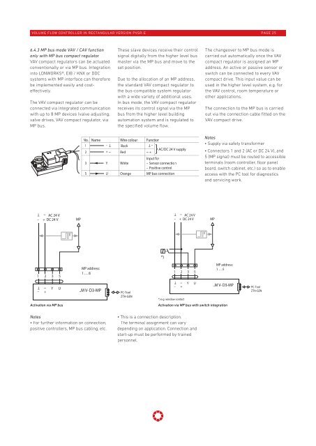
No. Name Wire colour Function<br />
1<br />
Black<br />
AC/DC 24 V supply<br />
2 + ~ Red ~ +<br />
T –<br />
3 Y White<br />
– T<br />
Input for<br />
– Sensor connection<br />
– Positive control<br />
5 U Orange MP bus connection<br />
Notes<br />
• Supply via safety transformer<br />
• Connectors 1 and 2 (AC or DC 24 V), and<br />
5 (MP signal) must be routed to accessible<br />
terminals (room <strong>controller</strong>, floor panel<br />
board, switch cabinet, etc.) so as to enable<br />
access with the PC tool for diagnostics<br />
and servicing work.<br />
AC 24 V<br />
– + DC 24 V<br />
T<br />
~<br />
MP<br />
AC 24 V<br />
– + DC 24 V<br />
T<br />
~<br />
MP<br />
*)<br />
1 2 3 5<br />
MP address:<br />
1 … 8<br />
1 2 3 5<br />
MP address:<br />
1 … 8<br />
~ T<br />
_<br />
+<br />
Y<br />
U<br />
..M V- D3-MP<br />
PC-Tool<br />
ZTH-GEN<br />
~ T<br />
_<br />
+<br />
*) e.g. window contact<br />
Y<br />
U<br />
..M V- D3-MP<br />
PC-Tool<br />
ZTH-GEN<br />
Activation via MP bus<br />
Activation via MP bus with switch integration<br />
Notes<br />
• For further information on connection,<br />
positive <strong>controller</strong>s, MP bus cabling, etc.<br />
• This is a connection description.<br />
The terminal assignment can vary<br />
depending on application. Connection and<br />
start-up must be performed by trained<br />
personnel.