Taurus ELECTRO manual 472 ENG.pdf - Pipistrel
Taurus ELECTRO manual 472 ENG.pdf - Pipistrel
Taurus ELECTRO manual 472 ENG.pdf - Pipistrel

Create successful ePaper yourself
Turn your PDF publications into a flip-book with our unique Google optimized e-Paper software.
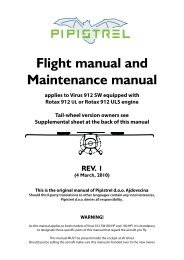
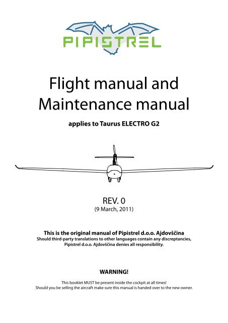
Flight <strong>manual</strong> and<br />
Maintenance <strong>manual</strong><br />
applies to <strong>Taurus</strong> <strong>ELECTRO</strong> G2<br />
REV. 0<br />
(9 March, 2011)<br />
This is the original <strong>manual</strong> of <strong>Pipistrel</strong> d.o.o. Ajdovščina<br />
Should third-party translations to other languages contain any discreptancies,<br />
<strong>Pipistrel</strong> d.o.o. Ajdovščina denies all responsibility.<br />
WARNING!<br />
This booklet MUST be present inside the cockpit at all times!<br />
Should you be selling the aircraft make sure this <strong>manual</strong> is handed over to the new owner.
2 TAURUS <strong>ELECTRO</strong> www.pipistrel.si<br />
REV. 0<br />
<strong>Taurus</strong> model:<br />
Factory serial number:<br />
Date of manufacture:<br />
Aircraft empty weight (kg):<br />
Available crew weight (no front ballast):<br />
Available crew weight (9 kg front ballast):<br />
Available luggage weight:<br />
List of equipment included in aircraft empty weight:<br />
Date and place of issue: Ajdovščina,<br />
To log into the Owner’s section, receive updates and Service Bulletins, go to: www.pipistrel.si and log in<br />
the top right corner of the page with:<br />
Username: owner1<br />
Password: ab2008<br />
THANK YOU!
www.pipistrel.si<br />
TAURUS <strong>ELECTRO</strong> 3<br />
REV. 0<br />
<strong>Pipistrel</strong> d.o.o. Ajdovščina, Goriška cesta 50a, SI- 5270 Ajdovščina, Slovenija<br />
tel: +386 (0)5 3663 873, fax: +386 (0)5 3661 263, e-mail: info@pipistrel.si<br />
www.pipistrel.si<br />
Flight <strong>manual</strong> and<br />
Maintenance <strong>manual</strong> for<br />
<strong>Taurus</strong> <strong>ELECTRO</strong><br />
Model: <strong>Taurus</strong> <strong>ELECTRO</strong><br />
Data Sheet:<br />
Factory serial number:<br />
Registration number:<br />
Date of Issue: March, 2011<br />
Pages signed under “Approval” in section Index of revisions and List of valid pages<br />
(pages 4 and 5 of this <strong>manual</strong>) are approved by:<br />
Authority: SLO.DOA.002<br />
Signature:<br />
Stamp:<br />
Original date of Approval: March, 2011<br />
This aircraft is to be operated in compliance with information and limitations contained herein.<br />
The original English Language edition of this <strong>manual</strong> has been approved as operating instruction<br />
according to “Pravilnik o ultralahkih letalnih napravah” of Republic of Slovenia.<br />
Approval of translation has been done by best knowledge and judgement.
4 TAURUS <strong>ELECTRO</strong> www.pipistrel.si<br />
REV. 0<br />
Index of revisions<br />
Enter and sign the list of revised pages in the <strong>manual</strong> into the spaces provided below. All revised pages<br />
should be clearly designated in the upper right corner of the page, also, any changes in page content<br />
should be clearly visible (e.g. marked with a bold black vertical line).<br />
Name of<br />
revision<br />
Reason for<br />
Revision:<br />
Revision no.,<br />
date:<br />
Description:<br />
Affected<br />
pages:<br />
Approval,<br />
signature:<br />
Original /<br />
Rev. 0<br />
9 March, 2011<br />
First original release. / Tomazic
www.pipistrel.si<br />
TAURUS <strong>ELECTRO</strong> 5<br />
REV. 0<br />
List of valid pages<br />
This <strong>manual</strong> contains 96 original and revised pages listed below.<br />
Pages<br />
State<br />
(Revision)<br />
Cover REV. 0<br />
Page numbering REV. 0<br />
Authority approval sheet 3 REV. 0<br />
Index of revisions 4 REV. 0<br />
List of valid pages 5 REV. 0<br />
Table of contents 7 REV. 0<br />
General 9 - 12 REV. 0<br />
Limitations 13 - 20 REV. 0<br />
Emergency procedures 21 - 28 REV. 0<br />
Normal procedures 29 - 42 REV. 0<br />
Performance 43 - 51 REV. 0<br />
Weight and balance 53 - 59 REV. 0<br />
Aircraft and systems on board 61 - 73 REV. 0<br />
Handling and maintenance 75 - 84 REV. 0<br />
Appendix 85 - 93 REV. 0<br />
Approval:<br />
CAUTION!<br />
This <strong>manual</strong> is valid only if it contains all of the original and revised pages listed above.
6 TAURUS <strong>ELECTRO</strong> www.pipistrel.si<br />
REV. 0<br />
This page is intentionally left blank.
www.pipistrel.si<br />
TAURUS <strong>ELECTRO</strong> 7<br />
REV. 0<br />
Table of contents<br />
General<br />
Limitations<br />
Emergency procedures<br />
Normal procedures<br />
Performance<br />
Weight and balance<br />
Aircraft and systems on board<br />
Handling and maintenance<br />
Appendix
8 TAURUS <strong>ELECTRO</strong> www.pipistrel.si<br />
REV. 0<br />
This page is intentionally left blank.
www.pipistrel.si<br />
TAURUS <strong>ELECTRO</strong> 9<br />
General<br />
REV. 0<br />
General<br />
Introduction<br />
Notes and remarks<br />
Technical data<br />
3-view drawing
10 TAURUS <strong>ELECTRO</strong> www.pipistrel.si<br />
General<br />
REV. 0<br />
Introduction<br />
This <strong>manual</strong> contains all information needed<br />
for appropriate and safe use of <strong>Taurus</strong> Electro<br />
IT IS MANDATORY TO CAREFULLY<br />
STUDY THIS MANUAL PRIOR TO USE<br />
OF AIRCRAFT<br />
In case of aircraft damage or people injury<br />
resulting form disobeying instructions in the<br />
<strong>manual</strong> PIPISTREL d.o.o. Ajdovscina denies all<br />
responsibility.<br />
All text, design, layout and graphics are<br />
owned by PIPISTREL d.o.o. Ajdovscina<br />
Therefore this <strong>manual</strong> and any of its contents<br />
may not be copied or distributed in any manner<br />
(electronic, web or printed) without the<br />
prior consent of PIPISTREL d.o.o. Ajdovscina<br />
Notes and remarks<br />
Safety definitions used in the <strong>manual</strong>:<br />
WARNING! Disregarding the following instructions WILL LEAD to severe<br />
deterioration of flight safety and hazardous situations, including such<br />
resulting in injury and loss of life.<br />
CAUTION! Disregarding the following instructions WILL LEAD to serious<br />
deterioration of flight safety.<br />
Technical data<br />
PROPORTIONS<br />
<strong>ELECTRO</strong><br />
wing span<br />
14.97 m<br />
length<br />
7.30 m<br />
height (propeller extended)<br />
2.7 m<br />
wing area 12.26 m 2<br />
vertical tail area 0.86 m 2<br />
horizontal stabilizer and elevator area 1.275 m 2<br />
aspect ratio 18.30<br />
positive flap deflection (down) 5°, 9 °, 18 °<br />
negative flap deflection (up) -5°<br />
centre of gravity (% of MAC) 23% - 45%
www.pipistrel.si<br />
3-view drawing<br />
TAURUS <strong>ELECTRO</strong> 11<br />
General<br />
REV. 0<br />
2700<br />
7300<br />
4403
12 TAURUS <strong>ELECTRO</strong> www.pipistrel.si<br />
REV. 0<br />
This page is intentionally left blank.
www.pipistrel.si<br />
TAURUS <strong>ELECTRO</strong> 13<br />
Limitarions<br />
REV. 0<br />
Limitations<br />
Introduction<br />
Operational velocities<br />
Motor, fuel, oil<br />
Weight limits<br />
Centre of gravity limits<br />
Manoeuvre limits<br />
G-load factors<br />
Cockpit crew<br />
Types of operations<br />
Minimum equipment list<br />
Other restrictions<br />
Warning placards
14 TAURUS <strong>ELECTRO</strong> www.pipistrel.si<br />
Limitations<br />
REV. 0<br />
Introduction<br />
This chapter provides information about operational restrictions, instrument markings and basic<br />
knowledge on safe operation of aircraft, motor and on-board appliances.<br />
Operational velocities<br />
Speed limits<br />
VNE<br />
VPE<br />
VPO<br />
VRA<br />
Velocity<br />
IAS<br />
[km/h (kts)]<br />
Velocity never to be<br />
exceeded 225 (121)<br />
Max. speed with<br />
powerplant extended 120 (65)<br />
Max. speed to extend<br />
or retract powerplant 100 (54)<br />
Maximum safe velocity<br />
in rough air 163 (88)<br />
VA Manoeuvering velocity 163 (88)<br />
VFE<br />
VAE<br />
Max. velocity flaps<br />
extended 130 (70)<br />
Max. velocity of<br />
airbrake extention 163 (88)<br />
VLO Max ldg. down speed 163 (88)<br />
Remarks<br />
Never exceed this speed. Should the VNE be<br />
exceeded, land as soon as possible and have<br />
the aircraft verified for airworthiness by authorised<br />
service personnel.<br />
Do not exceed this speed with powerplant<br />
extended.<br />
Do not extend or retract powerplant above<br />
this speed.<br />
Also known as Vb. Turbulence penetration<br />
speed.<br />
Do not use rough or full stick and<br />
rudder deflecions above this speed.<br />
Do not exceed this speed with +5° or T flaps<br />
extended. (VFE for L flaps is 110 km/h (59 kts))<br />
Do not extend spoilers above this<br />
speed. Once fully extended, VNE is the limit.<br />
Do not fly with landing gear extended<br />
above this speed<br />
Airspeed indicator markings<br />
MARKING IAS [km/h (kts)] Definition<br />
white arc<br />
69 - 130<br />
(37 - 70)<br />
green arc<br />
78 - 163<br />
(42 - 88)<br />
yellow arc<br />
163 - 225<br />
(88 - 121)<br />
225<br />
red line Maximum speed allowed.<br />
(121)<br />
blue line 100 (54) Best climb rate speed (V Y<br />
)<br />
Speed range where flaps may be extended. Lower end is defined<br />
as 110% of VS (stall speed in landing configuration at<br />
MTOM), upper end of speed range is limited by VFE<br />
(see above).<br />
Speed range of normal operation. Lower end is defined as<br />
110% of VS1 (stall speed at MTOM with flaps in neutral position),<br />
upper end is limited by VRA (see above).<br />
Manouvre the aircraft with great caution in calm air only.<br />
WARNING! Above pressure altitude of 1000 meters (3300 ft) all speed limits<br />
MUST be treated as True AirSpeed (TAS).<br />
Indicated AirSpeed (IAS) MUST be reduced accordingly!
www.pipistrel.si<br />
TAURUS <strong>ELECTRO</strong> 15<br />
Limitations<br />
REV. 0<br />
Indicated airspeed (IAS) to true airspeed (TAS) relation<br />
Airspeed indicator measures the difference between total and static pressure (also called dynamic<br />
pressure), which does not only change as speed increases, but is also linked with altitude. Flying at<br />
high altitudes, where the air is getting thinner, results in misinterpreting airspeed which is being<br />
indicated. The indicated airspeed value is actually lower than the true airspeed to which the aircraft<br />
is exposed. The higher you fly, the bigger the difference between IAS and TAS. Be aware of this effect<br />
especially when flying at high altitude at high speeds, not to exceed VNE unawarely. Bear in mind<br />
this can happen even with the indicator still pointing within the yellow arc!<br />
VNE at altitude (standard ICAO atmosphere)<br />
The tables below indicate IAS to TAS relation for an altitude span of 0 - 5000m (0 - FL165) in different<br />
atmospheres (variable is temperature). TAS is a constant of 225 km/h (122 kts) - VNE for the entire tables.<br />
ISA-20 (-5°C at sea level):<br />
Altitude (meters) 0 500 1000 1500 2000 2500 3000 3500 4000 4500 5000<br />
Altitude (flight level) 0 FL16 FL33 FL50 FL66 FL82 FL98 FL115 FL131 FL148 FL165<br />
VNE IAS (km/h) 225 225 223 218 213 209 203 198 194 189 185<br />
VNE IAS (kts) 121 121 120 118 115 113 110 107 105 102 100<br />
ISA-10 (5°C at sea level):<br />
Altitude (meters) 0 500 1000 1500 2000 2500 3000 3500 4000 4500 5000<br />
Altitude (flight level) 0 FL16 FL33 FL50 FL66 FL82 FL98 FL115 FL131 FL148 FL165<br />
VNE IAS (km/h) 225 224 219 214 209 205 199 195 191 186 182<br />
VNE IAS (kts) 121 121 118 116 113 111 108 105 103 100 98<br />
ISA (15°C at sea level):<br />
Altitude (meters) 0 500 1000 1500 2000 2500 3000 3500 4000 4500 5000<br />
Altitude (flight level) 0 FL16 FL33 FL50 FL66 FL82 FL98 FL115 FL131 FL148 FL165<br />
VNE IAS (km/h) 225 220 215 210 205 201 196 191 187 182 178<br />
VNE IAS (kts) 121 119 116 113 111 109 106 103 101 98 96<br />
ISA+10 (25°C at sea level):<br />
Altitude (meters) 0 500 1000 1500 2000 2500 3000 3500 4000 4500 5000<br />
Altitude (flight level) 0 FL16 FL33 FL50 FL66 FL82 FL98 FL115 FL131 FL148 FL165<br />
VNE IAS (km/h) 220 215 211 206 202 197 192 188 184 179 175<br />
VNE IAS (kts) 119 116 114 111 109 106 104 102 99 97 94<br />
ISA+20 (35°C at sea level) :<br />
Altitude (meters) 0 500 1000 1500 2000 2500 3000 3500 4000 4500 5000<br />
Altitude (flight level) 0 FL16 FL33 FL50 FL66 FL82 FL98 FL115 FL131 FL148 FL165<br />
VNE IAS (km/h) 216 211 207 202 197 193 189 184 180 175 171<br />
VNE IAS (kts) 117 114 112 109 106 104 102 99 97 94 92<br />
Note how VNE decreases at higher altitudes!<br />
WARNING! Respect the Listed values at all times, not to exceed flutter critical<br />
speed.
16 TAURUS <strong>ELECTRO</strong> www.pipistrel.si<br />
REV. 0 Limitations<br />
Motor/controller, Battery System<br />
Motor types: <strong>ELECTRO</strong>40/30<br />
WARNING! The motor is not certified for aviation use, therefore, there is no assurance<br />
it cannot fail in its operation at any given moment, without prior notice.<br />
The motor<br />
TEMPERATURE °C / <strong>ELECTRO</strong>MOTOR <strong>ELECTRO</strong> 40/30<br />
maximum take-off power (1 min)<br />
40 kW<br />
maximum continous power<br />
30 kW<br />
maximum operating temperature<br />
100° C<br />
maximum ambient temperature<br />
40° C<br />
RPM <strong>ELECTRO</strong> 40/30<br />
maximum allowable 2200<br />
take-off rpm (typical) 2150<br />
climb rpm (typical) 1900<br />
Controller<br />
POWER CONTROLLER <strong>ELECTRO</strong> 40/30<br />
maximum operating temperature<br />
75° C<br />
recommended max continous temperature<br />
45-55° C<br />
WARNING! DO NOT, UNDER ANY CIRCUMSTANCES, ATTEMPT TO USE ANY OTHER<br />
BATTERIES, OTHER THAN PIPISTREL FACTORY ORIGINAL BATTERY SYSTEM, WITH THIS MOTOR/<br />
CONTROLLER<br />
Battery system<br />
Battery system<br />
Maximum voltage<br />
Minimum voltage<br />
Recommended voltage range for storage<br />
Maximum operating temperature<br />
Minimum operating temperature<br />
Allowable temperature range for storage<br />
Standard<br />
270 V<br />
190 V<br />
230 V - 250 V<br />
70° C<br />
5° C<br />
10°C - 40° C<br />
CAUTION! TEMPERATURES BELOW 10°C WILL RESULT IN DECREASE OF BATTERY CAPACITY.<br />
PLAN YOUR FLIGHT ACCORDINGLY.<br />
WARNING! DO NOT, UNDER ANY CIRCUMSTANCES, ATTEMPT TO CHARGE THE BATTERIES<br />
WITH ANY THIRD PARTY CHARGERS. ONLY PIPISTREL ORIGINAL EQUIPMENT MUST BE USED.<br />
WARNING! RESPECT OPERATING AND STORAGE TEMPERATURE LIMITS AT ALL TIMES.<br />
FAILURE TO DO SO MAY RESULT IN BATTERY DAMAGE.
www.pipistrel.si<br />
TAURUS <strong>ELECTRO</strong> 17<br />
Limitations<br />
REV. 0<br />
Propeller<br />
TAURUS<br />
fixed pitch (wooden or composite)<br />
<strong>ELECTRO</strong><br />
1650mm<br />
Motor instrument markings<br />
WARNING! User IS TO Fill in motor specific values.<br />
Instrument<br />
Tachometer (RPM)<br />
Red line<br />
(minimum)<br />
/<br />
Green arc<br />
(normal)<br />
0-2150<br />
Yellow arc<br />
(caution)<br />
2150-2200<br />
Red line<br />
(maximum)<br />
2200<br />
Controller temp. (°C)<br />
/<br />
5-55<br />
55-70<br />
70<br />
Battery system temp (°C)<br />
5<br />
10-50<br />
50-70<br />
70<br />
Weight limits<br />
<strong>Taurus</strong> electro basic model weights<br />
WEIGHT<br />
<strong>ELECTRO</strong><br />
empty aircraft weight (incl. parachute rescue system), std battery system<br />
306 kg<br />
empty aircraft weight (incl. parachute rescue system), optional batteries sys. 323 kg<br />
max. takeoff weight (MTOW/MTOM)<br />
550 kg<br />
minimum combined cockpit crew weight (depends on C.G. of empty aircraft) see p. 55<br />
maximum combined cockpit crew weight (depends on C.G. of empty aircraft) see p. 55<br />
water ballance reservoir (max weight)<br />
9 kg<br />
allowable luggage weight<br />
10 kg<br />
WARNING! Should one of the above-listed values be exceeded, others MUST be<br />
reduced in order to keep MTOM below 550 kg. mAKE SURE Maximum AND MINIMUM<br />
COCKPIT CREW WEIGHT AS WELL AS AVAILABLE LUGGAGE WEIGHT ARE ALWAYS KEPT WITHIN<br />
ALLOWABLE LIMITS. fAILING TO COMPLY WITH ANY OF THE WEIGHT LIMITATIONS MAY RESULT<br />
IN AIRCRAFT BEING UNCONTROLLABLE ON GROUND AND/OR IN FLIGHT DUE TO EXTREME<br />
CENTRE OF GRAVITY POSITION.<br />
WARNING! Check the water balance reservoir in front-cabin and verify<br />
crew’s weight before every flight as it may influence the centre of gravity of<br />
aircraft to the point where it is no longer controllable!
18 TAURUS <strong>ELECTRO</strong> www.pipistrel.si<br />
Limitations<br />
REV. 0<br />
Centre of gravity limits<br />
• Aircraft's safe centre of gravity position ranges between 23% and 45% of MAC (Mean<br />
Aerodynamic Chord)<br />
• C.G. point ranges between 238 mm and 429 mm aft of datum, datum is leading edge<br />
of wing root.<br />
Manoeuvre limits<br />
<strong>Taurus</strong> Electro is certified as an Ultralight aircraft. Therefore, no aerobatic manoeuvers<br />
are permitted.<br />
WARNING! Flying in considerable side-slip when the motor is extended and<br />
running may damage the motor-propeller assembly. You are strongly discouraged<br />
from side-slipping when motor is extended and running!<br />
G-load factors<br />
at VA<br />
at VNE<br />
max. positive wing load: + 5.3 G + 4.0 G<br />
max. negative wing load: – 2.65 G – 1.5 G<br />
Cockpit crew<br />
• Actual minumum and maximum combined cockpit crew weight heavily depend on the<br />
centre of gravity of an empty aircraft. Minumum and maximum combined cockpit crew<br />
weight is determined after weighing the aircraft each time. Procedure for the determination<br />
of minimum and maximum combined cockpit crew weight can be found on<br />
page 57 of this <strong>manual</strong>. Inside the cockpit, there must be a clearly visible placard stating<br />
the minimum and maximum combined weight of the crew.<br />
• Maximum takeoff weight (MTOW) MUST NOT, under any circumstances, exceed 550 kg.<br />
Types of operations<br />
<strong>Taurus</strong> Electro is built to fly under day visual flight rules<br />
(day VFR). Flight into known icing conditions or rain is prohibited.
www.pipistrel.si<br />
TAURUS <strong>ELECTRO</strong> 19<br />
Limitations<br />
REV. 0<br />
WARNING! Should you find water drops on the airframe during preflight<br />
check-up at temperatures close to freezing, you may expect icing to appear in<br />
flight. airbrakes are especially prone to icing under such circumstances. As<br />
water may accumulate underneath the top plate(s), spoilers may freeze to the<br />
wing surface. Should this occur, you will most definitely be unable to extend<br />
spoilers before the ice melts. Therefore, flying under circumstances mentioned<br />
above, it is recommended to extend and retract the spoilers in flight frequently<br />
to prevent its surface freezing to the airframe.<br />
Minimum equipment list<br />
• Airspeed indicator (functional)<br />
• Altimeter (functional)<br />
• Compass (functional)<br />
• Electric System Manager instrument (ESYS-MAN)<br />
• Battery Management System (BMS, functional)<br />
• Parachute rescue system (where required legally)<br />
Other restrictions<br />
Due to flight safety reasons it is forbidden to:<br />
• fly in any rainfall;<br />
• fly during thunderstorm activity;<br />
• fly in a blizzard;<br />
• fly according to instrumental flight rules (IFR) or attempt to fly in zero visibility conditions<br />
(IMC);<br />
• fly when outside air temperature (OAT) reaches 40°C or higher;<br />
• perform any form of aerobatic flying;<br />
• take off and land with flaps retracted or set to negative (-5°) position;<br />
• take off with spoilers extended.<br />
• store the aircraft outside in the rain.<br />
Warning placards<br />
<strong>Taurus</strong> Electro is categorised as an Ultralight aircraft and must wear a<br />
warning placard as such. The placard indicates the<br />
aircraft is not certified according to EASA standards and is therefore flown<br />
completely at pilot’s own risk.
20 TAURUS <strong>ELECTRO</strong> www.pipistrel.si<br />
Limitations<br />
REV. 0<br />
Placards<br />
AIRBRAKE<br />
IN<br />
OUT<br />
FLAPS<br />
-5°<br />
0°<br />
GEAR UP<br />
DN<br />
<strong>ENG</strong>INE RETRACTION<br />
1. throttle idle, ignition off<br />
2. reduce IAS to 75 km/h<br />
3. after prop. stops IAS 90 km/h,<br />
- engine DOWN<br />
4. when prop. retracted<br />
- master switch I<br />
AIRBRAKE<br />
GEAR BRK<br />
+5°<br />
L<br />
T<br />
TRIM<br />
UP<br />
<strong>ENG</strong><br />
SYSTEM<br />
L MAGNETOS R P<br />
RIMER<br />
ON<br />
INTERCOM ON<br />
OFF<br />
SC MODE ON<br />
M I C<br />
OFF<br />
OFF<br />
THROTTLE<br />
HEADSET<br />
FLAPS<br />
GEAR DN<br />
F<br />
U<br />
E<br />
L<br />
ON<br />
OFF<br />
F<br />
U<br />
E<br />
L<br />
ON<br />
OFF<br />
RADIO<br />
VARIO<br />
XPDR<br />
12V<br />
socket<br />
<strong>ENG</strong><br />
INST<br />
AUX<br />
WARNING!<br />
If battery is removed<br />
pilot min.<br />
pilot min. kg pilot max. kg<br />
with 9 kg nose ballast<br />
kg<br />
with 9 kg nose ballast<br />
kg<br />
kg
www.pipistrel.si<br />
TAURUS <strong>ELECTRO</strong> 21<br />
Emergency procedures<br />
REV. 0<br />
Emergency procedures<br />
Introduction<br />
Stall recovery<br />
Spin recovery<br />
Motor failure<br />
Landing out<br />
Motor fire<br />
Smoke in cockpit<br />
ESYS-MAN failure<br />
Landing gear failure<br />
Flutter<br />
Exceeding VNE<br />
Parachute rescue system
22 TAURUS <strong>ELECTRO</strong> www.pipistrel.si<br />
REV. 0 Emergency procedures<br />
Introduction<br />
This chapter provides information on how to react when confronted with typical flight hazards.<br />
Stall recovery<br />
First reduce angle of attack by easing-off on the control stick, then<br />
1. If the motor is running, add full power.<br />
2. Resume horizontal flight.<br />
Spin recovery<br />
<strong>Taurus</strong> Electro is constructed in such manner that it is difficult to be flown into a spin. However, once<br />
spinning, react as follows:<br />
1. If the motor is running, set throttle to idle (lever in full back position).<br />
2. Apply full rudder deflection in the direction opposite the spin.<br />
3. Lower the nose towards the ground to build speed (stick forward).<br />
4. As the aircraft stops spinning neutralise rudder deflection.<br />
5. Slowly pull up and regain horizontal flight.<br />
<strong>Taurus</strong> Electro tends to re-establish rightened flight by itself usually after having spun for a mere 90°.<br />
WARNING! Keep the control stick centred along its lateral axis (no aileron<br />
deflections throughout the recovery phase! Do not attempt to stop the aircraft<br />
from spinning using ailerons instead of rudder!<br />
WARNING! After having stopped spinning, recovering from the dive must be<br />
performed using gentle stick movements (pull), rather than overstressing the<br />
aircraft. However, VNE must not be exceeded during this manoeuvre.<br />
When the aircraft is straight and level resume normal flight.<br />
Motor failure<br />
Motor failure during takeoff or initial climb<br />
Ensure proper airspeed by lowering the nose and land the aircraft in runway heading, avoiding eventual<br />
obstacles in your way. Set master switch to OFF position (key full left).<br />
Land straight ahead.<br />
WARNING! DO NOT CHANGE COURSE OR MAKE TURNS IF THIS IS NOT OF VITAL<br />
NECESSITY! After having landed safely, ensure protection of aircraft and vacate<br />
the runway to keep the runway clear for arriving and departing traffic.<br />
Do this calmly and carefully not to cause damage to yourself and equipment.
www.pipistrel.si<br />
TAURUS <strong>ELECTRO</strong> 23<br />
Emergency procedures<br />
REV. 0<br />
Motor failure in climb<br />
First ensure proper airspeed by lowering the nose, then start scanning the terrain underneath and<br />
choose the most appropriate site for landing out.<br />
WARNING! The decision where to land when landing out is FINAL! CHANGING<br />
your mind even if you happen to come across a different, perhaps more appropriate<br />
landing site, SHOULD BE YOUR LAST RESORT.<br />
Provided the motor fails aloft, first retract the propulsion unit and prepare for an<br />
emergency landing if the conditions prevent you from gliding to the airport.<br />
Emergency landing<br />
Propulsion unit retracted<br />
1. Master switch OFF (key in full left position).<br />
2. Fasten your seat belts tightly.<br />
3. Approach and land with extreme caution with +10 km/h (+5 kts) airspeed reserve if<br />
the chosen landing terrain lenght permits.<br />
4. After having landed abandon the aircraft immediately.<br />
Propulsion unit extended or refusing to retract<br />
1. Your first priority is to fly the aircraft! Atempt to retract the propulsion unit by<br />
setting the retraction switch up and back down IF your height is 300 m or higher.<br />
Otherwise, proceed with emergency landing.<br />
2. Fasten your seat belts tightly.<br />
3. Master switch OFF (key in full left position).<br />
4. Should the propulsion unit remain extended or partially retracted land the aircraft<br />
onto the main wheels first in order to minimise vertical impact onto the propeller arm.<br />
5. Fly no faster than minimum sink speed (94 km/h - 51 kts) during the approach as<br />
more speed will only increase your rate of descent and use up to+10 km/h (+5 kts) airspeed<br />
reserve only before touchdown if the chosen landing terrain lenght permits.<br />
The landing out manoeuvre MUST be preformed with regard to all normal flight parameters.
24 TAURUS <strong>ELECTRO</strong> www.pipistrel.si<br />
Emergency procedures<br />
REV. 0<br />
Fire<br />
WARNING! USE ONLY WATERLESS FIRE EXTINGUISHING AGENTS TO EXTINGUISH ANY<br />
FIRE ON THE AIRCRAFT!<br />
Motor fire on ground<br />
Should you encounter motor fire on ground, react as follows:<br />
1. Come to a complete standstill, master switch OFF immediately and pull out the red<br />
connector on the battery box behind the cockpit to disconnect the battery system.<br />
Keep powerplant extended.<br />
3. Abandon the aircraft and start fire extinguishing with a waterless agent.<br />
WARNING! After the fire has been extinguished DO NOT attempt to restart the<br />
motor.<br />
Motor fire in flight<br />
1. Leave the motor extended and set master switch to OFF.<br />
2. Open slide windows and set all ventilation devices to ON.<br />
3. Perform side-slip (crab) manoeuvre in direction opposite the fire.<br />
4. Perform emergency landing procedure and abandon the aircraft immediately.<br />
Battery system fire<br />
Land and abandon the aircraft as soon as possible.<br />
WARNING! USE ONLY WATERLESS FIRE EXTINGUISHING AGENTS TO EXTINGUISH ANY<br />
FIRE ON THE AIRCRAFT!<br />
Smoke in cockpit<br />
1. Leave the motor extended and set master switch to OFF.<br />
2. Open slide windows and set all ventilation devices to ON for adequate breathing.<br />
3. Land as soon as possible.<br />
ESYS-MAN failure<br />
With the motor retracted: Continue flying as a sailplane.<br />
With the motor extended and not running: Look for a landing field to do a safe outlanding.<br />
With the motor extended and running: Do not stop the motor. Fly to the next airfield and land.
www.pipistrel.si<br />
Landing gear failure<br />
TAURUS <strong>ELECTRO</strong> 25<br />
Emergency procedures<br />
REV. 0<br />
Should the landing gear fail to lower, fasten your seatbelts tightly and perform a landing procedure<br />
as normal. Use full flaps to have the minimum possible speed at touch-down.<br />
Flare at the same altitude like you would normally and in the same manner. Avoid eventual obstacles<br />
(bumps, fences etc. on the runway or strip where you are landing.<br />
Flutter<br />
Flutter is described as the oscillation of control surfaces. In most cases it is caused by abrupt control<br />
deflections at speeds close or in excess of VNE. As it occurs, the ailerons, elevator or even the whole<br />
aircraft start to vibrate violently.<br />
Should flutter occur, pull on the stick (and reduce power immediately)!<br />
WARNING! Fluttering of ailerons or tail surfaces may cause permanent<br />
structural damage and/or inability to control the aircraft.<br />
After a safe landing, the aircraft MUST undergo a series of check-ups performed<br />
by authorised service personnel to verify airworthiness.<br />
Exceeding VNE<br />
Should the VNE be exceeded, reduce airspeed slowly and continue flying using gentle control deflections.<br />
Land safely as soon as possible and have the aircraft verified for airworthiness by<br />
authorised service personnel.<br />
Parachute rescue system<br />
Upon pulling the rescue system handle, the whole electrical system, including the propulsion<br />
system, of the aircraft is disengaged immediately. See next page for further instructions.
26 TAURUS <strong>ELECTRO</strong> www.pipistrel.si<br />
Emergency procedures<br />
REV. 0<br />
Parachute rescue system<br />
System description<br />
Depending on the canopy size, the main canopy system is open and fully inflated above the aircraft<br />
between 1.5 - 6.0 seconds after being fired with regard to the flight speed. This means that a rescue<br />
can be successful from as little as 30 m to 150m over the ground, depending on the installation, position<br />
of the aircraft, its speed and trajectory. The necessary height needed for a rescue is deduced<br />
from measured figures in horizontal flight up to the stated VNE of aircraft in its MTOW. These figures<br />
are stated in the technical parameters of the system. It is possible to aim the rocket in any direction<br />
but, the best direction is vertical to the lengthwise axis of the plane in an upward or slightly oblique<br />
aft direction. The rocket system has been designed with sufficient power reserve so that it can pull<br />
out the chute even under extreme conditions ranging in temperatures from -40°C up to +60°C.<br />
WARNING! Activation handle safety pin should be inserted when the<br />
aircraft is parked or hangared to prevent accidental deployment.<br />
However, AS SOON AS THE pilot boards the aircraft, safety pin MUST be removed!<br />
Use of parachute rescue system<br />
In situations such as:<br />
• structural failure<br />
• mid-air collision<br />
• loss of control over aircraft<br />
• motor failure over hostile terrain<br />
• pilot incapacitation (incl. heart attack, stroke, temp. blindness, disorientation...)<br />
the parachute SHOULD be deployed.<br />
Prior to firing the system:<br />
• shut down the motor and set master switch to OFF (key in full left position)<br />
• fasten safety harnesses tightly<br />
• protect your face and body.<br />
To deploy the parachute jerk the activation handle (located above and between<br />
pilots) hard for a length of at least 30 cm towards the instrument panel.<br />
Once you have pulled the handle and the rocked is deployed, it will be less than two seconds before<br />
you feel the impact produced by two forces. The first force is produced by stretching of all the system.<br />
The force follows after the inflation of the canopy from opening impact and it will seem to you<br />
that the aircraft is pulled backwards briefly. The airspeed is reduced instantly and the aircraft now<br />
starts do descent to the ground underneath the parachute.<br />
As a pilot you should know that the phase following parachute deployment may be a great unknown<br />
and a great adventure for the crew. You will be getting into situation for the first time, where
www.pipistrel.si<br />
TAURUS <strong>ELECTRO</strong> 27<br />
Emergency procedures<br />
REV. 0<br />
a proper landing and the determination of the landing site are out of your control.<br />
CAUTION! Should you end up in power lines (carrying electrical current), DO<br />
NOT under any circumstances touch any metal parts inside or outside the cockpit.<br />
This also applies to anyone attempting to help or rescue you. Be aware that<br />
anyone touching a metal part while standing on the ground will probably suffer<br />
mayor injury or die of electrocution. Therefore, you are strongly encouraged<br />
to confine your movements until qualified personal arrive at the site to<br />
assist you.<br />
After the parachute rescue system has been used or if you suspect any possible damage to the system,<br />
do not hesitate and immediately contact the manufacturer!<br />
Handling and maintenance of Parachute rescue system<br />
Prior to every flight all visible parts of the system must be checked for proper condition. Special attention<br />
should be paid to eventual corrosion on the activation handle inside the cockpit. Also, main<br />
fastening straps on the inside of the fuselage must remain undamaged at all times.<br />
Furthermore, neither the system, nor any of its parts should be exposed to moisture, vibration and<br />
UV radiation for long periods of time to ensure proper system operation and life.<br />
CAUTION! It is strongly recommenced to thoroughly inspect and grease the<br />
activation handle, preferably using silicon oil spray, every 50 flight hours.<br />
All major repairs and damage repairs MUST be done by the<br />
manufacturer or authorised service personnel.<br />
For all details concerning the GRS rescue system, please see the “GRS - Galaxy Rescue System Manual<br />
for Assembly and Use”.
28 TAURUS <strong>ELECTRO</strong> www.pipistrel.si<br />
REV. 0 Emergency procedures<br />
This page is intentionally left blank.
www.pipistrel.si<br />
TAURUS <strong>ELECTRO</strong> 29<br />
Normal procedures<br />
REV. 0<br />
Normal procedures<br />
Introduction<br />
Assembling and<br />
disassembling the<br />
aircraft<br />
Daily check-up<br />
Preflight check-up<br />
Normal procedures and<br />
recommended speeds
30 TAURUS <strong>ELECTRO</strong> www.pipistrel.si<br />
REV. 0 Normal procedures<br />
Introduction<br />
This chapter provides information on everything needed to fly <strong>Taurus</strong> Electro safely.<br />
Assembling and disassembling the aircraft<br />
CAUTION! PRIOR TO EACH ASSEMBLING OR DISASSEMBLING ACTION THE TAURUS Electro<br />
SHOULD NOT BE PLACED UNDER STRONG SUNSHINE, AS COMPOSITE PARTS EXPAND AND<br />
CONTRACT AND YOU MAY NOT BE ABLE TO ASSEMBLE OR DISASSEMBLE THE AIRFRAME. UNDER<br />
NO CIRCUMSTANCES ATTEMPT TO ASSEMBLE OR DISASSEMBLE ANY PARTS OF THE AIRCRAFT<br />
FURCEFULLY!<br />
Assembling the wings<br />
Three people (or two with a stand) are needed<br />
to assemble the wings to the fuselage.<br />
First block all three wheels for the fuselage to<br />
stay in position.<br />
Clean and grease the main wing pins and insertion<br />
openings. Open the canopy. Inside the<br />
cockpit set the flap handle to neutral position<br />
and unlock the spoilers’ handle. Make sure<br />
you have all bolts, nuts, washers and spanners<br />
needed within reach of a hand.<br />
Lift one wing-half (one person at each end)<br />
and bring it closer to the fuselage. While the<br />
two are holding the wing-half high up, the<br />
third person directs their movement to put the<br />
wing’s main spar into the opening on the adjacent<br />
side of the fuselage.<br />
Now push the wing-half into its final position<br />
slowly. The person closest to the fuselage must<br />
make sure the spoiler and flap connectors have<br />
fitted into adequate fuselage fittings properly.<br />
At the same time, the person holding the<br />
wingtip must start with slight circular movements<br />
(1cm each direction) in order to assure a<br />
tight fit of the wing and its adequate bushings.<br />
position but still being held at wingtips. The<br />
person not holding the wings must now insert<br />
both pre-greased spar pins. First insert the pin<br />
on the right-hand side of the cockpit because<br />
of easier insersion (thinner spar infront), then<br />
the pin on the lefe-hand side of the cockpit.<br />
If necessary, the two at the wingtips can assist<br />
by rocking the wings a couple of<br />
millimeters up and down.<br />
Only when both spar pins have been inserted<br />
and secured, wingtips may be released.<br />
Now check all control deflections as well as<br />
flap and spoilers’ extensions for smooth,<br />
unobstructed movement.<br />
Insert all bolts and pins and secure them with<br />
self-locking nuts. Do not forget to put aluminium<br />
washers underneath the nuts!<br />
Connect all electical clables and fuel hoses to<br />
their correct fittings.<br />
Finally tape the gap between the fuselage and<br />
the wing using self-adhesive tape.<br />
As this is done the person at the wingtip must<br />
remain in positon holding the wing, whereas<br />
the other two move over to the other winghalf,<br />
lift it and bring it closer to the fuselage.<br />
Do not forget to make sure the spoiler and flap<br />
connectors have fitted into adequate fittings<br />
properly on this wing-half as well.<br />
Both wing-halfs should now be in their final
www.pipistrel.si<br />
TAURUS <strong>ELECTRO</strong> 31<br />
Normal procedures<br />
REV. 0<br />
Disassembling the wings<br />
Three people again are needed to disassemble<br />
the wings.<br />
First block all three wheels for the fuselage to<br />
stay in position.<br />
Disassemble the horizontal tail surfaces, disconnect<br />
all eventual electrical cables, then unscrew<br />
and remove both pin bolts.<br />
Using slight circular movement at the wingtip,<br />
the wing-halfs must now be pulled out of the<br />
fuselage slowly. On pulling, each wing-half<br />
must be held by two, one at the wingtip and<br />
one near the spar.<br />
As the wing-halfs have been pulled out, place<br />
them onto a soft surface to prevent their<br />
damage.<br />
WARNING! Do not remove spar pins yet!<br />
Two people must now lift the wingtips (one<br />
wingtip each) and the person in the cockpit<br />
remove the main spar pins, one by one,<br />
smoothly.<br />
Forcing pins out of their position may result<br />
in structural damage, therefore the wingtip<br />
holders must hold the wing-halfs precisely at<br />
certain height!<br />
Schematic of wing (dis)assembly
32 TAURUS <strong>ELECTRO</strong> www.pipistrel.si<br />
Normal procedures<br />
REV. 0<br />
Fitting the horizontal tail surfaces<br />
Horizontal stabilizer and elevator MUST be united during the following procedure. To fit the horizontal<br />
tail surfaces first set the trim handle inside the cockpit to full forward position. Make sure the pins,<br />
their holes and bushings have been cleaned and greased!<br />
Lift the joint stabilizer and elevator and slide them into position by pushing them backwards. Now<br />
use the enclosed “T” key to push the security screw down while spinning it clockwise until the screw<br />
is completely tightened. Pull the “T” key out and make sure the safety pin holds the head of the<br />
screw, so that eventual unscrewing will not occur.<br />
At the end tape the gap between horizontal and vertical tail surfaces and cover the hole on top of<br />
the vertical stabilizer with a sticker. Check control deflections for smooth, unobstructed movement.<br />
Detaching the horizontal tail surfaces<br />
Set the trim handle to full forward position and remove the safety sticker covering the hole on top of<br />
the horizontal stabilizer and the tape covering the gab between horizontal and vertical tail surfaces.<br />
Now use the enclosed “T” key to push the safety pin screw down while spinning it counter-clockwise<br />
until it is completely loose. To detach the horizontal tail unit push it forward using firm palm strokes<br />
until the unit pops out.<br />
When detached, always place the horizontal tail unit onto a soft surface to prevent damage.<br />
Schematic of horizontal tail surfaces (dis)assembly
www.pipistrel.si<br />
TAURUS <strong>ELECTRO</strong> 33<br />
Normal procedures<br />
REV. 0<br />
Attaching the rudder<br />
Bring the rudder close to fuselage and fit it first onto the top and then to the bottom hinge.<br />
The rudder must then be fully deflected to one side to provide access to the rudder bolts. Use a selfsecuring,<br />
pre-glued M6 nut together with a washer and gently screw them onto the bolt using size<br />
10 spanner. To reach the other rudder bolt deflect the rudder to the opposite direction and repeat<br />
the up-stated procedure.<br />
With both nuts tightened check full rudder deflections for smooth, unobstructed movement.<br />
Detaching the rudder<br />
Deflect the rudder to one side fully and unscrew the nut of the bolt with which the rudder is attached<br />
to the bottom hinge. This is the bolt located in-between the central bolt (axis of rotation) and<br />
the bolt holding the metal ropes. DO NOT touch these two bolts - unscrew the nut of the middle bolt<br />
ONLY. Now deflect the rudder to the opposite direction and repeat the up-stated procedure.<br />
After both bolts have been unscrewed, lift the rudder and detach it first from the bottom, then from<br />
the top hinge.<br />
Schematic of rudder (dis)assembly
34 TAURUS <strong>ELECTRO</strong> www.pipistrel.si<br />
REV. 0 Normal procedures<br />
Daily check-up<br />
The daily check-up matches the preflight check-up.<br />
Preflight check-up<br />
WARNING! Every single check-up mentioned in this chapter must be performed<br />
prior to EVERY FLIGHT, regardless of when the previous flight took place!<br />
The person responsible for the preflight check-up is the pilot from<br />
whom it is required to perform the check-up in the utmost thorough<br />
and precise manner.<br />
Provided the status of any of the parts and/or operations does not comply with<br />
conditions stated in this chapter, the damage MUST be repaired prior to motor<br />
start-up. Disobeying this instructions may result in serious further damage to<br />
the plane and crew, including injury and loss of life!<br />
Schematic of preflight check-up<br />
3<br />
2<br />
1<br />
4<br />
21 22<br />
5 6<br />
20<br />
19<br />
18<br />
17<br />
10<br />
9<br />
8<br />
7<br />
16<br />
11<br />
15<br />
12<br />
14<br />
13<br />
1 Glass cannopy 8 Right wing - trailing edge 15 Hor. tail surfaces (left)<br />
2 LH flank 9 Right airbrake 16 Fuselage, continued (left)<br />
3 Nose tip 10 Motor, propeller (RH side) 17 Motor, propeller (LH side)<br />
4 RH flank 11 Fuselage, continued (right) 18 Left spoiler<br />
5 Undercarriage, RH wheel 12 Hor. tail surfaces (right) 19 Left wing - trailing edge<br />
6 Right wing - leading edge 13 Vert. tail surfaces (right) 20 Left wingtip<br />
7 Right wingtip 14 Vert. tail surfaces (left) 21 Left wing - leading edge<br />
22 Undercarriage, LH wheel
www.pipistrel.si<br />
TAURUS <strong>ELECTRO</strong> 35<br />
Normal procedures<br />
REV. 0<br />
Glass cannopy<br />
1<br />
Surface condition: clear, no cracks, no wavy patterns, impact spots<br />
Attachment fork: perfect closure, no deformations<br />
De-fogging frame holes: clear for adequate airflow<br />
Locking levers: check for correct and smooth operation, locking pin and bushing clean and greased<br />
Water ballast reservoir: inserted and filled-up as required<br />
LH flank<br />
2<br />
Surface condition: clear, no cracks, no wavy patterns, impact spots<br />
Fuselage - cannopy frame joint: equal spacing, perfect closure<br />
Nose tip<br />
3<br />
Pitot tube: firmly attached, no mechanical damage or bendings. Remove protection cover and make<br />
sure it is not blocked or full of water.<br />
Ventilation ring: firmly attached<br />
Fuselage - cannopy frame joint: equal spacing, perfect closure<br />
RH flank<br />
4<br />
Surface condition: clear, no cracks, no wavy patterns, impact spots<br />
Fuselage - cannopy frame joint: equal spacing, perfect closure<br />
Undercarriage, wheels<br />
5<br />
22<br />
Bolts: fastened<br />
Wheel: no mechanical damage (e.g. cracks), clean<br />
Wheel axis and nut: fastened<br />
Oil line (hydraulic brakes): no mechanical damage and/or leakage<br />
Tyre: no cracks, adequate pressure<br />
Wheel fairing: undamaged, firmly attached, clean (e.g. no mud or grass on the inside)<br />
Wheel-bay doors: undamaged, check rubber-rope tension<br />
Retraction mechanism: no visible abnormalities, adequate grease on sliding parts, clean of larger<br />
particles e.g. soil, dirt.<br />
Gear bay: free of larger particles, soil, dirt etc.<br />
Under-belly drain holes: make sure they are not blocked and clean accordingly.<br />
Wings’ leading edge<br />
6<br />
21<br />
Surface condition: pristine, no cracks, impact spots, no paint and/or edge separations<br />
Wing drain holes: make sure they are not blocked and clean accordingly.<br />
Wingtip<br />
7 20<br />
Surface condition: pristine, no cracks, impact spots or bumps, no paint separations
36 TAURUS <strong>ELECTRO</strong> www.pipistrel.si<br />
Normal procedures<br />
REV. 0<br />
Wings’ trailing edge<br />
8 19<br />
Surface condition: pristine, no cracks, impact spots, no paint and/or edge separations<br />
Sealing tape between wing and aileron: undamaged and in position<br />
Aileron: pristine surface, no cracks and/or impact spots, no paint abnormalities and edge separations,<br />
no vertical or horizontal free play, smooth and unobstructed deflections<br />
Airbrakes<br />
9 18<br />
Airbrake: firm, smooth, equal and unobstructed extension, tightly fitted when retracted, springs stiff<br />
and intact.<br />
Motor, propeller, rescue parachute hood<br />
10 17<br />
Check for smooth propeller rotation, check for motor axle free play. No free play is permitted.<br />
Check for any water or condensation inside the motor compartment, remove it accordingly.<br />
Check battery boxes, connectors (all connected firmly) and exposed wiring.<br />
Check the battery boxes behind the cockpit as well.<br />
Propeller must be clean and undamaged.<br />
Parachute rescue system cover: intact and firmly in place. No deformations whatsoever.<br />
Fuselage, continued<br />
11 16<br />
Under-belly drain holes: make sure they are not blocked and clean accordingly<br />
Vertical fin bottom part: no cracks, impact spots or paint separations along main chord<br />
Surface condition: pristine, no cracks, impact spots or bumps, no paint and/or edge separations<br />
Horizontal tail surfaces<br />
12 15<br />
Surface condition: pristine, no cracks, impact spots or bumps, no paint and/or edge separations<br />
Hinges: no free play in any direction<br />
Central securing screw on top or the horizontal stabilizer: fastened and secured<br />
Self-adhesive tape covering the gap between horizontal and vertical tail surfaces: in position<br />
Elevator: smooth and unobstructed up-down movement, no side-to-side free play<br />
Vertical tail surfaces<br />
13 14<br />
Vertical fin bottom part: no cracks, impact spots or paint separations along main chord<br />
Surface condition: pristine, no cracks, impact spots or bumps, no paint separations<br />
Hinges: no free play in any direction<br />
Rudder metal rope endings: intact, bolts in position<br />
Tail wheel<br />
Shock absorbing rubber: no cracks, firm and clean, check for no deformations<br />
Tire: no cracks, adequate pressure<br />
Wheel fork, fork base and bolt: nut tightened, no abnormalities, bearing in position, bolt attached,<br />
straight and fastened<br />
Lift the tail high enough so that the tail wheel is not touching the ground and make sure the<br />
wheel side-to-side deflections are smooth and unobstructed<br />
CAUTION! Preflight check-up should be performed following stations 1 through 22!
www.pipistrel.si<br />
TAURUS <strong>ELECTRO</strong> 37<br />
Normal procedures<br />
REV. 0<br />
In-cockpit preflight check-up<br />
Instrument panel and instruments: checked, Fuses: pushed in position<br />
Master switch OFF (key in full left position): no control lights and/or electronic instrument activity<br />
Master switch ON (key in full right position): control lights and electronic instrument active<br />
Make sure you have set all instruments to correct initial setting.<br />
Water ballast reservoir (front-cabin): check for water quantity and make sure it is appropriate for<br />
your planned flight. Remove or ad water as necessary to keep the c.g. within limits.<br />
WARNING! Check the water balance reservoir in front-cabin and verify<br />
crew’s weight before every flight as it may influence the centre of gravity of<br />
aircraft to the point where it is no longer controllable!<br />
Main wing spars and connectors: no visible abnormalities of metal parts, spars, pins and bolts; all<br />
bolts and nuts in position and tightened<br />
Electrical cables: correctly connected and in position<br />
Seat belts: undamaged, verify unobstructed harness opening; fastening points intact<br />
Glass cannopy: perfect closing at all points, smooth opening, hinges firmly attached; glass immaculately<br />
clean with no cracks.<br />
Flap handle: button spring firm, locking mechanism working properly, smooth movement along full<br />
deflections, no free play or visible damage.<br />
Spoilers (Airbrakes) handle: full forward and locked<br />
Ventilation lever: as required<br />
Radio wiring: test the switches, check connectors and headset, perform radio check<br />
Battery: firmly in position, fittings clean with wires connected<br />
Cockpit mirror: in position and adjusted<br />
Emergency parachute release handle: safety pin removed. Make sure unobstructed access is<br />
provided.<br />
Adjust the rudder pedals according to your required legroom. Sit inside the cockpit and release the<br />
pressure off the pedals. Pull the black knob in front of the control stick to bring the pedals closer to<br />
you. To move the pedals further away, first release the pressure of the pedals, then pull on the knob<br />
slightly (this will release the lock in the mechanism). Now push the pedals forward using with your<br />
feet, while keeping the black adjusment knob in your hand.
38 TAURUS <strong>ELECTRO</strong> www.pipistrel.si<br />
REV. 0 Normal procedures<br />
Normal procedures<br />
and recommended speeds<br />
To enter the cabin first unlock the cannopy frame and lift the glass canopy all the way by lifting the<br />
lock levers or lifting pads on each side of the cabin. Sit onto the cabin’s edge and support your body<br />
by placing hands onto this same cabin edge and middle cockpit console. Drag yourself into the seat<br />
lifting first the inner and then the outer leg over the control stick. Immediately after having sat into<br />
the seat, check rudder pedals’ position to suit your size and needs. Bring the pedals closer or further<br />
away by pulling the handle behing the control stick and slide them to the desired position.<br />
To lower the canopy gently hold and pull the metal levers on the side of the cocpit. To lock the cannopy<br />
once closed, push the levers forward so that they become parallel to the surface of the glass<br />
frame. Verify that the cannopy is closed by applying upward-pressuse to the cannopy.<br />
Fasten the safety harnesses according to your size.<br />
WARNING! The safety harness must hold you in your seat securely. This is especially<br />
important when flying in rough air, as otherwise you may bump into the<br />
canopy overhead.<br />
Motor start-up<br />
Before motor start-up<br />
CAUTION! To ensure proper and safe use of aircraft it is essential for one to<br />
familiarise with motor’s limitations and motor manufacturer’s safety warnings.<br />
Before motor start-up make sure the area around the propeller is clear.<br />
You can also check this in the instrument panel mirror. It is recommended to<br />
start-up the motor with aircraft’s nose pointing against the wind.<br />
Make sure the battery charge status will suffice for the planned flight duration.<br />
Make sure the pitot tube is not covered and rescue parachute safety pin removed.<br />
Engage wheel brakes. Hold the control stick in full aft position always when on the ground.<br />
CAUTION! SHOULD YOU NOT BE HOLDING THE CONTROL STICK IN FULL AFT POSITION,<br />
YOU MAY TIP THE NOSE OF THE AIRCRAFT as the centre of propulsion is high above<br />
the fuselage.<br />
Motor start<br />
Make sure the master switch is in ON position (key full right).<br />
Extend the propulsion unit (master-on-board-computer: right switch to UP position).<br />
After the propustion unit is extended (indication green), set system enable ON (left switch ON).<br />
The motor is now engaged and the propeller should be stationary in its vertical position. Verify this<br />
in the miror.<br />
CAUTION! the RPM knob is sensitive, be carefull when rotating it.<br />
Motor warm-up procedure<br />
The motor does not require any warm-up procedure.
www.pipistrel.si<br />
TAURUS <strong>ELECTRO</strong> 39<br />
Normal procedures<br />
REV. 0<br />
Taxi<br />
Taxing technique does not differ from other taildragging aircrafts. Prior to taxiing it is essential to<br />
check wheel brakes for proper braking action.<br />
CAUTION! Taxi at at most 10km/h / 5 kts, as there are no differential brakes<br />
available. Steering is provided by a stearable tail wheel through rudder input.<br />
Holding point<br />
Make sure the temperatures, particulary battery system temperature is within operational limits.<br />
Make sure the safety harnesses are fastened and canopy closed and secured at both sides.<br />
Set flaps to T position. Power idle.<br />
CAUTION! Should the motor start to overheat because of long taxi and holding,<br />
shut down the motor and wait for the motor temperatures drop to reasonable<br />
values. If possible, point the aircraft’s nose towards the wind. This will provide<br />
cOOLING MEANS with airflow to cool down the motor faster.<br />
Take-off and initial climb<br />
Before lining-up verify the following:<br />
Spoilers: retracted and secured<br />
Battery charge status and health: sufficient and OK<br />
Safety belts: fastened<br />
Cabin: closed securely<br />
Trim handle: in neutral position or slightly backward<br />
Flap handle: T position<br />
Runway: clear<br />
Now pull the stick to full aft position, line up and add full power.<br />
Verify motor for sufficient RPM at full power.<br />
CAUTION! Keep adding power gradually.<br />
WARNING! Should motor RPM not reach sufficient RPM when at full throttle,<br />
ABORT TAKE-OFF IMMEDIATELY, come to a standstill and Verify the propustion<br />
UNIT.<br />
Start the takeoff roll pulling the elevator full aft, then slowly ease on the sitck the lift the tail wheel of<br />
the ground as you accelerate. Reaching Vr (between 70 -75 km/h; 38-42 kts), pull on the stick to get<br />
the aircraft airborne.<br />
CAUTION! Crosswind (max 28 km/h (15 kts)) takeoff should be performed with<br />
ailerons deflected opposite the direction of the wind. Special attention should<br />
be paid to maintaining runway heading and not lowering the wingtip too much!
40 TAURUS <strong>ELECTRO</strong> www.pipistrel.si<br />
Normal procedures<br />
REV. 0<br />
Climb<br />
When airborne, accelerate at full power. As you reach 90 km/h (52kts) at a height above 50 meters<br />
(165 ft), retract flaps to neutral position. and retract the landing gear. Reduce power to 30 kW.<br />
WARNING! always move the Landing Gear Cockpit handle strongly, without<br />
hesitation and with one single continuous movement towards the desired<br />
position.<br />
Adjust the trim to neutralise the stick force if necessary.<br />
Remember to keep the temperatures and RPM within operational limits during this manoeuvre.<br />
WARNING! FULL POWER CAN BE UTILISED FOR A MAXIMUM 1 minute. after this, reduce<br />
power to 30 kW and verify this with ESYS-MAN.<br />
Level flight<br />
<strong>Taurus</strong> Electro is not desinged to be a cruising aircraft, however you may be able to maintain level<br />
cruise flight should this be required. To cover distances, saw-tooth flight with interchanging climbs<br />
and glides are an established common practice. When saw-toothing, plan your flight well and always<br />
restart the motor over a landable terrain.<br />
Flights in rough atmosphere<br />
Should you experience turbulence, reduce airspeed and continue flying with flaps set to neutral<br />
position.<br />
CAUTION! In rough air extend airbrakes (unpowered flight) for short time if<br />
necessary to keep airspeed below VRA.<br />
Descent and final approach<br />
Landing the <strong>Taurus</strong> Electro with the motor out should be strongly avoided due stress on the propeller<br />
mast. It will decrease the life-time of critical component as well. Therefore it is recommended<br />
that you conduct the approach and landing like a glider - with the propulsion unit in its retracted<br />
(DOWN) position.<br />
On downwind (150-200 m, 500-700 ft), maintain a speed of 100 km/h (55 kts) and lower and secure<br />
the landing gear. Before turning base, set the flaps to T stage, and reduce your speed to 90-95 km/h<br />
(48-51 kts). Set trim to neutralise stick force if necessary.<br />
CAUTION! When descending, make sure the propulsion unit is retracted.<br />
CAUTION! With flaps in L position only half way aileron deflections are<br />
permitted.<br />
On final, set flaps to L position only if the runway is very short and a steep angle of arrival is<br />
required. Align with the runway and extend airbrakes while maintaining an airspeed of 90-95 km/h<br />
(48-51 kts). Use airbrakes to control your approach glide path.<br />
CAUTION! Crosswind landings require higher final approach speeds to ensure<br />
aircraft’s safe manoeuvrability.
www.pipistrel.si<br />
Roundout and touchdown<br />
TAURUS <strong>ELECTRO</strong> 41<br />
Normal procedures<br />
REV. 0<br />
CAUTION! See chapter “Performance” for landing performance.<br />
Final roundout (flare) and touchdown should be performed at following airspeeds:<br />
Calm air, aircraft at MTOM<br />
Rough air, aircraft at MTOM (incl. strong crosswinds up to 28 km/h (15 kts))<br />
75 km/h (40 kts) IAS<br />
78 km/h (42 kts) IAS<br />
CAUTION! Land the aircraft in such a manner that all three wheels touch the<br />
ground at exactly the same time. When touching down, rudder MUST NOT be deflected<br />
in any direction (rudder pedals centred).<br />
When on ground, start braking action holding the control stick in full back position. Stear the aircraft<br />
by using rudder inputs. Provided the runway length is sufficient, come to a complete standstill without<br />
engaging the brakes to ensure their long life.<br />
WARNING! After touchdown, DO NOT retract spoilers immediately, As this<br />
causes sudden lift increase and the aircraft may rebound off the ground.<br />
Should this occur, hold the elevator steady; under no circumstances attempt<br />
to follow aircraft’s movement with elevator deflections, SINCE <strong>Taurus</strong> Electro<br />
tends to attenuate rebounding by itself. However, it is important to maintain<br />
runway heading using the rudder at all times. TO PREVENT THIS, Retract spoilers<br />
only after the aircraft has come to a complete standstill.<br />
WARNING! Touch and go-es are not possible!<br />
Having reached a complete standstill, extend the motor (Motor start-up) and taxi (Taxi) off the runway.<br />
Crosswind approach and roundout<br />
CAUTION! Crosswinds prolong landing runway length (see chapter<br />
“Performance”).<br />
Performing a crosswind landing, the wing-low method should be used. When using the wing-low<br />
method it is necessary to gradually increase the deflection of the rudder and aileron to maintain the<br />
proper amount of drift correction.<br />
WARNING! If BY CHANCE the crab method of drift correction has been used<br />
throughout the final approach and roundout, the crab must be removed the<br />
instant before touchdown, by applying rudder to align the aircraft’s longitudinal<br />
axis with its direction of movement.
42 TAURUS <strong>ELECTRO</strong> www.pipistrel.si<br />
REV. 0 Normal procedures<br />
Parking<br />
Come to a complete standstill by engaging brakes. Set the system enable switch OFF, then master<br />
switch OFF. Unlock airbrakes (handle lifted slightly) and insert paracute rescue system handle’s safety<br />
pin. Open the cannopy, unfasten safety belts and exit the cockpit. Close and lock the cannopy after<br />
you have left the aircraft. When closing the canopy, make sure that the lock-handles are in OPEN position<br />
not to damage the locking pins. Also, block the wheels if parking on a slope.<br />
CAUTION! Whenever you leave the aircraft make sure the cannopy is closed<br />
and locked. Should you forget to do this the cannopy frame may not fit the fuselage<br />
frame any more when you return, since the stretch coefficient of fibre<br />
glass and plexi-glass are significantly different. Also, cover the cannopy with a<br />
fabric cover, to prevent the cabin from overheating (protectoin to instruments<br />
and systems).<br />
Retracting & Extending propulsion unit in flight<br />
This procedure applies only for retracting/extending the propulsion unit as an intentional event, be<br />
aware you may lose up to 100m (300ft) of altitude during this procedure.<br />
If under power, set rpm to minimum (rotate knob left) and select engine DOWN. Reduce speed to 80<br />
km/h (43 kts) and set flaps to 1 st stage. Continue decellerating towards 70 km/h (40 kts).<br />
The system will complete the retraction/extension by itself. Once retracted (confirmed by green<br />
LED status light), select System enable OFF. For more details please consult the ESYS-MAN section in<br />
chapter Aircraft and Systems on board in this <strong>manual</strong>.<br />
To restart the motor in-flight follow the same procedure as for Motor startup (page 34) while maintaing<br />
level flight at 80 km/h (43 kts) with flaps in 1st stage.<br />
WARNING! always wait before the system confirmed in full extended or full<br />
retracted position before operating the master switch or THE SYSTEm ENABLE<br />
SWITCH! The propeller brake is electric and does not work without power - in<br />
flight and with the system in the middle of retraction, cutting the power will<br />
result in propeller damage!<br />
WARNING! Before you ENABLE THE MOTOR, make sure the propeller is in<br />
the fully extended and upright position (green light indication)!<br />
Should the batteries cool down during unpowered flight, use up to 1000 RPM until the battery temperature<br />
recovers to operating range.<br />
CAUTION! Do not add full power while the BATTERIES ARE still coLD. Keep flying<br />
at 80 km/h (43 kts) with flaps in L stage and not more than 1000 RPM to warm-up<br />
the BATTERIES first (if colder than 5°c).<br />
NOTE: It is not required to cool down the system before retraction.
www.pipistrel.si<br />
TAURUS <strong>ELECTRO</strong> 43<br />
Performance<br />
REV. 0<br />
Performance<br />
Introduction<br />
Airspeed indicator<br />
calibration<br />
Take-off performance<br />
Climb performance<br />
Cruise<br />
Descent<br />
Landing performance<br />
Maneuver & gust<br />
envelope<br />
Speed polar<br />
Additional technical data
44 TAURUS <strong>ELECTRO</strong> www.pipistrel.si<br />
REV. 0 Performance<br />
Introduction<br />
This chapter provides information on aircraft’s airspeed calibration, stall speeds and general performance.<br />
All data published was obtained from test flight analysis. Test pilots were instructed to<br />
control the plane simulating average pilot’s flying skills.<br />
Airspeed indicator calibration (IAS to CAS)<br />
Pitot tube’s ingenious mounting and construction makes IAS to CAS correction values insignificant.<br />
Therefore pilots should regard IAS to be same as CAS. IAS = CAS.<br />
Stall speeds<br />
Stall speeds at MTOM are as follows:<br />
flaps in negative position; -5° (up):<br />
flaps in neutral position; 0° (neutral):<br />
flaps in 1 st position; +5° (down):<br />
flaps in T position; +9° (down):<br />
flaps in L position: +18° (down):<br />
75 km/h (40.5 kts)<br />
71 km/h (38.3 kts)<br />
68 km/h (36.7 kts)<br />
65 km/h (35.0 kts)<br />
63 km/h (34,0 kts)<br />
Take-off performance<br />
All data published in this section was obtained under following conditions:<br />
aircraft at MTOM<br />
runway elevation: 100 meters (330 feet)<br />
wind: calm<br />
runway: dry grass runway with low-cut grass, no significant up- or downslope<br />
ICAO standard atmosphere<br />
<strong>Taurus</strong><br />
takeoff runway length at MTOM<br />
takeoff runway length (over 15m (50 ft) obstacle)<br />
Electro<br />
160 m (530 ft)<br />
245 m (800 ft)<br />
Note: in order to meet the data for takeoff runway lenght over 15 m obstacle maintain Vx<br />
after take-off.<br />
Takeoff runway length may vary depending on the wind, temperature, elevation and<br />
wing & propeller surface condition.
www.pipistrel.si<br />
TAURUS <strong>ELECTRO</strong> 45<br />
Performance<br />
REV. 0<br />
Effect of elevation<br />
The table below provides data about the effect of elevation on takeoff runway length.<br />
elevation (m) 0 500 1000 1500<br />
atmosph. pressure (hPa) 1012 954 898 845<br />
outside temperature (°C) 15.0 11.7 8.5 5.2<br />
Takeoff runway length [m (ft)]<br />
Electro 160 (530) 185 (610) 232 (765) 275 (910)<br />
WARNING: If the outside temperature is higher than the standard value it is mandatory to<br />
consider the takeoff runway length prolongs as follows: L = 1,10 • (L h<br />
+ L t<br />
- L 0<br />
).<br />
Abbreviations are as follows:<br />
L h<br />
= takeoff runway length at present elevation,<br />
L t<br />
= takeoff runway length at sea level at same atmospheric conditions,<br />
L 0<br />
= takeoff runway length at 15°C.<br />
The graph below indicates how takeoff runway length changes as altitude increases.<br />
takeoff runway le<br />
300 985<br />
250 820<br />
200 650<br />
150 500<br />
m<br />
ft<br />
0 200 400 600 800 1000 1200 1400 elevation<br />
650 1300 2000 2600 3200 4000 4600 elevation<br />
Effect of the wind<br />
Wind (head, cross or downwind - also called tailwind) affects aircraft’s ground speed (GS).<br />
Headwind on takeoff and landing causes the Takeoff and Landing runway length to shorten as the<br />
GS is smaller during these two flight stages. The opposite stands for tailwind on takeoff and landing<br />
as tailwind prolongs Takeoff and Landing runway length significantly.<br />
The data on the next page was obtained through testing and therefore serve as informative values<br />
only.<br />
Headwind shortens Takeoff and Landing runway length by 8 meters (25 feet) with every 5 km/h<br />
(3 kts) of wind increase (e.g. provided there is a 10 km/h (6 kts) headwind on takeoff and landing, distances<br />
will be approximately 16 meters (50 feet) shorter then ones published in the <strong>manual</strong>).
46 TAURUS <strong>ELECTRO</strong> www.pipistrel.si<br />
Performance<br />
REV. 0<br />
Tailwind prolongs Takeoff and Landing runway length by 18-20 meters (60-65 feet) with every 5<br />
km/h (3kts) wind increase (e.g. provided there is a 10 km/h (6kts) tailwind on takeoff and landing, distances<br />
will be approximately 36-40 meters (120-130 feet) longer then ones published in the <strong>manual</strong>).<br />
3x<br />
WARNING! TAILWIND AFFECTS TAKEOFF AND LANDING PERFORMANCE BY MORE THAN<br />
TWICE AS MUCH AS HEADWIND DOES.<br />
The table below provides data about the effect of headwind (+) and tailwind (-) on takeoff runway<br />
length.<br />
windspeed (m/s) -3 -2 -1 0 2 4 6<br />
windspeed (kts) -6 -4 -2 0 4 8 12<br />
Takeoff runway length [m (ft)]<br />
Electro 297 (975) 243 (800) 205 (670) 160 (520) 154 (505) 147 (480) 122 (400)<br />
The graph below indicates how takeoff runway length changes when affected by wind.<br />
m ft<br />
250 8<br />
takeoff runway length<br />
200 6<br />
150 5<br />
100 3<br />
50 1<br />
m/s -4 -2 0 2 4 6 8<br />
kts -8 -4 0 4 8 12 16<br />
0<br />
Effect of outside temperature<br />
The table below provides data about the effect of outside temperature on takeoff runway length.<br />
temperature (°C) 13 20 25 30 35<br />
Takeoff runway length [m (ft)]<br />
Electro 180 (590) 197 (645) 215 (705) 237 (780) 255 (836)
www.pipistrel.si<br />
TAURUS <strong>ELECTRO</strong> 47<br />
Performance<br />
REV. 0<br />
The graph below shows how takeoff runway length changes when affected by temperature chances.<br />
250 820<br />
takeoff runway length<br />
200 650<br />
150 500<br />
100 330<br />
50 160<br />
m<br />
ft<br />
0<br />
5 10 15 20 25 30 35<br />
outside temperature °C) (<br />
Climb performance<br />
<strong>Taurus</strong><br />
best climb speed Vy<br />
best climb rate at MTOM<br />
Electro<br />
100 km/h (54 kts)<br />
2.9 m/s (580 fpm)<br />
Effect of elevation<br />
The table below provides data about the effect of elevation on climb rate at best climb speed Vy.<br />
<strong>Taurus</strong><br />
Electro<br />
0 m (0 ft) 3.1 m/s (620 fpm)<br />
500 m (1600 ft) 2.9 m/s (580 fpm)<br />
1000 m (3300 ft) 2.7 m/s (540 fpm)<br />
1500 m (5000 ft) 2.5 m/s (500 fpm)<br />
The graph below indicates how climb rate changes as altitude increases.<br />
climb rate<br />
4 800<br />
2 400<br />
m/s fpm<br />
0<br />
m<br />
ft<br />
200 400 600 800 1000 1200 1400<br />
650 1300 2000 2600 3300 4000 4600<br />
elevation
48 TAURUS <strong>ELECTRO</strong> www.pipistrel.si<br />
Performance<br />
REV. 0<br />
Descent<br />
The rate of descent and glide path are adjusted using airbrakes (spoilers).<br />
Typical sink rate, with flaps set to L position and spoilers fully extended, measures<br />
4,5 m/s (900 fpm) at 90 km/h (48 kts) and 6,0 m/sec (1200 fpm) at 100 km/h (62 kts).<br />
<strong>Taurus</strong><br />
max. sink rate, spoilers extended, flaps at L and at flap speed limit<br />
Electro<br />
5.8 m/sec<br />
(1160 fpm)<br />
Landing performance<br />
PRECISE DATA WILL BE PUBLISED AFTER DEDICATED TEST FLIGHTS! PRESENT DATA IS<br />
SUBJECT TO CHANGE WITHOUT NOTICE!!!<br />
Landing length will vary depending on the elevation, gross weight, touchdown velocity, wind direction<br />
and how aggressive the braking action is. In following conditions: aircraft at MTOM, airport<br />
elevation 100 meters (300 feet), wind calm; the landing length measures 110 meters (330 feet). Should<br />
you be flying solo, the length shortens by another 10 meters (30 feet).<br />
WARNING! RUNWAY PROPORTIONS MUST BE IN EXCESS OF 400 X 30 METERS (1300 X 100<br />
FEET) WITH NO OBSTACLES IN A 4° RANGE OFF RUNWAY HEADING IN ORDER ENSURE SAFE<br />
FLYING ACTIVITY. USE OF SHORTER STRIPS SHOULD BE CONSIDERED A MAJOR EXCEPTION AND<br />
SHOULD ONLY BE ATTEMTED BY EXPERIENCED PILOTS AND AT OWN RISK.<br />
Crosswind landing limitations<br />
Maximum allowed crosswind speed for landing with flaps in L position as well as take-off with flaps<br />
in T position is 28 km/h (15 kts).<br />
Gliding performance<br />
The glide is defined as unpowered straight and level flight at a speed providing best lift over<br />
drag ratio or minimum sink rate.<br />
Should the motor become inoperative in flight, as a result of either intended or unintended action,<br />
and it cannot be restarted, react as follows:<br />
establish straight and level flight at the speed providing best lift over drag ratio, if you desire<br />
to overcome greatest distance at reach from initial altitude.<br />
establish straight and level flight at speed providing minimum sink rate, if you desire do stay<br />
airborne the longest. This may come in handy in case you are forced to give way to other aircraft or if<br />
you simply need time to determine the most appropriate site to land.<br />
<strong>Taurus</strong><br />
Electro<br />
minimum sink speed<br />
94 km/h (51 kts)<br />
minimum sink rate (prop.unit., gear retracted)<br />
0.70 m/s (140 fpm)<br />
minumum sink rate(prop.unit extended.)<br />
1.52 m/s (270 fpm)<br />
best lift/drag ratio speed<br />
108 km/h (58 kts)<br />
best lift/drag ratio (prop.unit., gear retracted) 1:41<br />
best lift/drag ratio (prop.unit extended.) 1:25<br />
L/D ratio at 150 km/h (80 kts) 1:32
www.pipistrel.si<br />
Maneuver & gust envelope<br />
TAURUS <strong>ELECTRO</strong> 49<br />
Performance<br />
REV. 0<br />
6<br />
5<br />
5,30<br />
4,81<br />
4<br />
3<br />
load factor<br />
4,04<br />
4,00<br />
2<br />
1<br />
0<br />
0 20 40 60 80 100 120 140 160 180 200 220 240 260 280 300<br />
EAS<br />
km/h<br />
-1<br />
-1,50<br />
-2<br />
-2,04<br />
-3<br />
-4<br />
-2,65<br />
-2,81<br />
manouever and gust<br />
TAURUS <strong>472</strong>,5kg flap 0<br />
7<br />
6,96<br />
6<br />
5<br />
4<br />
load factor<br />
5,61<br />
5,25<br />
4,68<br />
3<br />
2<br />
1<br />
EAS<br />
km/h<br />
0<br />
-1<br />
0 20 40 60 80 100 120 140 160 180 200 220 240 260 280 300<br />
-2<br />
-1,97<br />
-3<br />
-4<br />
-3,48<br />
-3,61<br />
-2,68<br />
manouever and gust<br />
TAURUS 360kg flap 0
50 TAURUS <strong>ELECTRO</strong> www.pipistrel.si<br />
Performance<br />
REV. 0<br />
Speed polar<br />
(<strong>472</strong> kg, prop.unit & landing gear retracted, optimal flap settings)
www.pipistrel.si<br />
Additional technical data<br />
TAURUS <strong>ELECTRO</strong> 51<br />
Performance<br />
REV. 0<br />
<strong>Taurus</strong><br />
Electro<br />
stall speed (flaps extended)<br />
63 km/h (34.0 kts)<br />
stall speed (flaps retracted)<br />
71 km/h (38.3 kts)<br />
max. speed of spoiler extension<br />
163 km/h (188 kts)<br />
max. speed with flaps in +5° position<br />
130 km/h (70 kts)<br />
max. speed with flaps in T position<br />
130 km/h (70 kts)<br />
max. speed with flaps in L position<br />
110 km/h (59 kts)<br />
manoeuvring velocity Va<br />
163 km/h (88 kts)<br />
maximum rough air speed Vb (gusts 15 m/s)<br />
163 km/h (88 kts)<br />
max. speed with powerplant extended<br />
120 km/h (65 kts)<br />
max. speed in tow (where permitted legally)<br />
150 km/h (80 kts)<br />
VNE<br />
225 km/h (121 kts)<br />
Vx - best climb-over-distance ratio speed<br />
85 km/h (46 kts)<br />
Vy - best climb rate speed<br />
100 km/h (54 kts)<br />
max. climb rate at MTOM<br />
3.1 m/s (620 fpm)<br />
minimum sink speed<br />
94 km/h (51 kts)<br />
minimum sink rate<br />
0.70 m/s (140 fpm)<br />
max. sink rate with spoilers extended<br />
5.8 m/s (1160 fpm)<br />
best glide ratio speed<br />
108 km/h (58 kts)<br />
takeoff runway length at MTOM<br />
160 m (525 ft)<br />
takeoff runway length at MTOM over 15 m obst.<br />
245 m (800 ft)<br />
best glide ratio 1:41<br />
glide ratio at 150 km/h 1:32<br />
45° left to 45° right - bank to bank time 3.5 s<br />
battery capacity (standard configuration)<br />
4.75 kWh<br />
battery capacity (optional configuration)<br />
7.10 kWh<br />
useful battery capacity (recommended, standard)<br />
3.8 kWh<br />
useful battery capacity (recommended, optional)<br />
5.7 kWh<br />
max. wing load factors<br />
+5.3 G -2.65 G<br />
WARNING! Wing and propeller surfaces must be immaculately clean, dry and undamaged at<br />
all times. As all airfoils are laminar any impact spots, bumps and even a dirty (incl. water, snow...)<br />
surface may significantly lower flight performance. Stall speed, takeoff and landing runway<br />
length, sink rates and energy consumption increase, while climb rates, ceiling, lift-over-drag ratio<br />
and endurance decrease by as much as 30%. Please consult a <strong>Pipistrel</strong> representative for<br />
high-altitude performance ratings.
52 TAURUS <strong>ELECTRO</strong> www.pipistrel.si<br />
REV. 0<br />
This page is intentionally left blank.
www.pipistrel.si<br />
TAURUS <strong>ELECTRO</strong> 53<br />
Weight and balance<br />
REV. 0<br />
Weight and balance<br />
Introduction<br />
Weighing and centre of<br />
gravity calculation for<br />
empty mass<br />
Weight and Balance<br />
report - including:<br />
Useful load distribution<br />
Definitions and<br />
explanations
54 TAURUS <strong>ELECTRO</strong> www.pipistrel.si<br />
REV. 0 Weight and balance<br />
Introduction<br />
This section contains the payload range within which the aircraft may be safely operated.<br />
Weighing procedure and procedure for calculating the in-flight c.g. are also provided.<br />
Refer to equipment list for the installed equipment and accessories.<br />
Weighing and c.g. calculation - empty mass<br />
1. Completely assemble the aircraft, in closed space without any wind disturbance, and with:<br />
- gear down<br />
- motor, flaps and airbrakes retracted,<br />
- control surfaces neutral,<br />
- equipment and accessories in accordance with equipment list.<br />
2. Remove all foreign objects, e.g. tools, maps, ...<br />
3. Empty the water ballast tank, remove baggage.<br />
4. Insert scales under main and a scale with support under tail wheel in order to level the<br />
airplane as follows:<br />
- the slope of upper and lower contour of fuselage tailcone in front of fin must be equal, check<br />
with water scale,<br />
- wings level.<br />
5. Read scale readings, subtract eventual tare weight in order to get net weight.<br />
NOTE: If accurate high range scales for main wheels are not available, aircraft<br />
empty mass may bedetermined by adding up masses of all componets: lefthand<br />
wing, right-hand wing, fuselage, horizontal tail.<br />
6. Measure distances »a« and »b« between verticals through axis of main wheels, tail wheel<br />
and datum.<br />
Use plumb line to mark verticals at the floor.<br />
For main wheels and wing leading edges take average of Left-hand and Right-hand verticals.<br />
Note: Distances »a« and »b« may change with aircraft weight due to deflection<br />
of landing gear - they must be measured at each weighing.<br />
7. Calculate c.g. of empty mass as follows:<br />
X CG.empty<br />
= (G 2<br />
.b) / G empty<br />
- a<br />
G [kg] Empty mass (with equipment and accessories in accordance with equipment<br />
empty<br />
list, but without occupant(s), baggage and water ballast).<br />
G 2<br />
[kg] Load on tailwheel.<br />
X CG.empty<br />
[mm] Location of empty mass c.g., positive aft of datum.<br />
a [mm] Distance between main wheel axis and datum, positive for main wheel forward<br />
of datum.<br />
b [mm] Distance between main and tail wheel axis, always positive.<br />
Datum Leading edge of wing root section..
www.pipistrel.si<br />
TAURUS <strong>ELECTRO</strong> 55<br />
Weight and balance<br />
REV. 0<br />
Note: Weighing and c.g. calculation of flight mass can be done as above, but<br />
with the following remarks:<br />
- Flight mass includes empty mass, occupants, baggage and water ballast.<br />
- Rudder pedals and seating position must be adjusted as in flight.<br />
However, flight mass and c.g. are normally calculated as shown in “Flight mass and c.g.”.<br />
Weight and balance report<br />
(including: Useful load distribution)<br />
Fill-up »Weight and Balance« report on the next page.<br />
“Empty mass c.g. limits” diagram is used to find out maximum and minimum cockpit load with<br />
respect to mass and centre of gravity of empty aircraft.<br />
Each weighing and centre of gravity calculation has to be entered in the »Weight and Balance«.<br />
If minimum and maximum cockpit load change with respect to last weighing, cockpit placard must<br />
be changed or corrected as well.<br />
After installation or removal of equipment or accessories, repair, painting, or any change which<br />
affects weight and balance, a new »Weight and Balance« (weighed or calculated, whatever is more<br />
appropriate) must be accomplished.
56 TAURUS <strong>ELECTRO</strong> www.pipistrel.si<br />
Weight and balance<br />
REV. 0<br />
<strong>Pipistrel</strong> d.o.o.<br />
Ajdovščina<br />
Weight and Balance - <strong>Taurus</strong> 503 Electro<br />
Weighing and C.G. calculation - empty mass<br />
Serial Number<br />
1 date of weighing / 1. example 2. example 3. example<br />
2 acomplished by /<br />
3 date of "Equipment list" /<br />
4 main wheel Lh G 1 Lh kg 123,0 123,4 122,0<br />
5 main wheel Rh G 1 Rh kg 124,4 124,8 123,5<br />
6 main wheel total G 1 kg 247,4 248,2 245,5<br />
7 tail wheel G 2 kg 49,6 48,8 47,5<br />
8 distance a mm 22 24 23<br />
9 distance b mm 4402 4406 4400<br />
Registration<br />
10 empty mass =(6+7) G empty kg 297,0 297,0 293,0<br />
11 empty mass C.G. X CG.empty mm 713 700 690<br />
12<br />
max cockpit load without w.ballast<br />
(from "Empty mass c.g. limits" diagram)<br />
kg 180,0 175,5 169,0<br />
a<br />
Xcg<br />
Component<br />
mass<br />
Lh wing<br />
incl.flaperon<br />
Rh wing<br />
incl.flaperon<br />
Fuselage -<br />
complete<br />
kg kg kg kg<br />
Horiz. tail<br />
b<br />
Empty mass<br />
Empty mass is with equipment and accesories per equipment list, and without occupants, fuel, baggage and water ballast.<br />
X CG.empty = (G 2 .b)/G empty - a<br />
Useful load distribution<br />
13 max mass<br />
kg <strong>472</strong>,5 <strong>472</strong>,5 <strong>472</strong>,5 <strong>472</strong>,5 <strong>472</strong>,5 <strong>472</strong>,5 <strong>472</strong>, 5<br />
14 max useful load = (13-10) kg 175,5 175,5 179,5<br />
550 kg 550 kg 550 kg 550 kg 550 kg 550 kg 550 kg<br />
15<br />
max cockpit load without w.ballast<br />
(declared, see Notes)<br />
16<br />
min cockpit load without w.ballast<br />
(from "Empty mass c.g. limits" diagram)<br />
kg<br />
175,5<br />
less fuel<br />
less bagage<br />
175,5<br />
less fuel<br />
less bagage<br />
169,0<br />
kg 86,0 82,0 78,0<br />
17 Inspector signature & stamp /<br />
Notes: ● Declared max cockpit load without water ballast is: 14 - fuel - baggage, if 14 is less than, or equal to, 12.<br />
12, if 14 is more than 12.<br />
● Water ballast is installed for solo flight with lightweight pilot for not to exceed aft c.g. limit.<br />
Min cockpit load may be reduced for 2,3 kg per each litre of water ballast.<br />
● If water ballast is left in the tank for duo flight, max cockpit load must be reduced for 2,3kg per each litre of water ballast.<br />
● Influence of fuel and baggage on aircraft c.g. (and corresponding cockpit load) is neglectable.<br />
● Max mass of single occupant (due to structural load per seat) is 110kg.<br />
● Fuel [kg] = 0,76 kg/litre × litres.
www.pipistrel.si<br />
Definitions and explanations<br />
Empty mass and c.g.<br />
TAURUS <strong>ELECTRO</strong> 57<br />
Weight and balance<br />
REV. 0<br />
Empty mass is mass of empty aircraft with equipment and accessories in accordance with equipment<br />
list. Refer to Weight and Balance report for actual value.<br />
»Empty mass c.g. limits« diagram provides empty mass c.g. limits within which flight mass c.g. is kept<br />
in limits. Or differently, the diagram is used to find out cockpit load with respect to mass and c.g. of<br />
empty aircraft.<br />
840<br />
830<br />
820<br />
810<br />
800<br />
790<br />
780<br />
770<br />
760<br />
750<br />
740<br />
730<br />
720<br />
710<br />
700<br />
690<br />
680<br />
670<br />
660<br />
650<br />
640<br />
630<br />
620<br />
610<br />
600<br />
590<br />
580<br />
570<br />
560<br />
lines of constant<br />
max cockpit load<br />
- front CG limits<br />
CG of empty mass -<br />
distance aft of datum in mm .<br />
200<br />
190<br />
180<br />
170<br />
160<br />
150<br />
140<br />
Empty mass c.g. limits<br />
Cockpit load in kg with respect to<br />
mass and c.g. of empty aircraft<br />
lines of constant<br />
min cockpit load<br />
- aft CG limits<br />
550<br />
empty mass kg<br />
540<br />
280 282 284 286 288 290 292 294 296 298 300 302 304 306 308 310 312 314 316 318 320<br />
95<br />
90<br />
85<br />
80<br />
75<br />
70<br />
65<br />
60<br />
55<br />
Minimum cockpit load is obtained as follows:<br />
1. Locate c.g. of empty mass X CG.empty<br />
[mm] at the Left-hand vertical axis and draw a horizontal line<br />
through it.<br />
2. Locate empty mass G0 [kg] at the bottom horizontal axis and draw a vertical line through it.<br />
3. The intersection of two lines drawn determines minimum cockpit load. Interpolate between lines<br />
of constant minimum cockpit load (RED - 65, 70, 75 kg, ...), if necessary.<br />
NOTE: MIN. COCKPIT LOAD MAY BE REDUCED FOR 2.3 KG PER EACH LITRE OF W. BALLAST.
58 TAURUS <strong>ELECTRO</strong> www.pipistrel.si<br />
Weight and balance<br />
REV. 0<br />
Maximum cockpit load is obtained as follows:<br />
1. Intersection point from the previous step 3. determines maximum cockpit load with respect to<br />
maximum permitted front c.g. of aircraft. Interpolate between lines of constant maximum cockpit<br />
load (BLUE - 140, 150, 160 kg, ...), if necessary.<br />
NOTES:<br />
IF WATER BALLAST IS LEFT IN TANK FOR DUO FLIGHT, MAXIMUM COCKPIT LOAD MUST BE<br />
REDUCED FOR 2.3 KG PER EACH LITRE OF WATER BALLAST.<br />
MAXIMUM COCKPIT LOAD WITH RESPECT TO AIRCRAFT MAXIMUM MASS IS OBTAINED BY<br />
SUBTRACTING EMPTY MASS, BAGGAGE AND WATER BALLAST FROM MAXIMUM MASS. DECLARED<br />
MAXIMUM COCKPIT LOAD IS THE LOWEST OF TWO VALUES<br />
Maximum mass<br />
Maximum mass = 550 kg fot aircraft with parachute rescue system.<br />
Useful load distribution<br />
Useful load items are cockpit load, baggage, water ballast.<br />
Cockpit load = occupants (pilot + passenger).<br />
The sum of useful load items must not exceed max useful load.<br />
Max useful load = max.mass - empty mass.<br />
Aircraft flight mass and c.g. depend on quantity and distribution of useful load. Quantity and<br />
distribution of useful load items are explained below. However, the influence of useful load items is<br />
briefly expressed in the condition that, if for a given empty mass and c.g. the max useful, max and<br />
min cockpit load from »Weight and Balance« or cockpit placard are respected, aircraft max mass<br />
and in-flight c.g. will also be kept within limits. Refer to »Weight and Balance« or cockpit placard for<br />
actual value of max useful load and its distribution.<br />
Cockpit load<br />
Refer to »Weight and Balance« or cockpit placard for max and min cockpit load.<br />
Max mass of single occupant (due to structural load per seat) is 110 kg.<br />
Baggage<br />
Max baggage = 10kg.<br />
Baggage quantity depends on useful load, cockpit load and water ballast. The sum of cockpit load,<br />
baggage and water ballast must not exceed max useful load.<br />
Baggage compartment behind the seat is close to aircraft c.g. – the influence on aircraft c.g. is<br />
neglectable.<br />
Water ballast<br />
Water ballast in fuselage nose is installed for solo flight with lightweight pilot for not to exceed aft<br />
c.g. limit. For duo flight it is normally removed, because it reduces useful and max cockpit load.<br />
Max water ballast = 9 litre (9kg). Refer to the note of »Weight and Balance« or cockpit placard for<br />
detailed instruction.
www.pipistrel.si<br />
Flight mass and c.g.<br />
TAURUS <strong>ELECTRO</strong> 59<br />
Weight and balance<br />
REV. 0<br />
Flight mass is the sum of empty mass, cockpit load, baggage and water ballast. Flight mass c.g. calculation<br />
is done in a table as shown by example below:<br />
- multiply mass by distance from datum (positive for items aft of datum) to get moment [kg.mm] of<br />
each item,<br />
- add up moments of all items,<br />
- add up masses of all items,<br />
- divide the sum of moments [kg.mm] by the sum of masses [kg] to obtain flight mass c.g. [mm].<br />
Reference masses and c.g.’s of different items<br />
masses and c.g.’s<br />
of different items<br />
mass<br />
distance from datum,<br />
positive = aft<br />
mm<br />
kg<br />
pilot only -550<br />
pilot + passenger -541<br />
water ballast max 9 -1800<br />
baggage max 10 150<br />
instruments -1140<br />
parachute rescue system 550<br />
tail wheel 4380<br />
empty mass motor retracted ref. value 297 713 77.7 % MAC<br />
empty mass motor extended ref. value 297 709 77.2 % MAC
60 TAURUS <strong>ELECTRO</strong> www.pipistrel.si<br />
REV. 0<br />
This page is intentionally left blank.
www.pipistrel.si<br />
TAURUS <strong>ELECTRO</strong> 61<br />
Aircraft and systems on board<br />
REV. 0<br />
Aircraft and systems on board<br />
Introduction<br />
Cockpit levers<br />
Instrument panel<br />
Undercarriage<br />
Seats and safety belts<br />
Pitot-static lining<br />
Air brakes (spoilers)<br />
Flap settings<br />
Power plant, propeller<br />
Energy storage & charging<br />
Electrical system<br />
Cooling system<br />
Wheel brake system
62 TAURUS <strong>ELECTRO</strong> www.pipistrel.si<br />
REV. 0 Aircraft and systems on board<br />
Introduction<br />
<strong>Taurus</strong> is a 15-meter-wingspan, side by side<br />
T-tail motorglider made almost entirely of<br />
composite materials. The wing is mid-mounted<br />
cantilever type, propulsion system is fully retractable<br />
to enhance gliding performance<br />
The undercarriage is a taildragger type with<br />
two main, brake equipped wheels, which are<br />
fully retractable. Tail wheel stearable through<br />
rudder input.<br />
On-board Computer (MOC) that provides<br />
throttle-by-wire capability.<br />
The cannopy is either transparent or bluetinted<br />
plexy-glass.<br />
Main wheel brakes are hydraulicly driven disc<br />
type. The hydraulic brake fluid used is DOT 4.<br />
Cabin ventilation is achieved through special<br />
ducts fitted onto the cannopy frame and may<br />
be adjusted for crew’s comfort.<br />
<strong>Taurus</strong> features flaperons, which are interconnected<br />
flaps and ailerons presented in the<br />
same deflecting surface. Flaps offer 5 settings:<br />
neutral, 1 st , T , L and the negative position of<br />
which none have any impact on aileron deflections<br />
whatsoever. What is more, individual<br />
main flight control levers make <strong>Taurus</strong> ideal for<br />
initial as well as for advanced flight training.<br />
All aileron, elevator and flap controls are connected<br />
to the cabin controls using self-fitting<br />
push-pull tubes. Rudder deflects via cables.<br />
The elevator trim is mechanical, spring type.<br />
All aircraft ship with H type safety belts attached<br />
to the fuselage at three mounting<br />
points. Rudder pedals can be adjusted to suit<br />
your size and needs.<br />
The batteries are in the fuselage, placed in<br />
four metal boxes with dedicated connectors.<br />
Charging must be carried out only with original<br />
<strong>Pipistrel</strong> dedicated chargers.<br />
The motor/controller system Electro40/30 is<br />
standard and the aircraft features the Master<br />
To enhance aerodynamics for gliding, <strong>Taurus</strong><br />
fully retracts the propulsion unit. This procedure<br />
is fully automated and invoked by only a<br />
flip of a switch on the instrument panel.<br />
Electric circuit enables the pilot to test individual<br />
circuit items. Navigational (NAV), and anti<br />
collision (AC) lights are an option. The motor/<br />
propeller compartment is fully enclosed and<br />
separated from the cockpit.<br />
Basic instruments come installed with operational<br />
limits pre-designated. EYS-MAN is standard<br />
equipment.<br />
A ballistic parachute rescue system can be<br />
installed as an option (in some countries e.g.<br />
Germany the ballistic rescue system must be<br />
installed).
www.pipistrel.si<br />
TAURUS <strong>ELECTRO</strong> 63<br />
Aircraft and systems on board<br />
REV. 0<br />
Composite parts are made of:<br />
fabric:<br />
AFK 170, GG90, GG 120, GG160, GG200,<br />
90070, 92110, 92125, 92140, 92145, KHW200<br />
continous fibres: Tenax STS 5631<br />
foam:<br />
honeycomb:<br />
GFK:<br />
paint:<br />
heat resistant protection<br />
Medal parts used are:<br />
75 kg/m3 PVC 3mm, PVC 5 mm, PVC 8mm<br />
kevlar 3mm<br />
3 mm, 5 mm, 7 mm of thickness<br />
acrylic<br />
glass-aluminium sandwich<br />
tubes:<br />
materials: Fe0146, Fe 0147, Fe0545, Fe1430, AC 100, CR41 in LN9369<br />
sheet metal: materials: Fe0147 in Al 3571<br />
rods: materials: Fe 1221, Fe 4732, Č4130, Al 6082, CR41 in Al 6362<br />
cable: AISI 316<br />
bolts and nuts:<br />
All composite parts are made of glass, carbon and kevlar fiber manufactured by Interglas GmbH.<br />
8/8 steel<br />
All composite parts have been tested at a safety factor of 1.875.<br />
All parts are made in moulds, therefore, no shape or structural differences can occur.<br />
All design, manufacturing and testing complies with following regulations:<br />
• Lufttüchtigkeitsforderungen für aerodynamisch gesteuerte Ultraleichtflugzeuge (LTF-UL) vom<br />
30. Januar 2003, herausgegeben vom Luftfarht-Bundesamt<br />
• JAR-1 microlight definition<br />
• JAR-22 - certain sections<br />
• JAR-VLA -certain sections<br />
for Slovenian market also: Pravilnik o ultralahkih napravah Republike Slovenije.<br />
All parts and materials present in <strong>Taurus</strong> Electro are also being used<br />
in glider and general aviation industry and all comply with aviation standards.
64 TAURUS <strong>ELECTRO</strong> www.pipistrel.si<br />
Aircraft and systems on board<br />
REV. 0<br />
Cockpit levers<br />
<strong>Taurus</strong> Electro’s cockpit levers are divided into two groups:<br />
side window, ventilation<br />
side window, ventilation<br />
master switch<br />
ESYS-MAN (throttle)<br />
ventilation knob<br />
rudder pedals (left)<br />
cabin lock lever<br />
rudder pedals (right)<br />
cabin lock lever<br />
canopy lift-pad<br />
canopy lift-pad<br />
ventilation nozzle<br />
fuses<br />
pedal adjustment knob<br />
ventilation nozzle<br />
control stick (left)<br />
airbrakes/wheelbrakes<br />
trim knob<br />
12V socket<br />
flap lever<br />
landing gear lever<br />
control stick (right)<br />
Individual control levers: pilot stick, rudeer pedals with belonging length adjustment levers<br />
Shared control levers: ESYS-MAN (throttle control), flap lever, gear retraction lever, trim lever, airbrakes<br />
lever, canopy lock levers, ventilation lever and emergency parachute release handle.<br />
Instrument panel<br />
compass<br />
slip indicator<br />
primary flight<br />
instruments<br />
ventilation/de-fogging<br />
knob<br />
master switch<br />
ESYS-MAN (throttle ctrl)<br />
fuses
www.pipistrel.si<br />
TAURUS <strong>ELECTRO</strong> 65<br />
Aircraft and systems on board<br />
REV. 0<br />
<strong>Taurus</strong> Electro comes standard with a modern, electronic instrument panel. The panel utilizes the<br />
power of the ESYS-MAN control and monitoring instrument, which includes throttle control, system<br />
enable, as well as motor retraction management. Besides the conventional instruments the panel includes<br />
a magnetic compass, a side-slip indicator, 12 V socket, cockpit ventilation lever, throttle lever,<br />
master switch, fuses, CHT/EGT gauge and primary flight instruments.<br />
Undercarriage<br />
The undercarriage is a taildragger type with two main, brake equipped, retractable wheels and a<br />
rudder-guided tail wheel. Main gear is retcracted / lowered by operating a lever located between<br />
both seats, accessible to both crew. Once main gear is lowered it is locked into position automatically.<br />
Wheel brakes are both engaged simultaneusly when the airbrakes are fully extended and the<br />
pilot continues to pull on the airbrake lever.<br />
distance between main wheels:<br />
0,68 m<br />
distance between main and tail wheel axis:<br />
4,403 m<br />
tire:<br />
4,00'' x 6'' (main wh.), 2,50'' x 4'' (tail wh.)<br />
1,5 - 1,6 bar / 21-23 PSI (main wheels),<br />
tire pressure<br />
0,6 bar / 9 PSI (tail wheel)<br />
brakes:<br />
disk type, engaged simultaneously upon full airbrake extension<br />
brake fluid: DOT 4<br />
Main gear lowered and locked (side view)<br />
Main gear lowered and locked<br />
(front view)<br />
Main gear retracted (side view)
66 TAURUS <strong>ELECTRO</strong> www.pipistrel.si<br />
Aircraft and systems on board<br />
REV. 0<br />
Seats and safety belts<br />
Seats have no stiff internal structure and do not offer different settings. All <strong>Taurus</strong> ultralight<br />
motorgliders ship with H type safety belt attached to the fuselage at three mounting points.<br />
Pitot-Static lines<br />
The pitot tube is inside the nose-tip. Pitot lines made of plastic materials lead from there to the instrument<br />
panel and are secured from non-intentional damage. Static ports are located on both sides<br />
of the nose below the middle line and are marked with red circles. Static lines are led from the static<br />
ports to the instrument panel, are of composite materials and secured.<br />
Air brakes (spoilers)<br />
Spoilers are most commonly used to increase drag and steepen the final approach.<br />
During takeoff, climb and cruise spoilers MUST be retracted and locked (handle in cockpit in full<br />
forward position). To unlock and extend spoilers, pull the handle upwards.<br />
Flap settings<br />
<strong>Taurus</strong> Electro is equipped with flaperons which offer five (5) different flap settings. Apart from the<br />
limitations for extesion of +9° and +18° flaps, there are recommendations for the use of flaps with<br />
different speed-ranges and types of flight operation.<br />
Recommended speed ranges for certain flap settings in when gliding:<br />
flaps in negative position; -5° (up):<br />
flaps in neutral position; 0° (neutral):<br />
flaps in 1 st position; +5° (down):<br />
flaps in T position; +9° (down):<br />
flaps in L position: +18° (down):<br />
faster than 150 km/h km/h (80 kts)<br />
120 - 150 km/h (65 - 80 kts)<br />
90 - 120 km/h (50 - 65 kts)<br />
80 - 90 km/h (43 - 50 kts)<br />
FINAL APPROACH - LANDING<br />
Water ballast reservoir<br />
<strong>Taurus</strong> Electro is equipped with a water ballast reservoir to provide for better control over the aircraft’s<br />
centre of gravity. The reservoir is placed in front-cabin and secured with two (2) fastening<br />
butterfly screws with as the retaining mechanism. The quantity of the reservoir is 9 litres (9 kg). Lever<br />
arm for centre of gravity calculations is -1800 mm. There are placards on the instrument panel indicating<br />
minimum and maximum allowable crew weight with and without (9 kg) water ballast. The<br />
mentioned figures are to be respected at all times!<br />
WARNING! Check the water balance reservoir in front-cabin and verify<br />
crew’s weight before every flight as it may influence the centre of gravity of<br />
aircraft to the point where it is no longer controlLable!
www.pipistrel.si<br />
Power plant, propeller and energy storage<br />
TAURUS <strong>ELECTRO</strong> 67<br />
Aircraft and systems on board<br />
<strong>Taurus</strong> Electro has a out-runner motor mounted on top of the motor arm and provides direct-drive<br />
to the propeller. The motor is a 3-phase synchonus motor with permanent magnets, exibits high<br />
torque and above average efficiency ratings. The cooling is provided via incident air. The power controller<br />
is mounted inside the fuselage in an IP54 casing and is aircooled via a dedicated cooling duct.<br />
The system is controlled via the color-display EYSY-MAN cockpit interface instrument. It indicates the<br />
drive mode and important parameters to the pilot and provides the interface for engine retraction<br />
and extension. Everything is operated via two (2) toggle switches and a rotatable knob. The first toggle<br />
switch is the system enable (on/off) switch while the second toggle switch is the motor position<br />
selector »up/down« i.e. extended or retracted. This process is fully automated – the propeller is positioned<br />
and held in place while the motor extends or retracts. The pilot only selects the desired mode<br />
with the toggle switch. The rotary encoder acts as the throttle selector. The ESYS-MAN also communicates<br />
with the Battery-Management-System and delivers information about the state of charge<br />
, battery health information and monitors the charging. All components communicate via the CAN<br />
interface with a proprietary communication protocol.<br />
REV. 0<br />
Motor:<br />
TEMPERATURE °C / <strong>ELECTRO</strong>MOTOR <strong>ELECTRO</strong> 40/30<br />
maximum take-off power (1 min)<br />
40 kW<br />
maximum continous power<br />
30 kW<br />
maximum operating temperature<br />
100° C<br />
maximum ambient temperature<br />
40° C<br />
RPM <strong>ELECTRO</strong> 40/30<br />
maximum allowable 2200<br />
take-off rpm (typical) 2150<br />
climb rpm (typical) 1900<br />
Controller:<br />
POWER CONTROLLER <strong>ELECTRO</strong> 40/30<br />
maximum operating temperature<br />
75° C<br />
recommended max contionus temperature<br />
45-55° C<br />
WARNING! DO NOT, UNDER ANY CIRCUMSTANCES, ATTEMPT TO USE ANY OTHER<br />
BATTERIES, OTHER THAN PIPISTREL FACTORY ORIGINAL BATTERY SYSTEM, WITH THIS MOTOR/<br />
CONTROLLER.
68 TAURUS <strong>ELECTRO</strong> www.pipistrel.si<br />
REV. 0 Aircraft and systems on board<br />
ESYS-MAN V2<br />
electric system control control & monitoring instrument<br />
In order to simplify aircraft handling, the ESYS-MAN system takes complete control over the propulsion<br />
unit except, including the “throttle” . The system is very light and reliable as all switches and<br />
sensors used to monitor the operations are inductive type and as such not sensitive to vibration,<br />
mechanical damage and/or dirt. ESYS-MAN provides protections to system and is networked to the<br />
power controller, motor arm controller, BMSs and charger via CAN bus.<br />
System enable switch (ON/OFF) – This is the switch that enables the power to the system. When<br />
set to ON (up), the status of the system will be confirmed with the Status message above the switch.<br />
This is the first switch to be enabled and last to be disabled during the operation of the propulsion<br />
system. Indication via message (ON, OFF).<br />
Position selector (UP/DOWN) – use this switch to extend or retract the motor. The procedure is<br />
fully automated (see next page!). Indication via message (UP, DN, UP-intermittant, DN-intermittant).<br />
Throttle (RPM selector) – rotary knob that acts as the throttle command. Rotate right for<br />
incremental RPM increase and left for incremental RPM decrease. The throtte bar (white) below the<br />
RPM and PWR fields on the display corresponds to current throttle level. Depressing the button for 2<br />
seconds will overrun the current throttle setting and initiate full power immediately (should only be<br />
used in emergency).<br />
Extending the propeller arm:<br />
WARNING! BEFORE EXTENDING THE PROPELLER ARM IN-FLIGHT, SET FLAPS TO T STAGE AND<br />
REDUCE SPEED TO 80 KM/H (450KTS) OR BELOW.<br />
1. Switch the System enable switch ON (pull switch and move up).<br />
This activates the system. Wait for ON indication on left-bottom of ESYS-MAN V2 (typically less<br />
than 5 sec).<br />
2. Switch the Position selector switch to UP (pull switch and move up).<br />
The electric brake will hold the propeller steady when it is moving towards the extended position.<br />
An intermittant UP message is displayed, indication the system in motion. Do not touch the unit<br />
until solid UP is displayed.
www.pipistrel.si<br />
TAURUS <strong>ELECTRO</strong> 69<br />
Aircraft and systems on board<br />
REV. 0<br />
Running the motor (continued from Extending the propeller arm):<br />
CAUTION! BEFORE STARTING-UP THE MOTOR, VERIFY THE PROPELLER ARM IS EXTENDED AND<br />
PROPELLER IN VERTICAL POSITION BY CHECKING THE COCKPIT MIRROR.<br />
1. Rotate the throttle knob to select RPM (add power)<br />
When the motor is running, the display will show motor RPM.<br />
Also notice the throttle bar indicator.<br />
Retracting the propeller arm:<br />
WARNING! BEFORE RETRACTING THE PROPELLER ARM IN-FLIGHT, SET FLAPS TO T STAGE<br />
AND REDUCE SPEED TO 80 KM/H (45 KTS). A COOLING PERIOD IS NOT REQUIRED.<br />
1. Reduce RPM to zero (rotate throttle knob left) and monitor the throttle bar.<br />
Monitor the RPM dropping towards zero.<br />
2. Switch the Position selector switch to DOWN (pull switch and move down).<br />
The electric brake will initiate propeller positioning. Once propeller is positioned, the retraction<br />
will continue automatically. An intermittent DN message is displayed, indicating system in motion.<br />
Do not touch the unit and wait until the solid DN message is displayed!<br />
3. Switch the System enable switch to OFF (pull switch and move down).<br />
This deactivates the system.<br />
Shutting-down the motor IN FLIGHT:<br />
WARNING! When in flight, Shutting down the system is only premitted when<br />
the propeller is in the retracted position. On Ground, this precaution is not<br />
valid.<br />
1. Retract the propeller arm<br />
2. Switch the system enable switch to OFF (down)<br />
WARNING! always wait before the system IS confirmed in full extended or<br />
full retracted position before operating the master switch or THE SYSTEm<br />
ENABLE SWITCH! The propeller brake is electric and does not work without power.<br />
in flight and with the system in the middle of retraction, cutting the power<br />
will result in propeller damage!<br />
Alerts, error messages, info messages<br />
EYS-MAN V2 wil give alerts on the screen in form of error message (RED) and info messages (WHITE).<br />
Each message must be confirmed by a click-press of the RPM knob. Possible messages include:<br />
Motor temperature high – Recommended: reduce power (motor is hot)<br />
ESC temperature high – Recommended: reduce power (speed controller is hot)<br />
Batt. temperature high – Recommended: reduce power and retract motor (battery is hot)<br />
Batt. temperature low– Recommended: do not use power in system, danger of battery damage.<br />
Battery low 20% – Recommended: consider retracting the motor soon<br />
Battery empty – Recommended: retract motor immediately or retraction will be automatic<br />
Timeout (after motor retracted) - Recommended: Switch system enable OFF to prevent ESC<br />
overheating, select master switch I (glide mode).
70 TAURUS <strong>ELECTRO</strong> www.pipistrel.si<br />
Aircraft and systems on board<br />
REV. 0<br />
Energy storage & charging<br />
description:<br />
battery capacity:<br />
(standard configuration)<br />
battery capacity:<br />
(optional configuration)<br />
useful bat. capacity (recommended, std)<br />
useful bat. capacity (recommended, optional)<br />
4 metal boxes which include battery cells,<br />
BMS and communication modules,<br />
power and signal connectors<br />
4.75 kWh<br />
7.10 kWh<br />
3.8 kWh<br />
5.7 kWh<br />
CAUTION! IN ORDER TO KEEP THE BATTERY LIFE, IT IS NOT RECOMMENDED TO DISCHARGE<br />
THE BATTERY BELOW 20% CHARGE. USEFUL RANGE IS CONSIDERED TO BE BETWEEN 20%-100%<br />
OF SYSTEM CHARGE.<br />
CAUTION! FOR BATTERY PROTECTION, THE ESYS-MAN WILL CUT THE POWER (AFTER A<br />
WARNING) AT 10% BATTERY CHARGE. THE REMAINING IS USED FOR MOTOR RETRACTION AND<br />
POWER SUPPLY TO AVIONICS.<br />
The batteries are organised in 4 metal boxes, which include the battery cells, the Battery<br />
Management System, communication modules as well as power and signal connectors. Two of the<br />
boxes are positioned behind the fuselage bulkhead, two are in front of the same bulkhead.<br />
Make sure that all the conectors (2x power connectors, 2x CAN BUS connector per box) are fastened<br />
properly before each flight.<br />
For storage, it is recommended to disconnect the RED (+) power connector on the box behind the<br />
cockpit section. This will physically disconnect the high-voltage part of the propulsion system. Make<br />
sure you reconnect the battery before next flight.<br />
Battery management system<br />
Each of the battery boxes have an independent BMS, monitoring and ballancing system voltage. All<br />
units communicate to the ESYS-MAN and log data from each individual battery cell. In case of an<br />
error, ESYS-MAN will display a message (error code). Contact manufacturer if this happens. Under<br />
normal circumstandes the BMS requires no human intervention and is a fully automated system that<br />
takes care of itself.<br />
Battery system<br />
Maximum voltage<br />
Minimum voltage<br />
Recommended voltage range for storage<br />
Maximum operating temperature<br />
Maximum temperature at take-off<br />
Minimum operating temperature<br />
Allowable temperature range for storage<br />
Standard<br />
285 V<br />
204 V<br />
240 V - 260 V<br />
70° C<br />
42° C<br />
5° C<br />
10°C - 40° C<br />
CAUTION! TEMPERATURES BELOW 10°C WILL RESULT IN DECREASE OF BATTERY CAPACITY.<br />
PLAN YOUR FLIGHT ACCORDINGLY.<br />
WARNING! DO NOT, UNDER ANY CIRCUMSTANCES, ATTEMPT TO CHARGE THE BATTERIES<br />
WITH ANY THIRD PARTY CHARGERS. ONLY PIPISTREL ORIGINAL EQUIPMENT MUST BE USED.<br />
WARNING! RESPECT OPERATING AND STORAGE TEMPERATURE LIMITS AT ALL TIMES.<br />
FAILURE TO DO SO MAY RESULT IN BATTERY DAMAGE.
www.pipistrel.si<br />
TAURUS <strong>ELECTRO</strong> 71<br />
Aircraft and systems on board<br />
REV. 0<br />
POWER CONNECTOR<br />
(RED +)<br />
CAN BUS CONNECTOR<br />
(NETWORK)<br />
Battery box with connectors<br />
POWER CONNECTOR<br />
(BLUE -)<br />
WARNING! IF YOU HAVE PURCHASED ANOTHER SET OF BATTERIES, MAKE SURE YOU DO<br />
NOT MIX THE BOXES BETWEEN SETS. THE GROUP OF SAME 4 BOXES MUST ALWAYS BE USED! THE<br />
BOXES COME DESIGNATED WITH COLOUR DOTS. USE ONLY THE BOXES WITH SAME COLOR DOTS.<br />
Charging<br />
The charger is a dedicated charger with approximately 1.5 kW charging power. Charge time will vary<br />
upon battery charge status and may be between 30 minutes to up to 7 hours. The charger is a worldwide<br />
chager, which can be connected to any 110 V and 240 V, 50 Hz or 60 Hz electrical grid or the<br />
Solar Trailer. Charger is a portable unit, which can be stored in the aeroplane using the optional solid<br />
baggage compartment.<br />
WARNING! BEFORE CONNECTING THE CHARGER, MAKE SURE THE AIRCRAFT ELECTRICAL<br />
SYSTEM IS OFF (MASTER SWICH - KEY IN OFF POSITION).<br />
Connect the charger into the wall socket, then connect the cable into the adequate cockpit socket.<br />
Switch the rocker switch on the RH side of the charger to power-up. A menu is displayed on the<br />
charger screen. Using the buttons of the charger, select FULL CHARGE (charge the battery fully for<br />
flight) or REST CHARGE (charge the battery to a level, optimum for storing the aircraft). Confirm<br />
your selection with the CONFIRM button. The charger will engage the charging relay and intitiate<br />
charging. During the charge, the charger communicates with the BMS and ballances the voltage of<br />
battery cells. When charging and ballancing is completed, this is indicated by the display. It is then<br />
safe to disconnect the charger. To do so, switch the rocker switch on the side of the charger to OFF,<br />
then remove cable from cockpit charge socket.<br />
CAUTION! DURING PERIODS OF NOT USING THE AIRCRAFT, IT IS REQUIRED TO PERFORM<br />
A KEEP-ALIVE (STORAGE) CHARGE ONCE EVERY 30 DAYS. TO DO SO, CONNECT THE CHARGER<br />
AND SELECT “REST CHARGE” MODE, THAN WAIT UNTIL COMPLETED. THIS WILL REFRESH THE<br />
BATTERIES AND KEEP THE SYSTEM IN A HEALTHY STATE. ALSO, AFTER A PERIOD OF NO-FLYING<br />
ACTIVITY, PERFORM A FILL-UP CHARGE 24 HOURS BEFORE THE ACTUAL FLIGHT.<br />
CAUTION! AFTER PERFORMING A FULL CHARGE, DO NOT KEEP THE BATTERY AT A VOLTAGE<br />
OF OVER 260 VOLTS FOR MORE THAN 5 DAYS. EITHER PERFORM A FLIGHT OR RUN THE MOTOR TO<br />
DISCHARGE THE BATTERY TO THE RECOMMENDED 240-260 VOLTS FOR STORAGE.
72 TAURUS <strong>ELECTRO</strong> www.pipistrel.si<br />
REV. 0<br />
Electrical system<br />
Cockpit electrical system<br />
power supply:<br />
master switch:<br />
maximum power load<br />
on 12 Socket<br />
lithium polymer pack, charged by main charger 13.2 V nominal, 10 Ah<br />
key type, position 1 - Avionics, position 2 - ALL ON<br />
2.5 A<br />
NOTE: THE BATTERY FOR AVIONICS IS SEPARATE FROM THE MAIN BATTERY. THE AVIOINCS<br />
CAN BE DEPLEATED DURING LONG FLIGHTS. BE AWARE THAT LONG FLIGHTS UNDER INTENSIVE<br />
AVIONICS USE (TRANSPONDER, RADIO, GPS, ETC.) WILL DISCHARGE THE BATTERY AND RESULT IN<br />
INABILITY TO RESTART THE MOTOR IN FLIGHT.<br />
Cooling system<br />
All propulsion system components are air-cooled. The motor receives the incident stream of air<br />
whereas the power controller has dedicated ducting to deliver air to the heatsink.<br />
Wheel brake system<br />
Wheel brake system features common braking action for both main wheels. Wheel brakes are hydraulicly<br />
driven disc type.<br />
Wheel brakes are operated by extending the airbrake lever past the full extension point.<br />
Hydraulic brake fluid used for hydraulic type brakes is DOT 4.<br />
If the braking action on your aircraft is poor even while the full backward pressure is applied on the<br />
airbrake handle, please see chapter on Handling and Maintenance of this <strong>manual</strong> to learn how to<br />
rectify this problem.
www.pipistrel.si<br />
TAURUS <strong>ELECTRO</strong> 73<br />
REV. 0<br />
Schematic of complete electrical system
74 TAURUS <strong>ELECTRO</strong> www.pipistrel.si<br />
REV. 0 Aircraft and systems on board<br />
This page is intentionally left blank.
www.pipistrel.si<br />
TAURUS <strong>ELECTRO</strong> 75<br />
Handling and maintenance<br />
REV. 0<br />
Handling<br />
and maintenance<br />
Introduction<br />
Inspection periods<br />
Repairs and<br />
spare part replacements<br />
Preventative maintenance<br />
Special check-ups<br />
Draining and refuelling<br />
Tie down<br />
Storage<br />
Cleaning<br />
Keeping your aircraft in<br />
perfect shape
76 TAURUS <strong>ELECTRO</strong> www.pipistrel.si<br />
REV. 0 Handling and maintenance<br />
Introduction<br />
This chapter determines handling and (preventative) maintenance terms. Also, recommended<br />
ground handling is presented.<br />
THE FOLLOWING ARE PROVISIONAL VALUES SUBJECT TO CHANGE WITHOUT NOTICE!<br />
Inspection periods<br />
See “Service <strong>manual</strong>”.<br />
Repairs, spare part replacements and<br />
preventative maintenance<br />
All major repairs and spare part replacements MUST be done by<br />
authorised service personnel.<br />
However, you are encouraged to take care of preventative maintenance yourself. This includes:<br />
tire and wheel bearings replacements, safety wire replacements, door and safety harness replacement,<br />
light bulb replacements, spark plugs replacements and air filter replacements.<br />
The table below indicates recommended maintenance periods (see Service <strong>manual</strong> for detailed information).<br />
Table legend:<br />
C Check-up - visual only, check for free play and whether everything is in position - DO IT YOURSELF<br />
CL Cleaning - DO IT YOURSELF<br />
LO Lubricating, oiling - lubricate all designated parts and spots using proper lubricant -<br />
DO IT YOURSELF<br />
R Replacement - replace designated parts regardless of state and condition.<br />
You are encouraged to DO undemanding replacements YOURSELF, otherwise have replacements<br />
done by AUTHORISED SERVICE PERSONNEL<br />
SC Special check-up - measuring, verifying tolerances and functionality - DONE BY AUTHORISED<br />
SERVICE PERSONNEL ONLY<br />
O Overhaul<br />
EACH<br />
daily<br />
first 5<br />
hours<br />
50<br />
hours<br />
100<br />
hours<br />
250<br />
hours<br />
500<br />
hours<br />
1.000<br />
hours<br />
WING AND TAIL SURFACES SC O<br />
surface and structure condition C SC<br />
deflections without free play C SC<br />
bearings - moving parts bushings C SC<br />
lights<br />
C<br />
self-adhesive sealing tape C C R<br />
horizontal tail mount C C SC<br />
drain holes<br />
CL<br />
10.000<br />
hours
www.pipistrel.si<br />
TAURUS <strong>ELECTRO</strong> 77<br />
Handling and maintenance<br />
REV. 0<br />
EACH<br />
daily<br />
fist 5<br />
hours<br />
50<br />
hours<br />
100<br />
hours<br />
250<br />
hours<br />
500<br />
hours<br />
1.000<br />
hours<br />
FUSELAGE SC O<br />
surface and structure condition C SC<br />
elevator control tube bearing C SC<br />
doors, hinges C C SC LO<br />
rudder control wires and hinges C C SC<br />
drainage holes C CL<br />
CABIN SC O<br />
control levers, instr. panel, seats C SC<br />
control levers’ free play C C SC<br />
intstruments and pitot-static C SC test<br />
glass surfaces: clean, attached C C SC<br />
rivet condition C SC<br />
safety harnesses and attach. points C SC<br />
parachute rescue sys. activation handle C SC<br />
wing connectors: electrical C C SC<br />
bolts and spar pins C C SC<br />
wing main bushings, control connectors<br />
SC<br />
10.000<br />
hours<br />
UNDERCARRIAGE<br />
tires C C R<br />
wheel axis and wheels<br />
C<br />
wheel bearings C SC R<br />
wheel fairings C C C<br />
tail wheel mounting bolt<br />
check and fasten every 50 landings<br />
O<br />
CONTROLS<br />
general free play C C SC<br />
control stick C LO SC<br />
rudder pedals (damage, centered, paral.) C C C LO<br />
rudder wire rope C SC<br />
bolts, visible bearings (tail, fuselage) SC LO<br />
difficult-to-reach bearings (wings, under cabin floor)<br />
LO<br />
aileron, elevator and rudder hinges SC LO<br />
equal spoiler extension, undisrupted m. C SC LO<br />
spoiler plate springs stiffness<br />
C<br />
flap handle C SC LO<br />
elevator trim C LO<br />
springs: flaps, rudder, el. trim, stablizer main fastening bolt LO C R<br />
airbrakes internal connector rod (if flown or stored where possibilty for<br />
corrosion is increased (oceanside, wet regions...)<br />
replace every 2 years<br />
spoilers’ (airbrakes’) drive fine adjustment<br />
see page 73 for detailed description<br />
R
78 TAURUS <strong>ELECTRO</strong> www.pipistrel.si<br />
Handling and maintenance<br />
REV. 0<br />
EACH<br />
daily<br />
first 5<br />
hours<br />
50<br />
hours<br />
100<br />
hours<br />
300<br />
hours<br />
500<br />
hours<br />
1.000<br />
hours<br />
SC<br />
10.000<br />
hours<br />
O<br />
PITOT-STATIC LINING<br />
instrument to pitot tube lining C C<br />
instrument setting C C<br />
pitot tube condition (clean, firmly att.) C C<br />
whole pitot-static lining C C<br />
EACH<br />
daily<br />
first 5<br />
hours<br />
50<br />
hours<br />
100<br />
hours<br />
300<br />
hours<br />
500<br />
hours<br />
1.000<br />
hours<br />
MOTOR<br />
visual inspection, dry clean C SC<br />
Check driveshaft axial free play, check main bearing every 10 hours of motor operation.<br />
POWER CONTROLLER<br />
Check and clean cooling duct/heatsink before each flight<br />
ENERGY STORAGE SYSTEM<br />
Perform the keep-alive refreshment charge once every 30 days as per page 71.<br />
Perform fill-up charge 24 hours before flying.<br />
10.000<br />
hours<br />
ELECTRICAL WIRING SC R<br />
instr.panel wires and connectors C C<br />
fuses (instrument panel - automatic) C C C C C C C<br />
fuses (motor electrical panel) C C R<br />
Current maintenence schedule for the powertrain is preliminary and determined according to<br />
<strong>Pipistrel</strong>’s best knowledge and expertise. As such, the maintenence schedule for the powertrain is<br />
subject to change.W hen in doubt, contact a <strong>Pipistrel</strong> representative with any questions.<br />
PROPULSION UNIT<br />
(<strong>ENG</strong>INE BAY, ARM)<br />
SC<br />
motor bay door rubbers ropes C R<br />
rubber shock absorbers (main) C R<br />
rubber shock absorbers (actuator) C R<br />
motor-propeller arm<br />
CHECK CONDITION EVERY DAY<br />
R
www.pipistrel.si<br />
TAURUS <strong>ELECTRO</strong> 79<br />
Handling and maintenance<br />
REV. 0<br />
Spoilers (airbrakes) drive fine adjustment<br />
CAUTION! PERFORM THIS OPERATION ONLY ONCE AFTER FIRST 50 FLIGHT HOURS!<br />
CHECK SPOILERS THOROUGHLY FOR UNOBSTRUCTED, SMOOTH AND EVEN EXTENTION<br />
BEFORE EVERY FLIGHT!<br />
Schematic of spoilers’ (airbrakes’) drive fine adjustment<br />
2<br />
1<br />
5 4<br />
3 4<br />
(see next page for detailed description)
80 TAURUS <strong>ELECTRO</strong> www.pipistrel.si<br />
Handling and maintenance<br />
REV. 0<br />
Perform the adjustment as follows:<br />
1<br />
2<br />
3<br />
4<br />
5<br />
Unscrew and remove the inner horizontal bolt of the airbrake’s plate. Do not lose any parts!<br />
Lift the airbrake in order to make room for further operation.<br />
Unscrew and remove the bolt attaching the rod-end bearing to the airbrake’s plate lever.<br />
Do not lose any parts!<br />
Rotate the rod-end bearing fine-setting nut 360° so that the rod end moves towards the<br />
other end of the airbrake’s box (length of rod increases). Make sure you secure this nut<br />
after turning it for 360°!<br />
Grease the drive around the rubber sleave inside the airbrake’s box using rubber-nonagressive<br />
lubricant spray.<br />
Once you have accomplished this, repeat steps 1-3 in opposite order (3,2,1). Make sure you apply adhesive<br />
(e.g. Loctite) on all screws when reattaching!<br />
Perform the procedure at the other airbrake as well.<br />
When finished, verify airbrakes for equal extension.<br />
WARNING! SHOULD THE AIRBRAKES NOT RETRACT EVENLY, APPLY STEP 4 ACTION AGAIN<br />
FOR THE AIRBRAKE, WHICH REMAINS HIGHER WHEN RETRACTING.<br />
Clicking noise behind the cockpit<br />
The wings are factory fitted to the fuselage to make a tight fit at approximately 20° Celsius. When exposed<br />
to low temperatures, materials shrink. Therefore, flying in the winter or in cold temperatures,<br />
you may encounter “click-clack” like noises above your head. The remedy for this unpleasant noise<br />
is to add washers, tipically of 0,5 mm thickness in-between wing and fuselage. Washers must be<br />
added both at rear and front bushings on one side of the fuselage only!<br />
WARNING! IT IS MANDATORY TO CONSULT THE MANUFACTURER OR AUTHORISED SERVICE<br />
PERSONNEL BEFORE APPLYING WASHERS!<br />
Bleeding the hydraulic brake system<br />
Two persons are needed to perform the hydraulic brake system bleeding in the traditional way.<br />
First, fill up the hydraulic fluid reservoir, mounted on the bottom of the fuselage behind the cockpit,<br />
with DOT 4 fluid. Then, one person should pump the hydrulic oil towards the main landing wheels<br />
using pumping motion on the airbrake handle. After 5-10 complete forward-aft movements, hold<br />
the airbrakes handle in fully engaged position. Now, the second person must open the bleed valve<br />
on one of the main wheels to bleed the air pockets from the hydraulic lines. Close the bleed valve<br />
each time before continuing with the pumping motion on the airbrake handle.<br />
Repeat this procedure until no more air is bled out of the bleed valve.<br />
Then perform the same procedure for the other main wheel.<br />
WARNING! SHOULD YOU ENCOUNTER ANY DIFFICULTIES DURING THIS PROCEDURE OR<br />
THE AIR POCKETS WOULD NOT VENT, PLEASE CONSULT THE MANUFACTURER OR AUTHORISED<br />
SERVICE PERSONNEL FOR FURTHER INSTRUCTIONS.
www.pipistrel.si<br />
TAURUS <strong>ELECTRO</strong> 81<br />
Handling and maintenance<br />
REV. 0<br />
Schematic of hydraulic brakes’ lining<br />
Poor braking action<br />
In case you notice poor braking action even when hydraulic brakes are fully engaged (airbrake lever<br />
full back), it is not necessary the air bubbles in the hydraulic lining, which is causing the problem.<br />
The main wheel’s main axis’ nut (especially after a wheel and/or axis replacementnut) may be tightened<br />
incorrectly so that the brake shims do not make contact with the brake plate. Please consult<br />
the manufacturer or authorised service personnel for further information.<br />
Schematic of wheel and wheel brakes
82 TAURUS <strong>ELECTRO</strong> www.pipistrel.si<br />
REV. 0 Handling and maintenance<br />
Special check-ups<br />
After having exceeded VNE or landed in a rough manner:<br />
check the undercarriage, fuselage & wing surfaces and main spars for abnormalities. It is highly<br />
recommended to have the aircraft verified for airworthiness by authorised service personnel.<br />
Tie down<br />
Tie down the <strong>Taurus</strong> using dedicated screw-in rings which attacth to the adequate threads on the<br />
bottom side of the wing. Alternatively you may also tie down the wings using a rope over the winglet<br />
area, however, make sure you place a soft piece of foam or equivalent between the wing surface<br />
and the rope, so as not to cause surface and structural damage in case of over-tightening the rope.<br />
Tie down the tail by leading the rope over the fuselage just where the vertical tail surface meets the<br />
fuselage. Tighten this rope in backwards (45°) direction.<br />
CAUTION! Cover the engine compartment area (and gaps) to prevent water to<br />
enter the area with electrical components.<br />
Parking and Storage<br />
The aircraft is ideally stored in a hangar. For increased in-hangar manouvrability use of original pushcart<br />
or free turning tail wheel adapter is recommended.<br />
Even for over-night storage it is recommended to leave the spoiler (airbrake) handle<br />
unlocked in order to reduce pressure on plate springs in order to maintain their original stiffness.<br />
As for the parachute rescue system make sure the activation handle safety pin is inserted every time<br />
you leave the aircraft.<br />
CAUTION! Should the aircraft be stored and/or operated in areas with high atmospheric<br />
humidity pay special attention to eventual corrosion of metal parts,<br />
especially inside the wings. Under such circumstances it is necessery to replace<br />
the spoilers (airbrakes) connector rod every 2 years.<br />
CAUTION! Make sure the cabin is closed AND locked everytime you leave the aircraft.<br />
otherwise the canopy frame may no longer fit the fuselage after a while<br />
as plexiglass and fiber have significantly different stretch coeficients.<br />
CAUTION! Whenever leaving the aircraft parked under sunshine, always cover<br />
the canopy with a light-coloured cloth to prevent overheating. Do this after<br />
you have closed and locked the canopy using both latches.<br />
Cleaning<br />
Use pure water and a soft piece of cloth to clean the aircraft exterior. If you are unable to remove certain<br />
spots, consider using mild detergents. Afterwards, rinse the entire surface thoroughly.<br />
Always use pure water only to clean the glass surfaces, so as not to damage their protection<br />
layers and coatings.<br />
To protect the aircraft surface (excluding glass surfaces) from the environmental contaminants,<br />
use best affordable car wax. (e.g. Sonax Extreme WAX Full Protection no.1)<br />
The interior is to be cleaned with a vacuum cleaner.
www.pipistrel.si<br />
Keeping your aircraft in perfect shape<br />
TAURUS <strong>ELECTRO</strong> 83<br />
Handling and maintenance<br />
REV. 0<br />
CAUTION! Always when using water to clean the aircraft, make sure the water<br />
does not enter the engine compartment inside the area with electrical components.<br />
Cover the gaps if necessary. Avoid using pressurised water to clean the<br />
fuselage.<br />
Precautions<br />
1) DO NOT USE ANY aggressive cleaning solutions and organic solvents, also the window cleaning<br />
spray, benzene, acetone, aggressive shampoos etc.<br />
2) If you must use an organic solvent (acetone) on small areas to remove certain glue leftovers<br />
or similar, the surface in question MUST be polished thereafter. The only section where polishing<br />
should be avoided is the edge on the wing where the sealing gasket is applied.<br />
3) When flying in regions with a lot of bugs in the air, you should protect the leading edges of the<br />
airframe before flight (propeller, wings, tail) with Antistatic furniture spray cleaner: “Pronto (transparent),<br />
manufacturer: Johnson Wax (or anything equivalent) – Worldwide”, approximate price is only $3<br />
USD / €3 EUR for a 300 ml spray bottle. Using such spray, do not apply it directly onto the wing but<br />
into a soft cloth instead (old T-shirts are best).<br />
4) After having finished with flight activity for the day, clean the leading edges of the airframe as<br />
soon as possible with a lot of water and a drying towel (chamois, artificial leather skin). This will be<br />
very easy to do if you applied a coat of Pronto before flight.<br />
Detailed handling (Airframe cleaning instructions)<br />
Every-day care after flight<br />
Bugs, which represent the most of the dirt to be found on the airframe, are to be removed with clean<br />
water and a soft mop (can be also drying towel, chamois, artificial leather skin).<br />
To save time, soak all the leading edges of the airframe first. Make sure to wipe ALL of the aircraft<br />
surface until it is completely dry at the end.<br />
Clean the propeller and the areas with greasy spots separately using a mild car shampoo with wax.<br />
CAUTION! Do not, under any circumstances attempt to use aggressive cleaning<br />
solutions, as you will severely damage the lacquer, which is the only protective<br />
layer before the structural laminate.<br />
When using the aircraft in difficult atmospheric conditions (intense sunshine, dusty winds, coastline,<br />
acid rains etc.) make sure to clean the outer surface even more thoroughly.<br />
If you notice you cannot remove the bug-spots from the leading edges of the aircraft, this means the<br />
lacquer is not protected any more, therefore it is necessary to polish these surfaces.<br />
CAUTION! Do not, under any circumstances attempt to remove such bug-spots<br />
with abrasive sponges and/or rough polishing pastes.
84 TAURUS <strong>ELECTRO</strong> www.pipistrel.si<br />
REV. 0 Handling and maintenance<br />
Periodical cleaning of all outer surfaces with car shampoo<br />
Clean as you would clean your car starting at the top and working your way downwards using a soft<br />
sponge. Be careful not to use a sponge that was contaminated with particles e.g. mud, fine sand)<br />
not to grind the surface. While cleaning, do soak the surface and the sponge many, many times. Use<br />
a separate sponge to clean the bottom fuselage, as is it usually more greasy than the rest of the airframe.<br />
When pouring water over the airframe, be careful not to direct it over the wing-fuselage joining<br />
section, parachute rescue system straps and cover, pitot tube, tail static probe and motor covers.<br />
Always water the shampooed surfaces again before they become dry! Thereafter, wipe the whole of<br />
the aircraft dry using a drying towel, chamois or artificial leather skin.<br />
Also, clean the Mylar wing and tail control surfaces gaskets. Lift the gaskets gently and insert ONE<br />
layer of cloth underneath, then move along the whole span of the gasket. Ultimately, you may wish<br />
to apply Teflon grease (in spray) over the area where the gaskets touch the control surfaces.<br />
Polishing by hand<br />
Use only the highest quality polishing pastes WITHOUT abrasive grain, such as Sonax Extreme no.1<br />
or similar. Start polishing on a clean, dry and cool surface, never in the sunshine!<br />
Machine polishing requires more skills and has its own particularities, therefore it is recommended<br />
to leave it to a professional.<br />
Cleaning the Plexy-glass transparent surfaces<br />
It is most important to use really clean water (no cleaning solutions are necessary) and a really clean<br />
drying towel (always use a separate towel ONLY for the glass surfaces). Should the glass surfaces be<br />
dusty, remove the dust first by puring water (not spraying!) and gliding your hand over the surface.<br />
Using the drying towel, simply glide it over the surface, then squeeze it and soak it before touching<br />
the glass again. If there are bugs on the windshield, soak them with plenty of water first, so less<br />
wiping is necessary. Ultimately, dry the whole surface and apply JT Plexus Spray ($10 USD / €10 EUR<br />
per spray) or at least Pronto antistatic (transparent) spray and wipe clean with a separate soft cotton<br />
cloth.
www.pipistrel.si<br />
TAURUS <strong>ELECTRO</strong> 85<br />
Appendix<br />
REV. 0<br />
Appendix<br />
Conversion tables<br />
Preflight check-up pictures
86 TAURUS <strong>ELECTRO</strong> www.pipistrel.si<br />
Appendix<br />
REV. 0<br />
Conversion tables<br />
kilometers per hour (km/h) - knots (kts) - metres per sec. (m/s)<br />
km/h kts m/s km/h kts m/s km/h kts m/s<br />
1,853 1 0,37 63,00 34 18,34 124,16 67 36,15<br />
3,706 2 1,07 64,86 35 18,88 126,01 68 36,69<br />
5,560 3 1,61 66,71 36 19,42 127,87 69 37,23<br />
7,413 4 2,15 68,56 37 19,96 129,72 70 37,77<br />
9,266 5 2,69 70,42 38 20,50 131,57 71 38,31<br />
11,11 6 3,23 72,27 39 21,04 133,43 72 38,86<br />
12,97 7 3,77 74,12 40 21,58 135,28 73 39,39<br />
14,82 8 4,31 75,98 41 22,12 137,13 74 39,93<br />
16,67 9 4,85 77,83 42 22,66 198,99 75 40,47<br />
18,53 10 5,39 79,68 43 23,20 140,84 76 41,01<br />
20,38 11 5,93 81,54 44 23,74 142,69 77 41,54<br />
22,23 12 6,47 83,39 45 24,28 144,55 78 42,08<br />
24,09 13 7,01 85,24 46 24,82 146,40 79 42,62<br />
25,94 14 7,55 87,10 47 25,36 148,25 80 43,16<br />
27,79 15 8,09 88,95 48 25,90 150,10 51 43,70<br />
29,65 16 8,63 90,80 49 26,44 151,96 82 44,24<br />
31,50 17 9,17 92,66 50 26,98 153,81 83 44,78<br />
33,35 18 9,71 94,51 51 27,52 155,66 84 45,32<br />
35,21 19 10,25 96,36 52 28,05 157,52 85 45,86<br />
37,06 20 10,79 98,22 53 28,59 159,37 86 46,40<br />
38,91 21 11,33 100,07 54 29,13 161,22 87 46,94<br />
40,77 22 11,81 101,92 55 29,67 163.08 88 47,48<br />
42,62 23 12,41 103,77 56 30,21 164,93 89 48,02<br />
44,47 24 12,95 105,63 57 30,75 166,78 90 48,56<br />
46,33 25 13,49 107,48 58 31,29 168,64 91 49,10<br />
48,18 26 14,03 109,33 59 31,83 170,49 92 49,64<br />
50,03 27 14,56 111,19 60 32,37 172,34 93 50,18<br />
51,80 28 15,10 113,04 61 32,91 174,20 94 50,12<br />
53,74 29 15,64 114,89 62 33,45 176,05 95 51,26<br />
55,59 30 16,18 116,75 63 33,99 177,90 96 51,80<br />
57,44 31 16,72 118,60 64 34,53 179,76 97 52,34<br />
59,30 32 17,26 120,45 65 35,07 181,61 98 52,88<br />
61,15 33 17,80 122,31 66 35,61 183,46 99 53,42
www.pipistrel.si<br />
TAURUS <strong>ELECTRO</strong> 87<br />
Appendix<br />
REV. 0<br />
knots (kts) - metres per second (m/s)<br />
0 1 2 3 4 5 6 7 8 9<br />
0 0 0,51 1,02 1,54 2,05 2,57 3.08 3,60 4,11 4,63<br />
10 0,51 5,65 6,17 6,66 7,20 7,71 8,23 8,74 9,26 9,77<br />
20 10,28 10,80 11,31 11,83 12,34 12,86 13,37 13,89 14,40 14,91<br />
30 25,43 15,94 16,46 16,97 17,49 18,00 18,52 19,03 19,54 20,06<br />
40 20,57 21,09 21,60 22,12 22,63 23,15 23,66 24,17 24,69 25,20<br />
50 25,72 26,23 26,75 27,26 27,76 28,29 28,80 29,32 29,83 30,35<br />
60 30,86 31,38 31,89 32,41 32,92 33,43 33,95 34,46 34,98 35,49<br />
70 36,00 36,52 37,04 37,55 38,06 38,58 39,09 39,61 40,12 40,64<br />
80 41,15 41,67 42,18 42,69 43,21 43,72 44,24 44,75 45,27 45,78<br />
90 46,30 46,81 47,32 47,84 48,35 48,87 49,38 49,90 50,41 50,90<br />
metres per second (m/s) - feet per minute (100 ft/min)<br />
m/sec.<br />
100<br />
ft/min<br />
m/sec.<br />
100<br />
ft/min<br />
m/sec.<br />
100<br />
ft/min<br />
0,50 1 1,96 10,66 21 41,33 20,82 41 80,70<br />
1,01 2 3,93 11,17 22 43,30 21,33 42 82,67<br />
1,52 3 5,90 11,68 23 45,27 21,84 43 84,64<br />
2,03 4 7,87 12,19 24 47,24 22,35 44 86,61<br />
2,54 5 9,84 12,75 25 49,21 22,86 45 88,58<br />
3,04 6 11,81 13,20 26 51,18 23,36 46 90,53<br />
3,55 7 13,78 13,71 27 53,15 23,87 47 92,52<br />
4,06 8 15,74 14,22 28 55,11 24,38 48 94,48<br />
4,57 9 17,71 14,73 29 57,08 24,89 49 96,45<br />
5,08 10 19,68 15,24 30 59,05 25,45 50 98,42<br />
5,58 11 21,65 15,74 31 61,02 25,90 51 100,4<br />
6.09 12 23,62 16,25 32 62,92 26,41 52 102,3<br />
6,60 13 25,51 16.76 33 64,96 26,92 53 104,3<br />
7,11 14 27,55 17,27 34 66,92 27,43 54 106,2<br />
7,62 15 29,52 17,78 35 68,89 27,94 55 108,2<br />
8,12 16 31,49 18,28 36 70,86 28,44 56 110,2<br />
8,63 17 33,46 18,79 37 72,83 28,95 57 112,2<br />
9,14 18 35,43 19,30 38 74,80 29,46 58 114,1<br />
9,65 19 37,40 19,81 39 76,77 29,97 59 116,1<br />
10,16 20 39,37 20,32 40 78,74 30,48 60 118,1
88 TAURUS <strong>ELECTRO</strong> www.pipistrel.si<br />
Appendix<br />
REV. 0<br />
ICAN (international comitee for air navigation)<br />
temperatures, relative pressure, relative density and<br />
CAS to TAS correction factors as related to altitude<br />
Altitude Temperature Relative<br />
feet metres °C °F pressure<br />
Relative<br />
density<br />
Cor. factors<br />
-2.000 -610 18,96 66,13 1,074 1,059 0,971<br />
-1 -305 16,98 62,56 1,036 1,029 0,985<br />
0 0 15 59 1 1 1<br />
1.000 305 13,01 55,43 0,964 0,971 1,014<br />
2.000 610 11,03 51,86 0,929 0,942 1,029<br />
3.000 914 9,056 48,30 0,896 0,915 1,045<br />
4.000 1219 7,075 44,73 0,863 0,888 1,061<br />
5.000 1524 5,094 41,16 0,832 0,861 1,077<br />
6.000 1829 3,113 37,60 0,801 0,835 1,090<br />
1.000 2134 1,132 34,03 0,771 0,810 1,110<br />
8.000 2438 -0,850 30,47 0,742 0,785 1,128<br />
9.000 2743 -2,831 26,90 0,714 0,761 1,145<br />
10.000 3090 -4,812 23,33 0,687 0,738 1,163<br />
11.000 3353 -6,793 19,77 0,661 0,715 1,182<br />
12.000 3658 -8,774 16,20 0,635 0,693 1,201<br />
13.000 3916 -10,75 12,64 0,611 0,671 1,220<br />
14.000 4267 -12,73 9,074 0,587 0,649 1,240<br />
15.000 4572 -14,71 5,507 0,564 0,629 1,260<br />
16.000 4877 -16,69 1,941 0,541 0,608 1,281<br />
17.000 5182 -18,68 -1,625 0,520 0,589 1,302
www.pipistrel.si<br />
TAURUS <strong>ELECTRO</strong> 89<br />
Appendix<br />
REV. 0<br />
metres (m) to feet (ft) conversion table<br />
metres<br />
(m)<br />
feet<br />
(ft)<br />
metres<br />
(m)<br />
feet<br />
(ft)<br />
metres<br />
(m)<br />
0,304 1 3,280 10,36 34 111,5 20,42 67 219,81<br />
0,609 2 6,562 10,66 35 114,8 20,72 68 223,09<br />
0,914 3 9,843 10,97 36 118,1 21,03 69 226,37<br />
1,219 4 13,12 11,27 37 121,3 21,33 70 229,65<br />
1,524 5 16,40 11,58 38 124,6 21,64 71 232,94<br />
1,828 6 19,68 11,88 39 127,9 21,91 72 236,22<br />
2,133 7 22,96 12,19 40 131,2 22,25 73 239,50<br />
2,438 8 26,24 12,49 41 134,5 22,55 74 242,78<br />
2,743 9 29,52 12,80 42 137,7 22,86 75 246,06<br />
3,048 10 32,80 13,10 43 141,1 23,16 76 249,34<br />
3,352 11 36,08 13,41 44 144,3 23,46 77 252,62<br />
3,657 12 39,37 13,71 45 147,6 23,77 78 255,90<br />
3,962 13 42,65 14,02 46 150,9 24,07 79 259,18<br />
4,267 14 45,93 14,32 47 154,1 24,38 80 262,46<br />
4,572 15 49,21 14,63 48 157,4 24,68 81 265,74<br />
4,876 16 52,49 14,93 49 160,7 24,99 82 269,02<br />
5,181 17 55,77 15,24 50 164,1 25,29 83 272,31<br />
5,48 18 59,05 15,54 51 167,3 25,60 84 275,59<br />
5,791 19 62,33 15,84 52 170,6 25,90 85 278,87<br />
6,096 20 65,61 16,15 53 173,8 26,21 86 282,15<br />
6,400 21 68,89 16,45 54 177,1 26,51 87 285,43<br />
6,705 22 72,17 16,76 55 180,4 26,82 88 288,71<br />
7,010 23 75,45 17,06 56 183,7 27,12 89 291,99<br />
7,310 24 78,74 17,37 57 187,0 27,43 90 295,27<br />
7,620 25 82,02 17,67 58 190,2 27,73 91 298,55<br />
7,948 26 85,30 17,98 59 193,5 28,04 92 301,83<br />
8,220 27 88,58 18,28 60 196,8 28,34 93 305,11<br />
8,530 28 91,86 18,59 61 200,1 28,65 94 308,39<br />
8,830 29 95,14 18,89 62 203,4 28,90 95 311,68<br />
9,144 30 98,42 19,20 63 206,6 29,26 96 314,96<br />
9,448 31 101,7 19,50 64 209,9 29,56 97 318,24<br />
9,750 32 104,9 19,81 65 213,2 29,87 98 321,52<br />
10,05 33 108,2 20,12 66 216,5 30,17 99 324,80<br />
feet<br />
(ft)
90 TAURUS <strong>ELECTRO</strong> www.pipistrel.si<br />
REV. 0 Appendix<br />
air pressure as related to altitude<br />
altitude (m) pressure (hPa) pressure (inch<br />
Hg)<br />
altitude (m) pressure (hPa) pressure (inch<br />
Hg)<br />
-1000 1139,3 33,6 1300 866,5 25,6<br />
-950 1132,8 33,5 1350 861,2 25,4<br />
-900 1126,2 33,3 1400 855,9 25,3<br />
-850 1119,7 33,1 1450 850,7 25,1<br />
-800 1113,2 32,9 1500 845,5 25,0<br />
-750 1106,7 32,7 1550 840,3 24,8<br />
-700 1100,3 32,5 1600 835,2 24,7<br />
-650 1093,8 32,3 1650 830 24,5<br />
-600 1087,5 32,1 1700 824,9 24,4<br />
-550 1081,1 31,9 1750 819,9 24,2<br />
-500 1074,3 31,7 1800 814,8 24,1<br />
-450 1068,5 31,6 1850 809,8 23,9<br />
-400 1062,3 31,4 1900 804,8 23,8<br />
-350 1056,0 31,2 1950 799,8 23,6<br />
-300 1049,8 31,0 2000 794,9 23,5<br />
-250 1043,7 30,8 2050 790,0 23,3<br />
-200 1037,5 30,6 2100 785,1 23,2<br />
-150 1031,4 30,5 2150 780,2 23,0<br />
-100 1025,3 30,3 2200 775,3 22,9<br />
-50 1019,3 30,1 2250 770,5 22,8<br />
0 1013,3 29,9 2300 165,7 22,6<br />
50 1007,3 29,7 2350 760,9 22,5<br />
100 1001,3 29,6 2400 756,2 22,3<br />
150 995,4 29,4 2450 751,4 22,2<br />
200 989,4 29,2 2500 746,7 22,1<br />
250 983,6 29,0 2550 742,1 21,9<br />
300 977,7 28,9 2600 737,4 21,8<br />
350 971,9 28,7 2650 732,8 21,6<br />
400 966,1 28,5 2700 728,2 21,5<br />
450 960,3 28,4 2750 723,6 21,4<br />
500 954,6 28,2 2800 719 21,2<br />
550 948,9 28,0 2850 714,5 21,1<br />
600 943,2 27,9 2900 709,9 21,0<br />
650 937,5 27,7 2950 705,5 20,8<br />
700 931,9 27,5 3000 701,0 20,7<br />
750 926,3 27,4 3050 696,5 20,6<br />
800 920,0 27,2 3100 692,1 20,4<br />
850 915,2 27,0 3150 687,7 20,3<br />
900 909,0 26,9 3200 683,3 20,2<br />
950 904,2 26,7 3250 679,0 20,1<br />
1000 898,7 26,5 3300 674,6 19,9<br />
1050 893,3 26,4 3350 670,3 19,8
www.pipistrel.si<br />
TAURUS <strong>ELECTRO</strong> 91<br />
Appendix<br />
REV. 0<br />
ICAO standard atmosphere<br />
h<br />
(m)<br />
h<br />
(ft)<br />
T<br />
(°C)<br />
T<br />
(°K)<br />
T/T0<br />
p<br />
(mmHg)<br />
p<br />
(kg/m 2 )<br />
p/p0<br />
r<br />
(kgs 2 /m 4 )<br />
g<br />
(kg/m 4 )<br />
d 1/S d Vs<br />
-1000 -3281 21,5 294,5 1,022 854,6 11619 1,124 0,137 1,347 1,099 0,957 344,2 13,4<br />
-900 -2953 20,8 293,8 1,020 844,7 11484 1,111 0,136 1,335 1,089 0,958 343,9 13,5<br />
-800 -2625 20,2 293,2 1,018 835 11351 1,098 0,134 1,322 1,079 0,962 343,5 13,6<br />
-700 -2297 19,5 292,5 1,015 825,3 11220 1,085 0,133 1,310 1,069 0,967 343,1 13,7<br />
-600 -1969 18,9 291,9 1,013 815,7 11090 1,073 0,132 1,297 1,058 0,971 342,7 13,8<br />
-500 -1640 18,2 291,2 1,011 806,2 10960 1,060 0,131 1,285 1,048 0,976 342,4 13,9<br />
400 -1312 17,6 290,6 1,009 796,8 10832 1,048 0,129 1,273 1,039 0,981 342 14,0<br />
300 -984 16,9 289,9 1,006 787,4 10705 1,036 0,128 1,261 1,029 0,985 341,6 14,1<br />
200 -656 16,3 289,3 1,004 779,2 10580 1,024 0,127 1,249 1,019 0,990 341,2 14,3<br />
100 -328 15,6 288,6 1,002 769,1 10455 1,011 0,126 1,237 1,009 0,995 340,9 14,4<br />
0 0 15 288 1 760 10332 1 0,125 1,225 1 1 340,5 14,5<br />
100 328 14,3 287,3 0,997 751,0 10210 0,988 0,123 1,213 0,990 1,004 340,1 14,6<br />
200 656 13,7 286,7 0,995 742,2 10089 0,976 0,122 1,202 0,980 1,009 339,7 14,7<br />
300 984 13,0 286,0 0,993 133,4 9970 0,964 0,121 -1,191 0,971 1,014 339,3 14,8<br />
400 1312 12,4 285,4 0,991 724,6 9852 0,953 0,120 1,179 0,962 1,019 338,9 14,9<br />
500 1640 11,1 284,7 0,988 716,0 9734 0,942 0,119 1,167 0,952 1,024 338,5 15,1<br />
600 1969 11,1 284,1 0,986 707,4 9617 0,930 0,117 1,156 0,943 1,029 338,1 15,2<br />
700 2297 10,4 283,4 0,984 699,0 9503 0,919 0,116 1,145 0,934 1,034 337,8 15,3<br />
800 2625 9,8 282,8 0,981 690,6 9389 0,908 0,115 1,134 0,925 1,039 337,4 15,4<br />
900 2953 9,1 282,1 0,979 682,3 9276 0,897 0,114 1,123 0,916 1,044 337 15,5<br />
1000 3281 8,5 281,5 0,977 674,1 9165 0,887 0,113 1,112 0,907 1,049 336,6 15,7<br />
1100 3609 7,8 280,8 0,975 665,9 9053 0,876 0,112 1,101 0,898 1,055 336,2 15,8<br />
1200 3937 7,2 280,2 0,972 657,9 8944 0,865 0,111 1,090 0,889 1,060 335,8 15,9<br />
1300 4265 6,5 279,5 0,970 649,9 8835 0,855 0,110 1,079 0,880 1,065 335,4 16,0<br />
1400 4593 5,9 278,9 0,968 642,0 8728 0,844 0,109 1,069 0,872 1,070 335 16,2<br />
1500 4921 5,2 278,2 0,966 634,2 8621 0,834 0,107 1,058 0,863 1,076 334,7 16,3<br />
1600 5249 4,6 277,6 0,963 626,4 8516 0,824 0,106 1,048 0,855 1,081 334,3 16,4<br />
1700 5577 3,9 276,9 0,961 618,7 8412 0,814 0,106 1,037 0,846 1,086 333,9 16,6<br />
1800 5905 3,3 276,3 0,959 611,2 8309 0,804 0,104 1,027 0,838 1,092 333,5 16,7<br />
1900 6234 2,6 275,6 0,957 603,7 8207 0,794 0,103 1,017 0,829 1,097 333,1 16,9<br />
2000 6562 2 275 0,954 596,2 8106 0,784 0,102 1,006 0,821 1,103 332,7 17,0<br />
2100 6890 1,3 274,3 0,952 588,8 8005 0,774 0,101 0,996 0,813 1,108 332,3 17,1<br />
2200 7218 0,7 273,7 0,950 581,5 7906 0,765 0,100 0,986 0,805 1,114 331,9 17,3<br />
2300 7546 0,0 273,0 0,948 574,3 7808 0,755 0,099 0,976 0,797 1,120 331,5 17,4<br />
2400 7874 -0,6 272,4 0,945 576,2 7710 0,746 0,098 0,967 0,789 1,125 331,1 17,6<br />
2500 8202 -1,2 271,7 0,943 560,1 7614 0,736 0,097 0,957 0,781 1,131 330,7 17,7<br />
2600 8530 -1,9 271,1 0,941 553,1 7519 0,727 0,096 0,947 0,773 1,137 330,3 17,9<br />
2700 8858 -2,5 270,4 0,939 546,1 7425 0,718 0,095 0,937 0,765 1,143 329,9 18,0<br />
2800 9186 -3,2 269,8 0,936 539,3 7332 0,709 0,094 0,928 0,757 1,149 329,6 18,2<br />
2900 9514 -3,8 269,1 0,934 532,5 7239 0,700 0,093 0,918 0,749 1,154 329,2 18,3<br />
n*10 6<br />
(m 2 /s)
92 TAURUS <strong>ELECTRO</strong> www.pipistrel.si<br />
Preflight check-up pictures<br />
REV. 0<br />
Cockpit<br />
1 2<br />
Cockpit aft<br />
Canopy, Balance weight<br />
2<br />
4<br />
Nose, Pitot tube, Ventilation<br />
3<br />
Wing root<br />
5<br />
Undercarriage, RH wheel<br />
5 6<br />
Starboard wing - leading edge
www.pipistrel.si<br />
TAURUS <strong>ELECTRO</strong> 93<br />
Preflight check-up pictures<br />
REV. 0<br />
Starboard wingtip<br />
7 8<br />
Starboard wing - trailing edge<br />
Starboard airbrake<br />
Wing root<br />
9 10<br />
Propulsion system<br />
10 11<br />
Motor bay door<br />
Horizontal tail surfaces<br />
12 13<br />
Vertical tail surfaces
94 TAURUS <strong>ELECTRO</strong> www.pipistrel.si<br />
REV. 0<br />
This page is intentionally left blank.
www.pipistrel.si<br />
TAURUS <strong>ELECTRO</strong> 95<br />
REV. 0<br />
Warranty statement<br />
Warranty applies to individual parts and components only.<br />
The warranty does not include costs related to the transport of the product, goods and spare parts as<br />
well as costs related to the merchandise’ temporary storage. <strong>Pipistrel</strong> d.o.o. does not offer guarantee for<br />
the damage caused by every day use of the product or goods. <strong>Pipistrel</strong> d.o.o. does not guarantee for the<br />
lost profit or other financial or non-financial damage to the client, objects or third party individuals .<br />
Warranty voids:<br />
- in case that the customer has not ratified the General Terms of ownership with his/her signature;<br />
- in case the aircraft or the equipment is not used according to the <strong>Pipistrel</strong> d.o.o.’s instructions or<br />
aircraft’s <strong>manual</strong> and eventual supplemental sheets;<br />
- in case when the original additional and/or spare parts are replaced with non-original parts;<br />
- in case additional equipment is built-in without <strong>Pipistrel</strong> d.o.o.’s prior knowledge;<br />
- in case the purchased goods were changed or modified in any way;<br />
- in case when the defect is caused by user’s deficient maintenance, inappropriate care and/or cleaning,<br />
user’s negligent handling, user’s inexperience, due to use of product and/or its individual parts or<br />
components in inadequate conditions, due to prolonged use of the product or goods, due to product<br />
and/or parts’ over-stressing (even for a short duration), due to the fact a repair was not carried out<br />
neither by <strong>Pipistrel</strong> d.o.o. nor by its authorised personnel;<br />
- in case parts that become worn out by every day use (e.g. the covers, pneumatics, electric instruments,<br />
electric installation, bonds and bindings, cables, brake plates, capacitors, cooling devices, various pipes,<br />
spark-plugs, exhaust systems…)<br />
- the owner must ensure regular motor check-outs and maintenance. Some maintenance works that are<br />
demanded by the motor manufacturer must be carried out at Rotax’s authorised service centres.<br />
In case the written above is not fulfilled, warranty voids.
<strong>Pipistrel</strong> d.o.o. Ajdovščina<br />
podjetje za alternativno letalstvo<br />
Goriška cesta 50a<br />
SI-5270 Ajdovščina<br />
Slovenija<br />
tel: +386 (0)5 3663 873<br />
fax: +386 (0)5 3661 263<br />
e-mail: info@pipistrel.si<br />
www.pipistrel.si<br />
www.pipistrel.eu