Indoor Wall Switch Timer - 1000Bulbs.com
Indoor Wall Switch Timer - 1000Bulbs.com
Indoor Wall Switch Timer - 1000Bulbs.com

Create successful ePaper yourself
Turn your PDF publications into a flip-book with our unique Google optimized e-Paper software.
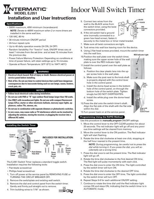
Specifications<br />
• 500W maximum, 40W minimum (incandescent)<br />
NOTE: Derate to 400W maximum when 2 or more timers are<br />
installed in the same wall box.<br />
• 120 VAC, 60 Hz<br />
• 30 minute minimum ON/OFF period<br />
• 24-hour repeat cycle<br />
• Up to 48 daily operation events (24 ON, 24 OFF)<br />
• Random Variability: For “lived in” look, ON/OFF times vary at<br />
least 7 minutes from the set time and at least 15 minutes from<br />
the previous day.<br />
• Power Failure Memory Protection: Depending on conditions at<br />
time of power failure, will retain settings up to 15 minutes.<br />
• Operate at Room Temperature: 32°F (0°C) to 104°F (40°C)<br />
The EJ351 <strong>Switch</strong> <strong>Timer</strong> replaces a standard toggle switch.<br />
Installation requires the following tools:<br />
•<br />
•<br />
1.<br />
2.<br />
3.<br />
4.<br />
MODEL EJ351<br />
• Electrical shock hazard. Risk of injury or death. Remove electrical power at<br />
service panel before installing.<br />
• Risk of fire. Do not use timer to control devices that could have dangerous<br />
consequences due to inaccurate timing such as sun lamps, sauna, heaters,<br />
crock pots, etc.<br />
•<br />
•<br />
•<br />
•<br />
•<br />
Installation and User Instructions<br />
Installing the <strong>Switch</strong> <strong>Timer</strong><br />
Flat-blade screwdriver<br />
Phillips-head screwdriver<br />
WARNING<br />
Follow local electrical codes during installation.<br />
Do not use with PAR or “R”-type outdoor flood lamps larger than 150 watts.<br />
Use ONLY with incandescent lights. Do not use with <strong>com</strong>pact fluorescent<br />
lamps (CFLs), starter or other electronic ballasts, mercury vapor lights, appliances,<br />
radios TVs, stereos, etc.<br />
Do not use in <strong>com</strong>bination with separate dimmers or photoelectric switches.<br />
In rare cases, may cause radio or TV interference which can be resolved by<br />
adjusting the antenna, moving the receiver, or plugging the receiver into a<br />
different AC outlet.<br />
Control<br />
Lever<br />
Plastic<br />
Screw<br />
Cover<br />
Red<br />
Indicator<br />
Light<br />
NOTICE<br />
Control<br />
Panel<br />
Push-Button<br />
Time Dial<br />
Turn off power at the service panel by REMOVING FUSE or<br />
TURNING THE CIRCUIT BREAKER OFF.<br />
Remove the switchplate and existing wall switch.<br />
Remove the dial and control panel from the switch timer.<br />
Gently and firmly pull straight out to remove.<br />
Trim building wires to 7/16” as shown.<br />
INCLUDED FOR INSTALLATION:<br />
Flat<br />
Head<br />
Screws<br />
(2)<br />
Dome<br />
Head<br />
Screw<br />
(1)<br />
Twist<br />
Connectors<br />
(2)<br />
Plastic<br />
7/16”<br />
Screw<br />
Cover<br />
(1)<br />
<strong>Indoor</strong> <strong>Wall</strong> <strong>Switch</strong> <strong>Timer</strong><br />
5.<br />
6.<br />
7.<br />
8.<br />
9.<br />
Connect two wires from the<br />
wall to the BLACK wires from<br />
the switch timer, using the twist<br />
connectors provided.<br />
If the old switch had a ground<br />
wire (normally connected to a<br />
green hex-head screw), fasten it<br />
securely to the metal box or timer metal bracket.<br />
Make sure all twist connectors are tight.<br />
Tuck wires into wall box leaving room for the device.<br />
Using 2 flat-head screws provided, mount the switch timer<br />
into the wall box.<br />
RED Indicator Light<br />
10. Position the wall plate over the switch timer,<br />
making sure the upper screw hole of the wall<br />
plate is over the RED indicator light.<br />
11. Install the control panel over the wall plate as<br />
follows:<br />
a. Position the clear plastic lens into the upper<br />
screw hole in the wall plate.<br />
b. Make sure the post next to the knob shaft<br />
is properly aligned with the control lever<br />
hole in the control panel.<br />
c. Install the dome-head screw in the bottom<br />
hole of the control panel, on through the<br />
bottom hole of the switch plate. Tighten<br />
snugly but DO NOT OVERTIGHTEN.<br />
d. Install the white plug over the dome-head<br />
screw.<br />
12. Press the dial onto the switch timer’s shaft.<br />
Align the flat side of the shaft with the flat side<br />
within the dial.<br />
13. Turn power back on at the service panel.<br />
Programming Using the RAPID Method<br />
BLACK<br />
BLACK<br />
RED<br />
Indicator<br />
Light<br />
Clear<br />
Plastic<br />
Lens<br />
Align with<br />
Hole in<br />
Control Panel<br />
Use this procedure to manually program ON/OFF settings.<br />
1. Move the control lever to the OFF-CLEAR position for about<br />
20 seconds. The red indicator light will go off and any previous<br />
time settings will be cleared from memory.<br />
2. Move the control lever to the ON position. The Red indicator<br />
light will start flashing.<br />
3. Rotate the time dial clockwise at least one click, stopping at<br />
the half hour nearest to the present time.<br />
NOTE: During programming, be careful not to press the<br />
dial while turning it. If you press the dial, you will accidentally<br />
set a wrong time.<br />
1. Press the dial once to set the present time. The Red indicator<br />
light will go off.<br />
2. Rotate the time dial clockwise to the first desired ON time.<br />
The Red light will pulse momentarily with each click.<br />
3. Press the dial once to enter the ON time. The light controlled<br />
by the switch timer will turn ON.<br />
4. Rotate the time dial clockwise to the desired OFF time.<br />
5. Press the dial once to enter the OFF time. The light controlled<br />
by the switch timer will turn OFF.<br />
6. Repeat Steps 5-8 for each additional ON/OFF setting.<br />
7. Continue to rotate the time dial until the Red indicator light<br />
<strong>com</strong>es ON and stays ON, indicating that the switch timer is in<br />
AUTOMATIC mode.
Programming Using the 24-HOUR Method<br />
Use this procedure to automatically program, letting the switch<br />
timer “record” your ON/OFF activities over a 24-hour period,<br />
storing them as programmed settings.<br />
1. Move the control lever to the OFF-CLEAR position for about<br />
20 seconds. The red indicator light will go off and any previous<br />
time settings will be cleared from memory.<br />
2. Move the control lever to the ON position. The Red indicator<br />
light will start flashing.<br />
3. Press the dial as an ON/OFF switch to turn lights ON and OFF<br />
at the ON and OFF times you desire for the first 24 hours.<br />
4. At the end of the 24-hour period, the switch timer will be programmed<br />
and the Red indicator light will stay ON, indicating<br />
that the switch timer is in AUTOMATIC mode.<br />
Reviewing the Settings Stored in Memory<br />
Use this procedure to check the settings programmed into the<br />
switch timer.<br />
NOTE: Reviewing will not change or delete the program. The<br />
only way to delete a program is to move the control lever to<br />
the OFF-CLEAR position for about 20 seconds. This clears the<br />
entire memory.<br />
1. Make sure the switch timer is in AUTOMATIC mode, with the<br />
Red indicator light flashing.<br />
2. Rotate the time dial clockwise at least one click, stopping at<br />
the nearest half hour to the present time.<br />
3. Press the dial once to start the Review cycle. The Red indicator<br />
light will go OFF.<br />
Observed Problem<br />
The <strong>Switch</strong> <strong>Timer</strong> cannot be programmed using the<br />
RAPID method.<br />
The <strong>Switch</strong> <strong>Timer</strong> does not turn lights ON and OFF<br />
automatically, as programmed.<br />
The <strong>Switch</strong> <strong>Timer</strong> does not turn light ON or OFF when<br />
pressing on the Dial.<br />
The <strong>Switch</strong> <strong>Timer</strong> is warm to the touch.<br />
The controlled light flickers or goes to half brightness.<br />
Troubleshooting Guide<br />
What to Do<br />
Was the timer correctly programmed according to the instructions? If not, try again.<br />
Make sure the Control Lever is in the ON position.<br />
Make sure the Red Indicator Light is flashing before beginning programming.<br />
Make sure you have set the Current Time before programming ON/OFF times.<br />
Make sure you are pressing the Dial fully during the programming sequence.<br />
Was the timer correctly programmed according to the instructions? If not, try again.<br />
Make sure the timer is not accidentally in MANUAL mode, with the Red indicator light OFF.<br />
Make sure the controlled light bulb(s) is tight in its socket and is not burned out.<br />
Check the wiring for any loose connections.<br />
Make sure the controlled light bulb(s) is tight in its socket and is not burned out.<br />
Check the wiring for any loose connections.<br />
Check for a burned out fuse or circuit breaker.<br />
Some warmth is normal. Be sure the <strong>com</strong>bined light bulb wattage does not exceed 500 watts.<br />
Recheck the wiring.<br />
4. Rotate the time dial slowly clockwise, observing the time<br />
shown on the dial when the light controlled by the switch<br />
timer goes ON and OFF.<br />
5. Press the dial once to end the Review cycle. The Red indicator<br />
light will go ON and stay ON, indicating that the switch timer<br />
is in AUTOMATIC mode.<br />
Everyday Use of the EJ351 <strong>Switch</strong> <strong>Timer</strong><br />
• The time dial does not rotate automatically to function as a<br />
clock (reflecting the time of day). After programming is <strong>com</strong>plete,<br />
the time dial functions only as an ON/OFF switch.<br />
• The <strong>Switch</strong> <strong>Timer</strong> can be used in either of two modes. To<br />
switch between modes, quickly press the dial twice:<br />
- AUTOMATIC MODE: The <strong>Switch</strong> <strong>Timer</strong> will turn the light<br />
ON or OFF according to programmed settings. RED indicator<br />
light stays ON when in Automatic Mode.<br />
NOTE: Even in AUTOMATIC Mode, press the dial to<br />
manually turn the light ON or OFF. While this will override<br />
the current program, it will not disturb the next one.<br />
- MANUAL MODE: Programmed settings are inactive, and<br />
the <strong>Switch</strong> <strong>Timer</strong> will only turn the light ON or OFF when<br />
you push on the dial. RED indicator light stays OFF when in<br />
Manual mode.<br />
• When the controlled light bulb burns out, the red indicator<br />
light will also go off and timer settings are affected. Change<br />
the bulb as follows:<br />
a. Move the Control Lever to the OFF-CLEAR position.<br />
b. Replace the bulb.<br />
c. Move the control lever back to the ON position.<br />
d. Reprogram the timer settings.<br />
LIMITED ONE-YEAR WARRANTY<br />
If within one (1) year from the date of purchase, this product fails due to a defect in material or workmanship, Intermatic Incorporated will repair or replace it, at its sole option, free of charge. This warranty is<br />
extended to the original household purchaser only and is not transferable. This warranty does not apply to: (a) damage to units caused by accident, dropping or abuse in handling, acts of God or any negligent<br />
use; (b) units which have been subject to unauthorized repair, opened, taken apart or otherwise modified; (c) units not used in accordance with instructions; (d) damages exceeding the cost of the product; (e)<br />
sealed lamps and/or lamp bulbs, LED’s and batteries; (f) the finish on any portion of the product, such as surface and/or weathering, as this is considered normal wear and tear; (g) transit damage, initial installation<br />
costs, removal costs, or reinstallation costs.<br />
INTERMATIC INCORPORATED WILL NOT BE LIABLE FOR INCIDENTAL OR CONSEQUENTIAL DAMAGES. SOME STATES DO NOT ALLOW THE EXCLUSION OR LIMITATION OF INCIDENTAL OR CONSEQUENTIAL<br />
DAMAGES, SO THE ABOVE LIMITATION OR EXCLUSION MAY NOT APPLY TO YOU. THIS WARRANTY IS IN LIEU OF ALL OTHER EXPRESS OR IMPLIED WARRANTIES. ALL IMPLIED WARRANTIES, INCLUDING<br />
THE WARRANTY OF MERCHANTABILITY AND THE WARRANTY OF FITNESS FOR A PARTICULAR PURPOSE, ARE HEREBY MODIFIED TO EXIST ONLY AS CONTAINED IN THIS LIMITED WARRANTY, AND SHALL<br />
BE OF THE SAME DURATION AS THE WARRANTY PERIOD STATED ABOVE. SOME STATES DO NOT ALLOW LIMITATIONS ON THE DURATION OF AN IMPLIED WARRANTY, SO THE ABOVE LIMITATION MAY<br />
NOT APPLY TO YOU.<br />
This warranty service is available by either (a) returning the product to the dealer from whom the unit was purchased, or (b) mailing the product, along with proof of purchase, postage prepaid to the authorized<br />
service center listed below. This warranty is made by: Intermatic Incorporated/After Sales Service/7777 Winn Rd., Spring Grove, Illinois 60081-9698/815-675-7000 http://www.intermatic.<strong>com</strong> Please be sure to<br />
wrap the product securely to avoid shipping damage.<br />
INTERMATIC INCORPORATED, SPRING GROVE, ILLINOIS 60081-9698<br />
158--00545