Testing of Plastics - Polymer Service GmbH Merseburg
Testing of Plastics - Polymer Service GmbH Merseburg
Testing of Plastics - Polymer Service GmbH Merseburg

You also want an ePaper? Increase the reach of your titles
YUMPU automatically turns print PDFs into web optimized ePapers that Google loves.
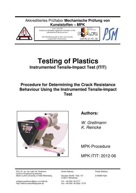
Akkreditiertes Prüflabor Mechanische Prüfung von<br />
Kunstst<strong>of</strong>fen – MPK<br />
<strong>Testing</strong> <strong>of</strong> <strong>Plastics</strong><br />
Instrumented Tensile-Impact Test (ITIT)<br />
Procedure for Determining the Crack Resistance<br />
Behaviour Using the Instrumented Tensile-Impact<br />
Test<br />
Authors:<br />
W. Grellmann<br />
K. Reincke<br />
MPK-Procedure<br />
MPK-ITIT: 2012-06<br />
Pr<strong>of</strong>. Dr. rer. nat. habil. W. Grellmann<br />
Centre <strong>of</strong> Engineering Sciences<br />
Martin-Luther-University <strong>of</strong> Halle-Wittenberg<br />
wolfgang.grellmann@psm.uni-halle.de<br />
http://www.kunstst<strong>of</strong>fdiagnostik.de<br />
Street Address:<br />
Geusaer Straße / Geb. 131<br />
D-06217 <strong>Merseburg</strong><br />
Tel.: +49 3461 46 2777<br />
Fax: +49 3461 46 2592 / 2779<br />
Postal Address:<br />
D-06099 Halle
Content<br />
1 Application 1<br />
2 Short Description 1<br />
3 Determination <strong>of</strong> Parameters Related to the Resistance Against Unstable<br />
Crack Propagation<br />
2<br />
3.1 Summary <strong>of</strong> the Test Method 2<br />
3.2 Specimens 2<br />
3.3 Performance 3<br />
3.4 Analysis 3<br />
3.4.1 General 3<br />
3.4.2 Determination <strong>of</strong> Fracture Mechanical Parameters 4<br />
3.4.3 Validation <strong>of</strong> the Fracture Mechanical Parameters 4<br />
3.4.3.1 Validation <strong>of</strong> Experimental Conditions 4<br />
3.4.3.2 Requirements on Specimen Geometry 4<br />
4 Literature 5
MPK-Procedure MPK-ITIT: 2012-06 1<br />
Procedure for Determining the Crack Resistance Behaviour<br />
Using the Instrumented Notched Tensile-Impact Test (ITIT)<br />
W. Grellmann and K. Reincke, <strong>Merseburg</strong><br />
1 Application<br />
The instrumented notched tensile-impact test is used for the determination <strong>of</strong> toughness<br />
properties <strong>of</strong> polymeric materials for which the performance <strong>of</strong> the instrumented<br />
Charpy impact test is not possible because <strong>of</strong> the specimen thickness and/or low material<br />
stiffness. This method should be applied especially within testing <strong>of</strong> polymeric<br />
sheets and elastomers [1–6]. In comparison to the instrumented Charpy impact test<br />
[7], instrumented notched tensile-impact tests have been reported in the literature<br />
relatively seldom. However, publications [8–14] show, that instrumented notched tensile-impact<br />
test is a helpful tool to describe the material properties as a function <strong>of</strong><br />
structural parameters and/or experimental conditions such as temperature or loading<br />
speed.<br />
In some <strong>of</strong> the cited publications it is described that instrumented tensile-impact tests<br />
with unnotched specimens are used to record stress–strain diagrams. These diagrams<br />
are the basis <strong>of</strong> the following determination <strong>of</strong> stress and strain at break for<br />
example. For this reason, it is important to distinguish between notched tensileimpact<br />
tests and tensile-impact tests.<br />
In principle, the instrumented notched tensile-impact test is an extension <strong>of</strong> the<br />
conventional notched tensile-impact test according to ISO 8256 [15] and is performed<br />
with specimens with razor-blade notches.<br />
During loading <strong>of</strong> the specimen, load–time signal is recorded. Resulting material parameters<br />
can be used for quality control as well as for research and development.<br />
2 Short Description<br />
Examinations for determination <strong>of</strong> toughness are performed with the pendulum device<br />
Resil Impactor Junior 25 according to ISO 13802 [16]. This pendulum device has<br />
a working capacity <strong>of</strong> 4 J, 7.5 J, 15 J and 25 J at maximum falling angle (150°). For<br />
the test, a specimen is fixed between a stationary clamp and a cross head. In contrast<br />
to Charpy impact testing, during notched tensile-impact testing, no direct contact<br />
<strong>of</strong> the pendulum hammer and the specimen takes place. The pendulum hammer hits<br />
the cross head which is fixed to the specimen. In this way, the specimen is deformed<br />
in direction <strong>of</strong> its longitudinal axis until fracture occurs. Therefore, a tensile-impact<br />
test with unnotched specimens is a uniaxial tensile test with a high deformation<br />
speed. The metallic pendulum hammer consists <strong>of</strong> a tubular pendulum arm and an<br />
impact construction with metallic blocks at both sides, which meet the cross head.<br />
After release, the pendulum hammer moves in a circle and transfers part <strong>of</strong> its kinetic<br />
energy to the cross head and therefore, indirectly to the specimen, at the lowest point<br />
<strong>of</strong> its trajectory.<br />
For short pendulum hammers (up to 4 J working capacity at maximum falling angle),<br />
the testing speed at zero crossing is 2.9 m/s. Larger pendulum hammers have a<br />
larger pendulum length and therefore, their velocity at the zero crossing is 3.7 m/s.<br />
Specimens have a rectangular cross-section and are double-edge notched.
MPK-Procedure MPK-ITIT: 2012-06 2<br />
Recording <strong>of</strong> the load (F)–time (t) signal is realised over a piezo load cell, which is<br />
integrated in the stationary clamp. Measuring range is 4 kN.<br />
From the F-t diagrams, the deformation (in this case the extension) can be calculated<br />
from Newton’s second law. In a first integration step (1), the velocity can be determined,<br />
and in a second integration step (2), the extension l <strong>of</strong> the specimen as a<br />
function <strong>of</strong> time:<br />
t<br />
1<br />
v(t ) = v0 − ∫F(<br />
τ ) dτ<br />
(1)<br />
m<br />
l(t<br />
)<br />
t<br />
=∫<br />
0<br />
0<br />
v( τ ) dτ<br />
(2)<br />
A direct measurement <strong>of</strong> the extension does not take place. The F-t signal is transferred<br />
to a personal computer over a data acquisition system. By using the belonging<br />
s<strong>of</strong>tware DAS4Win, one is able to display and analyse load–time diagrams. In Figure<br />
1, one can see a schematic F–l diagram <strong>of</strong> an elastomer. Analysis <strong>of</strong> such diagrams<br />
is done by determining firstly the maximum load F max and the extension at F max l max .<br />
Further, the area under the F–l diagram is split into two parts: energy up to maximum<br />
load A max and a so-called crack propagation energy A p .<br />
F<br />
Load F<br />
A<br />
Extension l<br />
l max<br />
A p<br />
Fig. 1:<br />
Characteristic load–extension diagram with crack propagation energy (F max<br />
–<br />
maximum load; l max – maximum extension; A max – energy up to F max ; A P –<br />
crack propagation energy)<br />
3 Determination <strong>of</strong> Parameters Related to the Resistance Against<br />
Unstable Crack Propagation<br />
3.1 Summary <strong>of</strong> the Test Method<br />
Aim <strong>of</strong> the tests is the determination <strong>of</strong> fracture mechanical material parameters. This<br />
method is only valid for double-edge-notched tension (DENT) specimens <strong>of</strong> polymers<br />
with a sharp crack. Starting from load–extension diagrams, stress intensity factors K t<br />
and J values J d can be calculated.<br />
3.2 Specimens<br />
According to ISO 8256 [15], DENT specimens with following dimensions are to pre-
fer:<br />
MPK-Procedure MPK-ITIT: 2012-06 3<br />
• Width W = 10 mm<br />
• Length L = 80 mm and 64 mm, respectively<br />
The notching is carried out preferably with metal blades by a pneumatic notching device<br />
on the narrow sides <strong>of</strong> the specimen up to an initial crack length <strong>of</strong> 2 mm, this<br />
means 1 mm at each side. The surfaces must be free <strong>of</strong> scratches, craters, depressions<br />
and flashes.<br />
Before testing the specimens, the thickness and width must be measured with a<br />
precision <strong>of</strong> 0.01 mm. The results must be recorded. At least 10 specimens should be<br />
tested, after storage in the testing room for 12 h.<br />
3.3 Performance<br />
For a material characterization at room temperature, normalisation <strong>of</strong> the specimens<br />
and experiments must be carried out under standard conditions according to ISO 291<br />
[17] with a temperature <strong>of</strong> 23°C and a relative air humidity <strong>of</strong> 50 % (referred to as<br />
“climate 23/50”) [18]. If deviations occur or if variation from the standard conditions is<br />
necessary, this must be reported.<br />
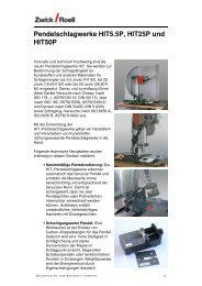
The specimen must be fixed parallel between the stationary clamp and the cross<br />
head in that way that the pendulum hammer hits the cross head at the lowest point <strong>of</strong><br />
the circle motion (see Figure 2). Initial gauge length l 0 is 30 mm, the notches must be<br />
in the middle <strong>of</strong> l 0 . Experiments with elastomers should preferably be performed at<br />
maximum falling angle. This corresponds to a hammer speed <strong>of</strong> 2.9 or 3.7 m/s, respectively.<br />
When testing thermoplastic sheets, the hammer speed must be 1 m/s or<br />
1,5 m/s (corresponding to a falling angle <strong>of</strong> 40° or 60°).<br />
Fig. 2: Schematic representation <strong>of</strong> fracture mechanics testing device for performance<br />
<strong>of</strong> instrumented notched tensile-impact tests<br />
Recording <strong>of</strong> load–extension diagrams is carried out according to the service manual<br />
<strong>of</strong> the pendulum device.
MPK-Procedure MPK-ITIT: 2012-06 4<br />
3.4 Analysis<br />
3.4.1 General<br />
For analysis, the Ceast s<strong>of</strong>tware „DAS4WIN extended“ should be used. After the test,<br />
the recorded load–extension diagram is displayed. As it is shown in Figure 1, at first<br />
maximum load F max and extension at maximum load l max must be determined. Furthermore,<br />
energy A max (corresponds to the area under the diagram up to F max ) and<br />
crack propagation energy A P are to be specified. The s<strong>of</strong>tware allows to print each F–<br />
l diagram and to save it in ASCII data format.<br />
Subsequent changes within settings (for example test duration) or changes <strong>of</strong> F-l diagrams<br />
are not possible.<br />
3.4.2 Determination <strong>of</strong> Fracture Mechanical Parameters<br />
For impact toughness characterization <strong>of</strong> polymers with thermoplastic and elastomeric<br />
matrix according to this procedure, following material parameter J Qd is to prefer<br />
[18]:<br />
J-Werte J Qd<br />
( )<br />
J<br />
Q d<br />
η Amax<br />
=<br />
B W − a<br />
(3)<br />
with<br />
⎛ a ⎞ ⎛ a ⎞ ⎛ a ⎞<br />
η = − 0,<br />
06 + 5,<br />
99⎜<br />
⎟ − 7,<br />
42⎜<br />
⎟ + 3,<br />
29⎜<br />
⎟<br />
⎝W<br />
⎠ ⎝W<br />
⎠ ⎝W<br />
⎠<br />
2<br />
3<br />
The determination <strong>of</strong> further characteristic values depends on technical requirements.<br />
These values must be reported in the testing protocol.<br />
3.4.3. Validation <strong>of</strong> the Fracture Mechanical Parameters<br />
3.4.3.1. Validation <strong>of</strong> Experimental Conditions<br />
For the determination <strong>of</strong> characteristic fracture mechanics parameters using the<br />
notched tensile-impact test, the following experimental conditions must be checked<br />
[7,15–18].<br />
- energy absorption (A max +A P )<br />
Checking <strong>of</strong> the energy absorption is done according to ISO 8256, whereby the absorbed<br />
energy (A max +A P ) must be in the range between 20 and 80% <strong>of</strong> the maximum<br />
energy <strong>of</strong> the pendulum hammer A H .<br />
( Am<br />
+ AP<br />
) 0.<br />
H<br />
0 ≤ A<br />
(4)<br />
. 2AH ax ≤ 8<br />
- speed <strong>of</strong> the pendulum hammer v H<br />
Speed <strong>of</strong> the pendulum hammer should be reduced during the test only by 20 %.
MPK-Procedure MPK-ITIT: 2012-06 5<br />
3.4.3.2 Requirements on Specimen Geometry<br />
For the determination <strong>of</strong> geometry-independent material parameters, a plane strain<br />
state must be occurring within the specimen. For this, a certain specimen thickness<br />
and a certain notch depth is necessary. When testing very thin specimens (for example<br />
from extrusion or blow films), one must assume that because <strong>of</strong> the small thickness<br />
a plane stress state predominates.<br />
In this case, the material parameters from the instrumented notched tensile-impact<br />
test can be used to compare materials, for example within a modification series.<br />
However, these results cannot be transferred to other geometries. This aspect must<br />
be noted within the test report.<br />
4 Literature<br />
[1] Grellmann, W., Reincke, K. (2004): Quality Improvement <strong>of</strong> Elastomers. Use <strong>of</strong><br />
Instrumented Notched Tensile-Impact <strong>Testing</strong> for Assessment <strong>of</strong> Toughness.<br />
Materialprüfung 46 (2004) 4, 168–175<br />
[2] Reincke, K., Grellmann, W. (2003): Anwendung der instrumentierten Schlagzugprüfung<br />
in der Kunstst<strong>of</strong>ftechnik. In: Buchholz, O. W. und Geisler, S. (Hrsg.)<br />
Herausforderung durch den industriellen Fortschritt - Tagungsband Werkst<strong>of</strong>fprüfung<br />
2003, Verlag Stahleisen <strong>GmbH</strong> Düsseldorf, 322–328<br />
[3] Reincke, K., Grellmann, W., Lach, R., Heinrich, G. (2003): Toughness Optimization<br />
<strong>of</strong> SBR Elastomers – Use <strong>of</strong> Fracture Mechanics Methods for Characterization.<br />
Macromolecular Materials and Engineering, 288, 181–189<br />
[4] Reincke, K., Heinrich, G., Grellmann, W. (2004): Investigation <strong>of</strong> Mechanical<br />
and Fracture Mechanical Properties <strong>of</strong> Elastomers Filled with Precipitated Silica<br />
and Nan<strong>of</strong>iller Based upon Layered Silicates. Rubber Chemistry and Technology<br />
77/4, 662–677<br />
[5] Grellmann, W., Reincke, K. (2005): Elastomere Werkst<strong>of</strong>fe – Qualitätsprüfung<br />
mit Hilfe des instrumentierten Kerbschlagzugversuches. Dichtungstechnik Jahrbuch<br />
2005, 128–130<br />
[6] Reincke, K., Grellmann, W., Heinrich, G. (2004): Anwendung bruchmechanischer<br />
Methoden zur Risszähigkeitsbewertung von Elastomeren. 6. Kautschuk-<br />
Herbst-Kolloquium, 10.–13.11.2004, Hannover, Tagungsband, 601–612<br />
[7] Grellmann, W., Seidler, S., Hesse, W.: <strong>Testing</strong> <strong>of</strong> <strong>Plastics</strong> – Instrumented Charpy<br />
Impact Test; Procedure for Determining the Crack Resistance Behaviour Using<br />
the Instrumented Impact Test; Part I: Determination <strong>of</strong> Characteristic Fracture<br />
Mechanics Parameters for Resistance Against Stable Crack Propagation<br />
MPK-ICIT (2012); http://www2.iw.uni-halle.de/ww/mpk/p_e.pdf<br />
[8] Bekar, I., Fatt, M.S.H., Padovan, J. (2002): Deformation and Fracture <strong>of</strong> Rubber<br />
under Tensile Impact Loading. Tire Sci. Techn. 30, 45–58<br />
[9] Bucknall, C. B., Ajroldi, G. (2001): Blends Containing Core-Shell Impact Modifiers.<br />
Part 3 - Effects <strong>of</strong> Temperature on Tensile Impact Behaviour. Plast. Rubb.<br />
Comp. 30, 377–383<br />
[10] Dijkstra, K., ter Laak, J., Gaymans, R. J. (1994): Nylon-6/Rubber Blends: 6.<br />
Notched Tensile Impact <strong>Testing</strong> <strong>of</strong> Nylon-6/(Ethylene-Propylene Rubber)<br />
Blends. <strong>Polymer</strong> 35, 315–322
MPK-Procedure MPK-ITIT: 2012-06 6<br />
[11] Karger-Kocsis, J., Benevolenski, O. I., Moskala, E. J. (2001): Toward Understanding<br />
the Stress Oscillation Phenomenon in <strong>Polymer</strong>s Due to Tensile Impact<br />
Loading. J. Mater. Sci. 36, 3365–3371<br />
[12] Mouzakis, D. E., Karger-Kocsis, J. (1998): Effects <strong>of</strong> Gasoline Absorption on the<br />
Tensile Impact Response <strong>of</strong> HDPE/Selar Laminar Microlayer Composites. J.<br />
Appl. Polym. Sci. 68, 561–569<br />
[13] Fernie, R., Warrior, N. A. (2002): Impact Test Rigs for High Strain Rate Tensile<br />
and Compressive <strong>Testing</strong> <strong>of</strong> Composite Materials. Strain, 38, 69–73<br />
[14] Louis, H., Reckleben, A. (1996): Analyse des dynamischen Reißverhaltens von<br />
Elastomeren. In Tagungsband: Kautschuk-Herbst-Kolloquium 1996, Hannover,<br />
24.–26. Oktober, 1–9<br />
[15] ISO 8256 (2004): <strong>Plastics</strong> – Determination <strong>of</strong> Tensile-Impact Strength<br />
[16] ISO 13802 (1999): <strong>Plastics</strong> – Verification <strong>of</strong> Pendulum <strong>Testing</strong> Machines –<br />
Charpy, Izod and Tensile-Impact <strong>Testing</strong><br />
[17] ISO 291 (2008): <strong>Plastics</strong> – Standard Atmospheres for Conditioning and <strong>Testing</strong><br />
[18] Grellmann, W., Seidler S. (2007): <strong>Plastics</strong> <strong>Testing</strong>, Carl Hanser Verlag München,<br />
Wien, New York