
You also want an ePaper? Increase the reach of your titles
YUMPU automatically turns print PDFs into web optimized ePapers that Google loves.
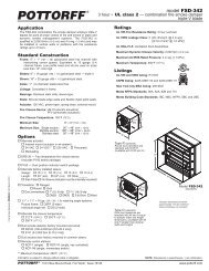
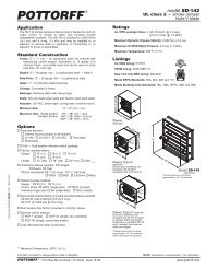
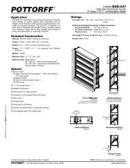
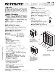
Actuator and Sleeve Dimensional Data<br />
The drawings and corresponding table show the position of the damper when mounted in a<br />
factory sleeve and the relative space required for a given actuator. The standard mounting<br />
locations provide enough space for installation of retaining angles and duct connections.<br />
Actuator<br />
Model<br />
X Dimension<br />
Minimum<br />
Damper Size (w x h)<br />
FSLF120/24 and 11" (279) 6" (<strong>152</strong>) 10" x 8"<br />
FSTF120 (H < 15") (H ≥ 15") (254 x 203)<br />
FSNF120/24 14" (356) 11" (279) 10" x 10"<br />
(H < 18") (H ≥ 18") (254 x 254)<br />
MS4120/8120 15" (381) 12" (305) 10" x 10"<br />
(H < 18") (H ≥ 18") (254 x 254)<br />
ML4115/8115 10 1 /2" (267) 7 1 /2" (191) 10" x 8"<br />
MS4209/8209 (H < 13") (H ≥ 13") (254 x 203)<br />
8" (203)<br />
331-4826 N/A<br />
10" x 20"<br />
(H ≥ 20") (254 x 508)<br />
NOTE:<br />
1. Damper may be rotated 180° to position actuator on right side.<br />
2. For dimensions on actuators not shown above, contact factory.<br />
3. If actuator is ordered with optional external mount, sleeve<br />
flange should be ordered loose, for field assembly.<br />
3-1/4"<br />
(83)<br />
14-1/2"<br />
(368)<br />
Max.<br />
X<br />
Sleeve Length<br />
10" (254) + X<br />
5"<br />
(127)<br />
1-3/4"<br />
(44)<br />
3/4"<br />
(19)<br />
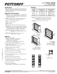
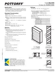
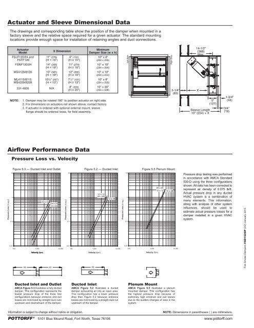
Airflow Performance Data<br />
Pressure Loss vs. Velocity<br />
Figure 5.3 — Ducted Inlet and Outlet Figure 5.2 — Ducted Inlet Figure 5.5 Plenum Mount<br />
5D 6D 5D<br />
Pressure drop testing was performed<br />
in accordance with AMCA Standard<br />
500-D using the three configurations<br />
shown. All data has been corrected to<br />
represent air density of 0.075 lb/ft.<br />
Actual pressure drop in any ducted<br />
HVAC system is a combination of<br />
many elements. This information,<br />
along with analysis of other system<br />
influences, should be used to<br />
estimate actual pressure losses for a<br />
damper installed in a given HVAC<br />
system.<br />
Fire Smoke Dampers <strong>FSD</strong><strong>152</strong><strong>OP</strong> (2/2) January 2013<br />
Ducted Inlet and Outlet<br />
AMCA Figure 5.3 Illustrates a fully ducted<br />
damper. This configuration represents the<br />
lowest pressure drop of the three test<br />
configurations because entrance and exit<br />
losses are minimized by straight duct runs<br />
upstream and downstream of the damper.<br />
Ducted Inlet<br />
AMCA Figure 5.2 Illustrates a ducted<br />
damper exhausting air into an open area.<br />
This configuration has a lower pressure<br />
drop than Figure 5.5 because entrance<br />
losses are minimized by a straight duct run<br />
upstream of the damper.<br />
Plenum Mount<br />
AMCA Figure 5.5 Illustrates a plenum<br />
mounted damper. This configuration has<br />
the highest pressure drop because of<br />
extremely high entrance and exit losses<br />
due to the sudden changes of area in the<br />
system.<br />
Information is subject to change without notice or obligation.<br />
NOTE: Dimensions in parentheses ( ) are millimeters.<br />
POTTORFF ® 5101 Blue Mound Road, Fort Worth, Texas 76106 www.pottorff.com