
Create successful ePaper yourself
Turn your PDF publications into a flip-book with our unique Google optimized e-Paper software.
STATE OF CALIFORNIA<br />
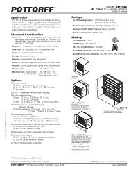
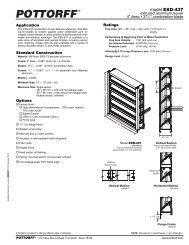
<strong>model</strong> <strong>FSD</strong>-<strong>152</strong>-<strong>OP</strong><br />
1 1 /2 hour • UL class 2 — combination fire smoke damper<br />
airfoil blade — out-of-partition<br />
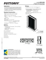
Application<br />
The <strong>FSD</strong>-<strong>152</strong>-<strong>OP</strong> combination fire smoke damper employs<br />
airfoil blades for point-of-origin control of fire and smoke in static<br />
and dynamic smoke management systems. These specialty<br />
dampers are approved for installation with the closed plane of<br />
the blades up to 14 1 /2" (368) outside the fire rated partition and<br />
come standard with the actuator in the airstream allowing for<br />
direct service access from the face of the damper through the<br />
HVAC grille. The <strong>FSD</strong>-<strong>152</strong>-<strong>OP</strong> is qualified to 4,000 ft/min (20.3<br />
m/s) and 4 in.wg. (1.0 kPa) and may be installed in vertical walls<br />
and partitions, or horizontally in floors or assemblies with fire<br />
resistance ratings up to 2 hours.<br />
Standard Construction<br />
Frame: 5" × 1" (127 × 25) galvanized steel hat channel with<br />
interlocking corner gusset. Equivalent to 13 gauge (2.4)<br />
channel frame. Low profile head and sill are used on sizes<br />
less than 13" (330) high.<br />
Blades: 6" × 14 gauge (<strong>152</strong> × 2.0) equivalent galvanized — steel<br />
airfoil.<br />
Sleeve: 16" × 20 gauge (406 × 1.0) galvanized steel.<br />
Axles: 1 /2" (13) diameter plated steel hex.<br />
Linkage: Concealed in frame.<br />
Bearings: Stainless steel oilite, sleeve-type.<br />
Seals: Silicone blade edge seals integrally rolled and<br />
mechanically fastened to blades. Flexible metal jamb seals.<br />
Actuator: 120 VAC, power-open, spring-close, internal mount.<br />
Fire Closure Device: HS-10 (electric actuators)<br />
PFV (pneumatic actuators)<br />
Fire Closure Temperature: 165°F (75°C).<br />
Ratings<br />
UL 555 Fire Resistance Rating: 1 1 /2 hour (vertical and horizontal)<br />
UL 555S Leakage Class: 2 [20 cfm/sq.ft. @ 4 in.wg.]<br />
[(0.10 m 3 /s/m 2 @ 1.0 kPa)]<br />
Maximum Dynamic Closure Velocity: 4,000 fpm (20.3 m/s)<br />
Maximum UL555S Rated Pressure: 4 in.wg. (1.0 kPa)<br />
Maximum Temperature: 350°F (177°C)<br />
Listings<br />
UL 555 and 555S listing: R11767<br />
CSFM listing: 3225-0368:115 and 3230-0368:116<br />
New York City MEA listing: 295-98-E<br />
Meets NFPA Standards: 90A, 92A, 92B and 101<br />
Meets Building Code Standards: IBC, NBC, NFPA, SBC and UBC<br />
L<br />
S<br />
IS<br />
STAT E<br />
E<br />
R<br />
T<br />
V<br />
IN G<br />
I<br />
E<br />
FIR E M ARS HALL<br />
C<br />
Minimum Size: 10" × 8" (250 × 203)<br />
Maximum Size: 36" × 36" (914 × 914)<br />
Fire Smoke Dampers <strong>FSD</strong><strong>152</strong><strong>OP</strong> (1/2) January 2013<br />
Options<br />
o Alternate actuator:<br />
o External Mount<br />
o 24 VAC o 230 VAC o Pneumatic<br />
o DRS-30 — Two temperature fire closure device.<br />
(Includes PI-50 switch package)<br />
o PI-50 — Dual position indicator switch package.<br />
o Alternate factory installed sleeve:<br />
Gauge: o 18 (1.3) o 16 (1.6) o 14 (2.0) o 10 (3.5)<br />
o Net O.D. (sleeve I.D. will be approximately 3 /8" (9) under<br />
nominal duct size opening).<br />
o Transitions: o Round o Oval<br />
o Duct connections: o 1" (25) S-clip o 1 1 /2" (38) S-clip<br />
o DM25 o DM35 o WARD<br />
o Alternate fire closure temperature:<br />
o 212°F (100°C) o 250°F (121°C)<br />
o 350°F (177°C).<br />
o Duct smoke detector factory mounted and wired:<br />
o 2151 (0-3,000 fpm [0-15.2 m/s])<br />
o Remote control stations:<br />
o RCP-1 (single) o RCP-1K (single, key controlled)<br />
o RCP-1M (single, momentary switch)<br />
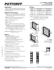
Model <strong>FSD</strong>-<strong>152</strong>-<strong>OP</strong><br />
(standard)<br />
*Standard sleeve O.D. including thermal blanket<br />
wrap, is approximately 3/8" (9) over nominal duct<br />
size. Standard sleeve I.D. is approximately nominal<br />
duct size.<br />
NOTE: The opening for the damper<br />
assembly in the fire wall must be sized<br />
appropriately. If not, serious damage to<br />
the thermal blanket wrap could occur and<br />
this will nullify the U.L. rating.<br />
Contact the factory if necessary for<br />
additional information.<br />
Information is subject to change without notice or obligation.<br />
NOTE: Dimensions in parentheses ( ) are millimeters.<br />
POTTORFF ® 5101 Blue Mound Road, Fort Worth, Texas 76106 www.pottorff.com
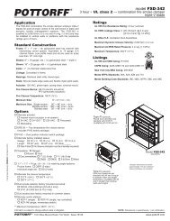
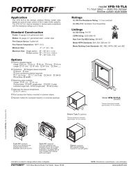
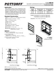
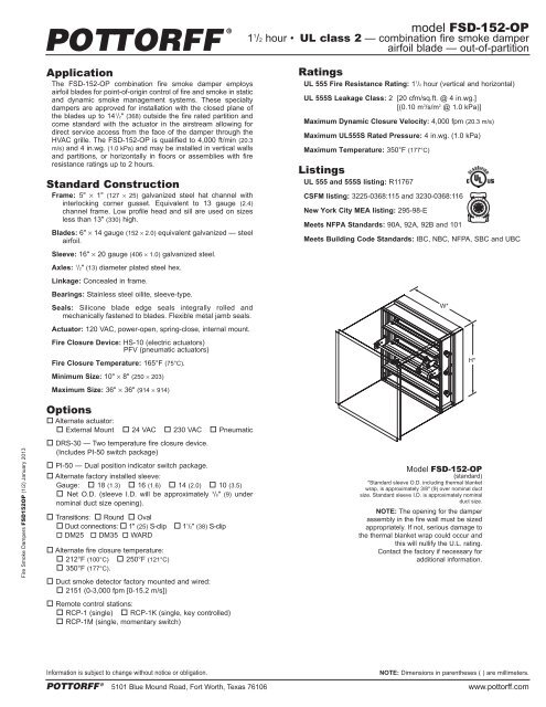
Actuator and Sleeve Dimensional Data<br />
The drawings and corresponding table show the position of the damper when mounted in a<br />
factory sleeve and the relative space required for a given actuator. The standard mounting<br />
locations provide enough space for installation of retaining angles and duct connections.<br />
Actuator<br />
Model<br />
X Dimension<br />
Minimum<br />
Damper Size (w x h)<br />
FSLF120/24 and 11" (279) 6" (<strong>152</strong>) 10" x 8"<br />
FSTF120 (H < 15") (H ≥ 15") (254 x 203)<br />
FSNF120/24 14" (356) 11" (279) 10" x 10"<br />
(H < 18") (H ≥ 18") (254 x 254)<br />
MS4120/8120 15" (381) 12" (305) 10" x 10"<br />
(H < 18") (H ≥ 18") (254 x 254)<br />
ML4115/8115 10 1 /2" (267) 7 1 /2" (191) 10" x 8"<br />
MS4209/8209 (H < 13") (H ≥ 13") (254 x 203)<br />
8" (203)<br />
331-4826 N/A<br />
10" x 20"<br />
(H ≥ 20") (254 x 508)<br />
NOTE:<br />
1. Damper may be rotated 180° to position actuator on right side.<br />
2. For dimensions on actuators not shown above, contact factory.<br />
3. If actuator is ordered with optional external mount, sleeve<br />
flange should be ordered loose, for field assembly.<br />
3-1/4"<br />
(83)<br />
14-1/2"<br />
(368)<br />
Max.<br />
X<br />
Sleeve Length<br />
10" (254) + X<br />
5"<br />
(127)<br />
1-3/4"<br />
(44)<br />
3/4"<br />
(19)<br />
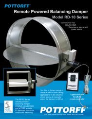
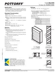
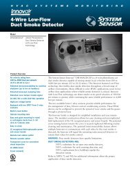
Airflow Performance Data<br />
Pressure Loss vs. Velocity<br />
Figure 5.3 — Ducted Inlet and Outlet Figure 5.2 — Ducted Inlet Figure 5.5 Plenum Mount<br />
5D 6D 5D<br />
Pressure drop testing was performed<br />
in accordance with AMCA Standard<br />
500-D using the three configurations<br />
shown. All data has been corrected to<br />
represent air density of 0.075 lb/ft.<br />
Actual pressure drop in any ducted<br />
HVAC system is a combination of<br />
many elements. This information,<br />
along with analysis of other system<br />
influences, should be used to<br />
estimate actual pressure losses for a<br />
damper installed in a given HVAC<br />
system.<br />
Fire Smoke Dampers <strong>FSD</strong><strong>152</strong><strong>OP</strong> (2/2) January 2013<br />
Ducted Inlet and Outlet<br />
AMCA Figure 5.3 Illustrates a fully ducted<br />
damper. This configuration represents the<br />
lowest pressure drop of the three test<br />
configurations because entrance and exit<br />
losses are minimized by straight duct runs<br />
upstream and downstream of the damper.<br />
Ducted Inlet<br />
AMCA Figure 5.2 Illustrates a ducted<br />
damper exhausting air into an open area.<br />
This configuration has a lower pressure<br />
drop than Figure 5.5 because entrance<br />
losses are minimized by a straight duct run<br />
upstream of the damper.<br />
Plenum Mount<br />
AMCA Figure 5.5 Illustrates a plenum<br />
mounted damper. This configuration has<br />
the highest pressure drop because of<br />
extremely high entrance and exit losses<br />
due to the sudden changes of area in the<br />
system.<br />
Information is subject to change without notice or obligation.<br />
NOTE: Dimensions in parentheses ( ) are millimeters.<br />
POTTORFF ® 5101 Blue Mound Road, Fort Worth, Texas 76106 www.pottorff.com