IPL, POULAN, PO175A42LT, 2011-09, 532446746, NAen ...
IPL, POULAN, PO175A42LT, 2011-09, 532446746, NAen ...
IPL, POULAN, PO175A42LT, 2011-09, 532446746, NAen ...

Create successful ePaper yourself
Turn your PDF publications into a flip-book with our unique Google optimized e-Paper software.
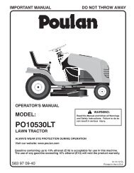
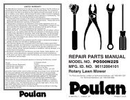
IMPORTANT MANUAL<br />
DO NOT THROW AWAY<br />
5000<br />
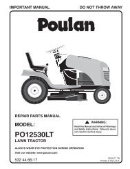
REPAIR PARTS MANUAL<br />
MODEL:<br />
<strong>PO175A42LT</strong><br />
LAWN TRACTOR<br />
WARNING:<br />
Read this Man u al and follow all Warnings<br />
and Safety Instructions. Fail ure to do so<br />
can re sult in serious in ju ry.<br />
ALWAYS WEAR EYE PROTECTION DURING OPERATION<br />
Visit our website: www.poulan.com<br />
<strong>09</strong>.28.11 BD<br />
532 44 67-46 Printed in the U.S.A.
HOW TO USE THIS MANUAL<br />
This manual is designed to provide the customer with a means to identify the parts on his/her tractor<br />
when ordering repair parts. The illustrations may or may not represent the actual assemblies; therefore,<br />
it is not recommended to use this manual as a guide to assemble or disassemble the tractor. Some<br />
hardware and parts are drawn larger in order to more readily identify them.<br />
Each tractor has its own model number.<br />
The model number for your tractor can be found on the fender under the seat.<br />
When ordering parts, always give the following information:<br />
• Product - “Tractor”<br />
• MODEL NUMBER - “<strong>PO175A42LT</strong> (96048002400)”<br />
• Part Number<br />
• Part Description<br />
TABLE OF CONTENTS<br />
SCHEMATIC ..................................................................................................................3<br />
ELECTRICAL ............................................................................................................. 4-5<br />
CHASSIS ................................................................................................................... 6-7<br />
DRIVE......................................................................................................................... 8-9<br />
ENGINE .................................................................................................................. 10-11<br />
STEERING ............................................................................................................. 12-13<br />
MOWER DECK ...................................................................................................... 14-15<br />
MOWER LIFT ...............................................................................................................16<br />
SEAT ............................................................................................................................17<br />
DECALS .......................................................................................................................18<br />
PARTS AND SERVICE ................................................................................................20<br />
2
TRACTOR - MODEL NO. <strong>PO175A42LT</strong> (96048002400), PRODUCT NO. 960 48 00-24<br />
SCHEMATIC<br />
SCH11<br />
RED<br />
A<br />
AMMETER<br />
(OPTIONAL)<br />
FUSE<br />
BATTERY<br />
RED<br />
SOLENOID<br />
BLACK<br />
STARTER<br />
M<br />
WHITE<br />
WHITE<br />
B<br />
S<br />
M<br />
G<br />
L<br />
A1<br />
A2<br />
ATTACHMENT CLUTCH<br />
(CLUTCH OFF)<br />
BLACK<br />
CLUTCH/BRAKE<br />
(PEDAL UP)<br />
GRAY<br />
BLACK<br />
REVERSE SWITCH<br />
(NOT IN REVERSE)<br />
BLACK<br />
BLACK<br />
BLACK<br />
BLACK<br />
2<br />
3<br />
1<br />
BLACK<br />
BLACK<br />
BLACK<br />
SEAT SWITCH<br />
(NOT OCCUPIED)<br />
6<br />
GRAY<br />
NOTE<br />
YOUR TRACTOR IS<br />
EQUIPPED WITH A SPECIAL<br />
ALTERNATOR SYSTEM.<br />
THE LIGHTS ARE NOT<br />
CONNECTED TO THE<br />
BATTERY, BUT HAVE THEIR<br />
OWN ELECTRICAL SOURCE.<br />
BECAUSE OF THIS, THE<br />
BRIGHTNESS OF THE LIGHTS<br />
WILL CHANGE WITH ENGINE<br />
SPEED. AT IDLE THE LIGHTS<br />
WILL DIM. AS THE ENGINE IS<br />
SPEEDED UP, THE LIGHTS<br />
WILL BECOME THEIR<br />
BRIGHTEST.<br />
BLACK<br />
BLACK /WHITE<br />
BLUE<br />
BLUE<br />
FUEL<br />
LINE<br />
FUEL SHUT-OFF<br />
SOLENOID<br />
(IF SO EQUIPPED)<br />
RED<br />
LIGHT SWITCH<br />
IGNITION<br />
UNIT<br />
(OPTIONAL)<br />
HOUR<br />
METER<br />
ORANGE<br />
JUNCTION<br />
CONNECTOR<br />
CHASSIS<br />
HARNESS<br />
CHARGING SYSTEM OUTPUT<br />
3 AMP DC @ 3600 RPM<br />
SPARK<br />
PLUGS GAP<br />
(2 PLUGS ON<br />
TWIN CYL. ENGINES)<br />
BLACK<br />
12V<br />
POWER OUTLET<br />
(OPTIONAL)<br />
SHORTING<br />
CONNECTOR<br />
LIGHTING SYSTEM OUTPUT<br />
5 AMP AC @ 3600 RPM ALTERNATOR<br />
DIODE<br />
28 VOLTS AC MIN. @ 3600 RPM<br />
(CHARGING SYSTEM DISCONNECTED)<br />
14 VOLTS AC MIN. @ 3600 RPM (LIGHTS OFF)<br />
BROWN<br />
BLACK<br />
IGNITION SWITCH<br />
HEADLIGHTS<br />
POSITION CIRCUIT<br />
OFF<br />
RUN/OVERRIDE<br />
M+G+A1<br />
B+A1<br />
RUN B+A1<br />
START B+S+A1<br />
“MAKE”<br />
L+A2<br />
3<br />
2<br />
1<br />
CHASSIS HARNESS<br />
CONNECTOR<br />
(MATING SIDE)<br />
6<br />
5<br />
4<br />
6 3<br />
5 2<br />
4<br />
1<br />
DASH HARNESS<br />
CONNECTOR<br />
(MATING SIDE)<br />
WIRING INSULATED CLIPS<br />
NOTE: IF WIRING INSULATED<br />
CLIPS WERE REMOVED FOR<br />
SERVICING OF UNIT, THEY<br />
SHOULD BE RE-INSTALLED TO<br />
PROPERLY SECURE YOUR<br />
WIRING.<br />
NON-REMOVABLE<br />
CONNECTIONS<br />
REMOVABLE<br />
CONNECTIONS<br />
3
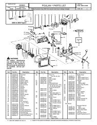
TRACTOR - MODEL NO. <strong>PO175A42LT</strong> (96048002400), PRODUCT NO. 960 48 00-24<br />
ELECTRICAL<br />
T06S<br />
With 12V Outlet Option<br />
103<br />
79<br />
22<br />
21<br />
30<br />
33<br />
87<br />
59<br />
With Service Minder Option<br />
34<br />
43<br />
27<br />
42<br />
46<br />
26<br />
40<br />
41<br />
25<br />
16<br />
90<br />
71<br />
2<br />
102<br />
29<br />
28 55<br />
105<br />
4
TRACTOR - MODEL NO. <strong>PO175A42LT</strong> (96048002400), PRODUCT NO. 960 48 00-24<br />
ELECTRICAL<br />
KEY PART<br />
NO. NO. DESCRIPTION<br />
1 532 16 34-65 Battery<br />
2 874 76 04-12 Bolt Hex Hd 1/4-20 unc x 3/4<br />
8 532 19 32-28 Box Battery<br />
16 532 17 61-38 Switch Interlock<br />
21 532 17 56-88 Harness Socket Light<br />
22 532 00 41-52 Bulb, Light #1156<br />
25 532 41 28-94 Cable Starter 6 Ga. BL/Red 14.5<br />
26 532 17 51-58 Fuse<br />
27 873 51 04-00 Nut Keps Hex 1/4-20 unc<br />
28 532 19 88-85 Cable Ground 18" Rear Battery Blk 6 Ga.<br />
29 532 19 27-49 Switch Seat<br />
30 532 19 33-50 Switch Ign<br />
33 532 41 19-35 Key/Chain<br />
34 532 11 07-12 Switch Light/Reset<br />
40 532 40 10-98 Harness Ign<br />
41 817 72 04-08 Screw 1/4-20 unc x 1/2<br />
42 532 13 15-63 Cover Terminal Red<br />
43 532 19 25-07 Solenoid<br />
55 817 06 05-12 Screw 5/16-18 x 3/4<br />
71 532 44 15-44 Harness Ign. Chass.<br />
79 532 17 52-42 Socket Asm. Bulb<br />
87 532 19 78-02 Switch Interlock Clutch<br />
90 532 43 53-95 Cover Terminal<br />
102 532 41 97-81 Pigtail Rev. GT Vatr.<br />
105 532 40 75-68 Switch Reverse<br />
NOTE: All component dimensions given in U.S. inches<br />
1 inch = 25.4 mm<br />
5
TRACTOR - MODEL NO. <strong>PO175A42LT</strong> (96048002400), PRODUCT NO. 960 48 00-24<br />
CHASSIS<br />
212<br />
29<br />
14<br />
18<br />
151<br />
176<br />
5<br />
137<br />
176<br />
182<br />
176<br />
177<br />
130<br />
175<br />
68<br />
235<br />
236<br />
150<br />
68<br />
34<br />
130<br />
235<br />
36<br />
176<br />
181<br />
196<br />
37<br />
194<br />
194<br />
183<br />
68<br />
183<br />
236<br />
68<br />
213<br />
138<br />
68<br />
218<br />
180<br />
68<br />
287<br />
162<br />
181<br />
189<br />
58<br />
228<br />
189<br />
217<br />
194<br />
52<br />
159<br />
189<br />
228<br />
189<br />
152<br />
189<br />
Chassis-tex_ALPHA_3<br />
159<br />
6
TRACTOR - MODEL NO. <strong>PO175A42LT</strong> (96048002400), PRODUCT NO. 960 48 00-24<br />
CHASSIS<br />
KEY PART<br />
NO. NO. DESCRIPTION<br />
5 532 41 17-64 Dash<br />
14 532 40 61-79 Hood<br />
18 532 42 67-41 Grille<br />
29 532 18 75-69 Insert Reflective<br />
34 532 19 61-25 Plate Engine<br />
36 817 06 05-12 Screw 5/16-18 x 3/4<br />
37 532 42 <strong>09</strong>-86 Fender<br />
52 873 68 05-00 Nut Crown Lock 5/16-18<br />
58 532 41 22-80 Drawbar Upper<br />
68 817 49 05-08 Screw Thdrol. 5/16-18 x 1/2<br />
130 532 41 63-58 Screw #10 x 0.750<br />
137 532 18 49-21 Bumper Hood<br />
138 532 40 97-30 Cupholder<br />
150 532 18 44-61 Duct Intake Air<br />
151 532 18 75-68 Bracket Pivot<br />
152 532 19 95-35 Shield Browning<br />
159 817 00 06-12 Screw 3/8-16 x 3/4<br />
162 532 14 24-32 Screw 1/4 x 1/2<br />
175 532 19 32-43 Crossmember<br />
176 532 40 07-76 Screw 10-24 x 5/8<br />
177 532 19 52-28 Bushing Steering<br />
180 532 41 50-63 Chassis<br />
181 532 40 30-25 Bushing Mtg. Fender Crgo.<br />
182 532 19 30-57 Dash Lower<br />
183 874 52 05-20 Bolt 5/16-18 x 1-1/4<br />
189 817 00 05-12 Screw 5/16-18 x 3/4<br />
194 873 90 05-00 Nut Lock Hex Flange 5/16-18<br />
196 532 41 45-79 Console Asm. Deck Lift<br />
212 532 19 54-02 Lens Bar<br />
213 874 76 05-12 Bolt Hex Hd. 5/16-18 unc x 3/4<br />
217 532 40 91-67 Rod Pivot Hood<br />
218 532 19 63-95 X-Piece Hood Stop<br />
228 532 19 51-61 Stud Fastener<br />
235 532 40 61-29 Spacer Fender<br />
236 873 93 05-00 Nut Lock 5/16-18<br />
287 817 60 04-06 Screw 1/4-20 x 3/8<br />
NOTE: All component dimensions given in U.S. inches<br />
1 inch = 25.4 mm<br />
7
TRACTOR - MODEL NO. <strong>PO175A42LT</strong> (96048002400), PRODUCT NO. 960 48 00-24<br />
DRIVE<br />
70<br />
185<br />
74<br />
56<br />
143<br />
184<br />
221<br />
42<br />
64<br />
35<br />
160<br />
203<br />
167<br />
160<br />
161<br />
299<br />
303<br />
303<br />
190<br />
49<br />
186<br />
189<br />
187<br />
50<br />
51<br />
131<br />
300<br />
188<br />
298<br />
302<br />
51<br />
52<br />
295<br />
165<br />
51<br />
301<br />
176<br />
174<br />
131<br />
305<br />
125<br />
172<br />
166<br />
51<br />
178<br />
175<br />
297<br />
233<br />
232<br />
116<br />
125<br />
22<br />
23<br />
125<br />
166<br />
1<br />
116<br />
73<br />
2<br />
205<br />
99<br />
37<br />
33<br />
73<br />
296 296<br />
drive-tex_VATR_6<br />
8
TRACTOR - MODEL NO. <strong>PO175A42LT</strong> (96048002400), PRODUCT NO. 960 48 00-24<br />
DRIVE<br />
KEY PART<br />
NO. NO. DESCRIPTION<br />
1 – – – – – – Transmission, Gentrans<br />
(415663) (Order parts<br />
from transaxle manufacturer.)<br />
2 532 12 35-83 Key.Square .2.0 x .1845/.1865<br />
22 532 42 10-63 Rod Shift<br />
23 532 10 69-33 Knob<br />
33 812 00 00-01 E-Ring. #5133-75<br />
35 532 19 77-22 Rod.Brake.Parking. Lt.Tex<br />
37 532 12 17-49 Washer.25/32 X 1 1/4 x 16 Ga.<br />
42 532 12 48-72 Cover.Pedal.Blk.Round<br />
49 872 11 06-14 Bolt.Rdhd.3/8-16Uncx1-3/4.Gr 5<br />
50 532 19 43-27 Idler.Flat.910"Offset<br />
51 873 90 06-00 Nut, Hex, Flangelock 3/8-16<br />
52 532 19 43-26 Idler.V-Groove.Offset<br />
56 532 19 72-53 Belt.Drive.100.97"<br />
64 532 19 62-00 Shaft Asm.Pedal.Brake Control<br />
70 532 44 03-23 Console<br />
73 874 49 05-44 Bolt.Hex.Flghd.5/16-18.Gr.5<br />
74 532 14 24-32 Screw.Hex.Wsh.Hi-Lo.1/4 x 1/2 unc<br />
99 532 42 73-40 Rod Bypass<br />
116 873 90 05-00 Nut, Lock Hex Flange 5/16-18 unc<br />
125 817 00 05-12 Screw.5/16-18 x 3/4.Smgml.Tap/Bl<br />
131 876 02 03-12 Pin Cotter 3/32/ x 3/4<br />
143 817 49 05-08 Screw.Thdrol.5/16-18 x 1/2 Tytt<br />
160 532 16 94-84 Retainer.Clip(M).Dia.290<br />
161 532 10 57-<strong>09</strong> Spring.Return.Clutch.6.75<br />
165 532 19 62-12 Bushing.Shaft.Brake.Hand Contr<br />
166 532 42 91-64 Nut Push .625<br />
167 532 40 52-57 Latch.Brake.Parking<br />
172 532 41 56-64 Strap Torque LH/RH<br />
174 532 19 72-89 Nut.Push..500<br />
KEY PART<br />
NO. NO. DESCRIPTION<br />
175 532 41 56-77 Shaft Asm Shift<br />
176 532 19 62-14 Arm.Clevis.Rod.Shift<br />
178 532 19 74-56 Spring.Shift.Gt.2006<br />
184 532 44 15-04 Handle.Parking Brake<br />
185 872 11 06-22 Bolt.Rdhd.3/8-16Unc x 2-3/4 Gr.5<br />
186 532 19 43-21 Spacer.Retainer<br />
187 819 13 32-10 Washer.13/32 x 2 x 10 Ga.<br />
188 532 19 43-23 Link.Clutch.Ground Drive<br />
189 532 19 43-17 Bellcrank.Groundrive.Nstg/Nstl<br />
190 532 19 43-18 Keeper.Bellcrank.Drive.Ground<br />
203 819 11 11-16 Washer 11/32 x 11/16 x 16 Ga.<br />
205 532 12 17-48 Washer.25/32 x 1-5/8 x 16Ga.<br />
221 532 40 31-87 Retainer.Spring.Clip.Handle<br />
232 874 78 07-16 Bolt.Fin Hex.7/16-14 x 1 Gr5<br />
233 532 40 52-96 Washer.Serrated<br />
295 532 42 03-06 Pin Clevis 183 Od x 1.260 Long<br />
296 532 42 04-71 Screw Thdrol 5/16-18 x 3<br />
297 532 42 02-23 Nut Push 1/4<br />
298 532 41 56-94 Pin Clevis Cbl. Brk. Variator<br />
299 532 41 56-83 Bracket Mount Idler<br />
300 532 41 56-81 Keeper Idler Rear<br />
301 532 41 56-80 Pulley Idler V-Groove<br />
302 532 41 56-66 Pulley Idler Flat 2.0 Od<br />
303 872 11 06-18 Bolt Rdhd Sgnk 3/8-16 x 2-1/4<br />
305 532 41 56-92 Cable Brake Variator<br />
NOTE: All component dimensions given in U.S. inches<br />
1 inch = 25.4 mm<br />
9
TRACTOR - MODEL NO. <strong>PO175A42LT</strong> (96048002400), PRODUCT NO. 960 48 00-24<br />
ENGINE<br />
1<br />
21<br />
20<br />
45<br />
84<br />
79<br />
18<br />
97<br />
122<br />
15<br />
96<br />
12<br />
69<br />
2<br />
37<br />
28<br />
42<br />
37<br />
90<br />
85<br />
29<br />
9<br />
OPTIONAL EQUIPMENT<br />
Spark Arrester<br />
engine-tex_BS_36<br />
10
TRACTOR - MODEL NO. <strong>PO175A42LT</strong> (96048002400), PRODUCT NO. 960 48 00-24<br />
ENGINE<br />
KEY PART<br />
NO. NO. DESCRIPTION<br />
1 – – – – – – Engine, B&S 31C707-3487-G1 (438654)<br />
(Order parts from engine manufacturer.)<br />
2 532 13 73-52 Muffler Exhaust B&S<br />
9 532 19 43-19 Keeper Belt<br />
12 532 40 19-85 Pulley Engine<br />
15 532 40 75-45 Tank Fuel Front<br />
18 532 43 02-20 Cap Asm Fuel<br />
20 532 17 05-51 Control Th/ch Flag<br />
21 817 72 04-08 Screw Hex Thd Cut 1/4-20 x 1/2<br />
28 532 40 11-37 Line Fuel<br />
29 532 13 71-80 Kit Spark Arrestor (Flat Scrn)<br />
37 532 12 34-87 Clamp Hose<br />
42 810 04 07-00 Washer Lock 7/16<br />
45 873 51 04-00 Nut Keps Hex 1/4-20 unc<br />
69 532 16 52-91 Gasket Eng 1 313 Id Tin Plated<br />
79 532 19 23-34 Screw Socket Head 5/16-18 x 3/4<br />
84 817 06 06-20 Screw 3/8-16 x 1-1/4<br />
85 532 17 39-37 Bolt Hex 7/16-20 x 4 Gr. 5-1.5 THR<br />
90 817 00 06-16 Screw 3/8-16 x 1<br />
96 819 <strong>09</strong> 14-16 Washer 9/32 x 7/8 x 16 Ga.<br />
97 817 67 04-12 Screw Thdrol 1/4-20 x 3/4<br />
122 532 42 19-22 Extension Drain Oil<br />
NOTE: All component dimensions given in U.S. inches<br />
1 inch = 25.4 mm<br />
For engine service and replacement parts, call the toll free<br />
number for your engine manufacturer listed below:<br />
Briggs & Stratton 1-800-233-3723<br />
Engine Power Rating Information<br />
The gross power rating for individual gas engine models is labeled in accordance with SAE (Society of Automotive Engineers)<br />
code J1940 (Small Engine Power & Torque Rating Procedure), and rating performance has been obtained and<br />
corrected in accordance with SAE J1995 (Revision 2002-05). Torque values are derived at 3060 RPM; horsepower values<br />
are derived at 3600 RPM. Actual gross engine power will be lower and is affected by, among other things, ambient operating<br />
conditions and engine-to-engine variability. Given both the wide array of products on which engines are placed and<br />
the variety of environmental issues applicable to operating the equipment, the gas engine will not develop the rated gross<br />
power when used in a given piece of power equipment (actual “on-site” or net power). This difference is due to a variety<br />
of factors including, but not limited to, accessories (air cleaner, exhaust, charging, cooling, carburetor, fuel pump, etc.),<br />
application limitations, ambient operating conditions (temperature, humidity, altitude), and engine-to-engine variability.<br />
Due to manufacturing and capacity limitations, Briggs & Stratton may substitute an engine of higher rated power for this<br />
Series engine.<br />
11
TRACTOR - MODEL NO. <strong>PO175A42LT</strong> (96048002400), PRODUCT NO. 960 48 00-24<br />
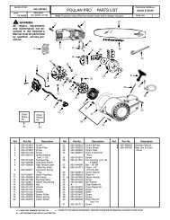
STEERING ASSEMBLY<br />
26<br />
72<br />
33<br />
45<br />
1<br />
20<br />
21<br />
71<br />
16<br />
13<br />
28<br />
64<br />
63<br />
57<br />
28<br />
60<br />
22<br />
57<br />
63<br />
8<br />
9<br />
7<br />
66<br />
74<br />
2<br />
67<br />
9<br />
8<br />
7<br />
19<br />
120<br />
121<br />
59<br />
6<br />
74<br />
74<br />
35<br />
58<br />
4<br />
67<br />
74<br />
6<br />
61<br />
68<br />
69<br />
14<br />
15<br />
70<br />
62<br />
14<br />
15<br />
5<br />
13<br />
13<br />
8<br />
steering-tex_STDHRR_2_r2<br />
53<br />
12
TRACTOR - MODEL NO. <strong>PO175A42LT</strong> (96048002400), PRODUCT NO. 960 48 00-24<br />
STEERING ASSEMBLY<br />
KEY PART<br />
NO. NO. DESCRIPTION<br />
1 532 42 45-43 Wheel, Steering<br />
2 532 41 81-68 Axle Asm., Front<br />
4 532 40 30-87 Spindle Asm., LH<br />
5 532 40 30-88 Spindle Asm., RH<br />
6 532 12 49-31 Washer Thrust 0.75 x 1.23<br />
7 532 12 17-48 Washer 25/32 x 1-5/8 x 16 Ga.<br />
8 812 00 00-29 Ring, Clip #T5304-75<br />
9 532 12 12-32 Cap, Spindle<br />
13 532 12 17-49 Washer 25/32 x 1-1/4 x 16 Ga.<br />
14 810 04 06-00 Washer Lock 3/8<br />
15 873 54 06-00 Nut, Crown Lock 3/8-24 unf<br />
16 532 42 93-74 Shaft Steering<br />
19 532 19 47-29 Plate Steering<br />
20 532 41 12-91 Boot Steering<br />
21 532 18 67-37 Adapter, Wheel Steering<br />
22 532 42 05-37 Strg. Supt. Lower<br />
26 532 42 46-91 Insert, Wheel Steering<br />
28 817 00 06-12 Screw 3/8-16 x 3/4<br />
33 810 04 05-00 Washer Lock 5/16<br />
35 532 19 47-32 Gear, Sector Plate<br />
45 819 11 38-12 Washer 11/32 ID x 2-3/8 OD x 12 Ga.<br />
53 532 18 89-67 Washer Hardened .793 x 1.637 x .060<br />
57 532 40 74-65 Bracket Upstop<br />
58 532 19 47-47 Bolt Shoulder Sector Pivot CFM<br />
59 532 19 47-48 Washer Thrust Sector Steering<br />
60 873 97 10-00 Nut Flange Lock 5/8-11<br />
61 532 19 47-40 Draglink, LH<br />
62 532 19 47-41 Draglink, RH<br />
63 817 00 05-12 Screw 5/16-18 x 3/4<br />
64 532 19 98-49 Retainer Clip Spring Steering<br />
66 871 02 07-48 Bolt Hex Fghd 7/16-14 x 3 Serr<br />
67 532 19 47-37 Bushing PM Front Axle<br />
68 873 90 07-00 Nut Lock Flange 7/16-14 Gr. 5<br />
69 532 19 91-62 Washer 1.5 x .505 x .118<br />
70 532 19 61-97 Bracket Deck Susp. Front<br />
71 532 19 07-52 Shaft Extension Steering<br />
72 532 42 89-82 Bolt Fin Hx 5/16-18 x 4 w/Patch<br />
74 532 12 49-37 Bearing Col. Strg.<br />
120 532 41 56-89 Bracket Locator<br />
121 817 49 05-08 Screw 5/16-18 x 1/2<br />
NOTE: All component dimensions given in U.S. inches<br />
1 inch = 25.4 mm<br />
13
TRACTOR - MODEL NO. <strong>PO175A42LT</strong> (96048002400), PRODUCT NO. 960 48 00-24<br />
MOWER DECK<br />
70<br />
67<br />
195<br />
122<br />
152<br />
7<br />
37<br />
7<br />
68<br />
123<br />
195<br />
57<br />
40<br />
42<br />
43<br />
145<br />
59<br />
30<br />
56<br />
60<br />
57<br />
55<br />
46<br />
38<br />
47<br />
192<br />
113<br />
64<br />
30<br />
40<br />
36<br />
144<br />
56<br />
34<br />
63<br />
147<br />
30<br />
38<br />
33<br />
32<br />
208<br />
31<br />
30<br />
1<br />
21<br />
62<br />
21<br />
23<br />
24 25<br />
188<br />
189<br />
69<br />
21<br />
26<br />
19<br />
6<br />
113<br />
189<br />
29<br />
188<br />
15<br />
6<br />
19<br />
14<br />
20<br />
13<br />
69<br />
27<br />
11<br />
69<br />
42_D_man-tex_LT_32_r1<br />
8<br />
14
TRACTOR - MODEL NO. <strong>PO175A42LT</strong> (96048002400), PRODUCT NO. 960 48 00-24<br />
MOWER DECK<br />
KEY PART<br />
NO. NO. DESCRIPTION<br />
1 532 19 99-11 Mower Housing<br />
6 532 19 51-86 Arm Suspension<br />
7 532 41 63-58 Screw #10 x 0.750 BOS Thread<br />
8 532 19 30-03 Bolt/Washer Asm 7/16-20 unf<br />
11 532 13 89-71 Blade, 42" Hi-Lift<br />
(For bagging or discharge)<br />
13 532 19 28-72 Shaft Assembly, Mandrel<br />
14 532 18 72-81 Housing, Mandrel<br />
15 532 11 04-85 Bearing, Ball, Mandrel<br />
19 532 19 65-39 Bolt, Shoulder<br />
20 532 15 97-70 Baffle, Vortex<br />
21 873 68 05-00 Nut, Crownlock 5/16-18 unc<br />
23 532 19 25-57 Bracket, Deflector<br />
24 532 10 53-04 Cap, Sleeve<br />
25 532 19 70-26 Spring, Torsion, Deflector<br />
26 532 11 04-52 Nut, Push<br />
27 532 40 30-04 Shield, Deflector<br />
29 532 13 14-91 Rod, Hinge<br />
30 532 17 39-84 Screw Thdrol Rolling Wsh Hd<br />
31 532 18 76-90 Washer, Spacer<br />
32 532 19 74-73 Pulley, Mandrel<br />
33 532 40 02-34 Nut, Toplock, Flanged<br />
34 872 11 06-12 Bolt Carr Sh. 3/8-16 x 1-1/2 Gr. 5<br />
36 532 19 73-79 Pulley, Idler 4.50 RAW<br />
37 819 13 13-16 Washer 13/32 x 13/16 x 16 Ga.<br />
38 532 43 25-20 Keeper Belt Mandrel<br />
40 873 90 06-00 Nut, Lock Flg. 3/8-16 unc<br />
42 532 19 84-10 Spring Torsion Brake<br />
43 532 19 72-56 Spring Torsion Retainer<br />
46 532 13 77-29 Screw Thd Roll 1/4-20 x 5/8<br />
47 532 19 72-50 Bracket Clutch Cable<br />
55 532 43 71-10 Arm, Idler<br />
KEY PART<br />
NO. NO. DESCRIPTION<br />
56 532 19 90-92 Spacer, Retainer<br />
57 817 00 06-16 Screw Hexwsh Thd 3/8-16 x 1<br />
59 532 14 10-43 Guard, Tuv Idler (94)<br />
60 532 19 72-61 Arm Brake Mower<br />
62 872 11 06-16 Bolt Rdhd Sqnk 3/8-16 unc x 2<br />
63 532 19 94-77 Arm Brake Mower<br />
64 532 19 97-90 Linkage Brake<br />
67 532 40 30-12 Handle, Clutch Cable<br />
68 532 42 96-36 V-Belt<br />
69 872 14 05-05 Bolt Rdhd Sqnk 5/16-18 x 5/8<br />
70 532 19 83-32 Clutch Asm. Manual<br />
113 817 00 05-10 Screw 5/16-18<br />
122 532 19 72-58 Keeper Belt Eng. LH<br />
123 532 19 72-59 Keeper Belt Eng. RH<br />
144 532 19 92-04 Keeper Belt<br />
145 532 19 31-97 Pulley Idler Primary<br />
147 532 40 19-71 Spring Return<br />
152 532 43 51-11 Cable Clutch Manual w/Spr.<br />
188 532 19 51-61 Stud Fastener<br />
189 873 90 05-00 Nut Lock Hex Flange<br />
192 532 19 72-60 Bracket Brake Stand LH<br />
195 817 00 06-12 Screw Hexwsh Thdr 3/8-16 x 3/4<br />
208 817 67 06-08 Screw Thdrol 3/8-16 x 1/2<br />
- - 532 19 28-70 Mandrel Assembly (Includes<br />
housing, shaft assembly, and<br />
bearing only - pulley/nut/washer<br />
and blade bolt/washers not included)<br />
- - 532 41 52-41 Replacement Mower, Complete<br />
NOTE: All component dimensions given in U.S. inches<br />
1 inch = 25.4 mm<br />
15
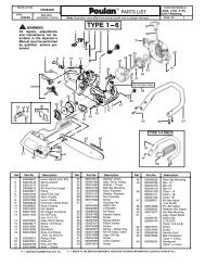
TRACTOR - MODEL NO. <strong>PO175A42LT</strong> (96048002400), PRODUCT NO. 960 48 00-24<br />
MOWER LIFT<br />
7<br />
87<br />
90 98<br />
10<br />
89<br />
3<br />
97<br />
100<br />
2<br />
91<br />
88<br />
97<br />
87<br />
89<br />
101*<br />
89<br />
87<br />
lift-tex_17_r3 *Key 91 may be substituted for Key 101<br />
KEY PART<br />
NO. NO. DESCRIPTION<br />
2 532 42 20-27 Shaft Asm., Cross Lift<br />
3 532 19 52-31 Lever Asm., Lift RH<br />
7 532 41 15-55 Grip, Lever<br />
10 532 19 63-14 Spring Torsion<br />
87 532 19 42-<strong>09</strong> Pin Cotter 7/16 Bow Tie Lock<br />
88 532 41 07-10 Spring Lift Assist<br />
89 819 19 19-12 Washer Clear Zinc<br />
90 532 19 42-08 Pin Cotter 5/16 Bow Tie Lock<br />
KEY PART<br />
NO. NO. DESCRIPTION<br />
91 532 19 51-81 Link Lift Susp Mower Rear<br />
97 817 00 06-12 Screw 3/8-16 x .75 Smgml Tap/R.Z<br />
98 532 19 52-70 Link Lift Susp. Front Mower<br />
100 873 93 06-00 Nut Centerlock 3/8 -16 unc<br />
101 532 40 70-03 Link Asm. Lift Fixed<br />
NOTE: All component dimensions given in U.S. inches<br />
1 inch = 25.4 mm<br />
16
TRACTOR - MODEL NO. <strong>PO175A42LT</strong> (96048002400), PRODUCT NO. 960 48 00-24<br />
SEAT ASSEMBLY<br />
1<br />
8<br />
7<br />
8<br />
8<br />
7<br />
8<br />
14<br />
10<br />
16<br />
15<br />
42<br />
12<br />
19<br />
21<br />
6<br />
6<br />
37<br />
5<br />
37<br />
21<br />
13<br />
17<br />
2<br />
3<br />
seat-tex_knob_3<br />
KEY PART<br />
NO. NO. DESCRIPTION<br />
1 532 40 30-17 Seat<br />
2 532 18 01-66 Bracket Pivot Fender<br />
3 532 14 06-75 Strap, Asm Fender<br />
5 532 14 50-06 Clip Push-in Hinged<br />
6 873 80 06-00 Nut, Lock w/Ins. 3/8-16 unc<br />
7 532 12 41-81 Spring, Seat Cprsn<br />
8 532 17 18-77 Bolt 5/16-18 unc x 3/4 w/Sems<br />
10 532 44 18-05 Pan, Seat<br />
12 532 19 93-70 Bracket Mnt.<br />
13 532 12 12-48 Bushing Snap<br />
14 872 05 04-12 Bolt 1/4-20 x 1-1/2<br />
KEY PART<br />
NO. NO. DESCRIPTION<br />
15 532 13 43-00 Spacer Split<br />
16 532 12 37-40 Spring CPRSN Plate<br />
17 532 12 39-76 Nut Lock 1/4<br />
19 532 19 93-72 Knob Seat<br />
21 532 17 18-52 Bolt, Shoulder 5/16-18<br />
37 873 80 05-00 Nut, Lock 5/16-18 unc<br />
42 532 19 93-71 Cup Washer<br />
NOTE: All component dimensions given in U.S. inches<br />
1 inch = 25.4 mm<br />
17
TRACTOR - MODEL NO. <strong>PO175A42LT</strong> (96048002400), PRODUCT NO. 960 48 00-24<br />
DECALS<br />
7 12 12<br />
2<br />
6 15<br />
9<br />
5<br />
4<br />
1<br />
5<br />
3 8<br />
KEY PART<br />
NO. NO. DESCRIPTION<br />
1 532 44 68-01 Decal, Fender RH/LH Set<br />
2 532 44 66-06 Decal, Replacement<br />
3 532 43 10-92 Decal, Engine HP<br />
4 532 17 05-63 Decal, Warning<br />
5 532 43 20-72 Decal, Dash Lower<br />
6 532 41 16-58 Decal, Fender Warning (E&F)<br />
7 532 43 19-82 Decal, Ins Str Wh<br />
8 532 43 52-86 Dceal, Warn. Spark<br />
9 532 43 19-86 Decal, Fender<br />
10<br />
1<br />
KEY PART<br />
NO. NO. DESCRIPTION<br />
10 532 16 03-96 Decal, V-Belt Sch.<br />
12 532 43 19-83 Decal, Hood RH/LH<br />
15 532 14 50-05 Decal, Caution, Battery<br />
- - 532 16 69-60 Decal, Bypass<br />
- - 532 40 95-05 Pad Footrest LH<br />
- - 532 41 12-73 Pad Footrest RH<br />
- - 532 44 67-45 Manual, Operator's, (English/French)<br />
- - 532 44 67-46 Manual, Parts,(English /French)<br />
WHEELS & TIRES<br />
1<br />
2<br />
5,8<br />
7<br />
6<br />
4,10<br />
3,9<br />
11<br />
KEY PART<br />
NO. NO. DESCRIPTION<br />
1 532 05 91-92 Cap, Tire Valve<br />
2 532 06 51-39 Stem, Valve<br />
3 532 10 62-22 Tire, Front<br />
4 532 05 99-04 Tube, Front (Service item only)<br />
5 532 18 33-37 Rim Assembly, 6" Front<br />
6 532 12 49-57 Fitting, Grease (Front wheel only)<br />
7 532 12 49-59 Bearing, Flange (Front wheel<br />
only)<br />
8 532 19 33-38 Rim Assembly, 8" Rear<br />
9 532 42 05-31 Tire, Rear<br />
10 532 12 49-26 Tube, Rear (Service item only)<br />
11 532 17 50-39 Cap, Hub Axle<br />
- - 532 14 43-34 Sealant, Tire (10 oz. Tube)<br />
wheel_1<br />
18
SERVICE NOTES<br />
19
PARTS AND SERVICE<br />
This product has been expertly en gi neered and carefully manu fac tured to rigid quality stan dards. As with all mechanical<br />
products, some adjustments or part replacement may be necessary during the life of your unit.<br />
For Parts and service, contact our authorized distributor: call 1-800-849-1297<br />
• For replacement parts, have available the following information:<br />
a. Model Number/Manufacturer's I.D. Number<br />
b. Description of part.<br />
For Technical Assistance: call 1-800-829-5886<br />
For a Parts Manual, go to our website: www.poulan.com<br />
NOTE:<br />
HOP provides parts and service through its au thor ized dis tribu tors and dealers; there fore, all<br />
requests for parts and service should be directed to your local dealer(s). The phi loso phy of HOP<br />
is to con tinu ally improve all of its prod ucts. If the operating characteristics or the appearance<br />
of your product differs from those described in this Manual, please contact your local dealer<br />
for updated in for ma tion and as sis tance.<br />
20