AC Induction Motor Slip â What It Is And How To ... - Power/mation
AC Induction Motor Slip â What It Is And How To ... - Power/mation
AC Induction Motor Slip â What It Is And How To ... - Power/mation

Create successful ePaper yourself
Turn your PDF publications into a flip-book with our unique Google optimized e-Paper software.
<strong>AC</strong> <strong>Induction</strong> <strong>Motor</strong> <strong>Slip</strong> – <strong>What</strong> <strong>It</strong> <strong>Is</strong> <strong>And</strong> <strong>How</strong> <strong>To</strong> Minimize <strong>It</strong><br />
Mauri Peltola, ABB Oy, Helsinki, Finland<br />
The alternating current (<strong>AC</strong>) induction motor is often referred to as the workhorse of the industry<br />
because it offers users simple, rugged construction, easy maintenance and cost-effective pricing.<br />
As a result of these factors, more than 90 percent of motors installed worldwide are <strong>AC</strong> induction.<br />
Despite its popularity, the <strong>AC</strong> induction motor has two limitations: <strong>It</strong> is not a constant-speed<br />
machine, and it is not inherently capable of providing variable-speed operation. Both limitations<br />
require consideration, as the quality and accuracy requirements of motor/drive applications<br />
continue to increase.<br />
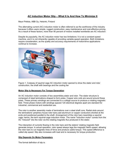
Figure 1. Cutaway of squirrel cage <strong>AC</strong> induction motor opened to show the stator and rotor<br />
construction, the shaft with bearings and the cooling fan<br />
<strong>Motor</strong> <strong>Slip</strong> <strong>Is</strong> Necessary For <strong>To</strong>rque Generation<br />
An <strong>AC</strong> induction motor consists of two assemblies,stator and rotor. The stator structure is<br />
composed of steel laminations shaped to form poles. Copper wire coils are wound around these<br />
poles. These primary windings are connected to a voltage source to produce a rotating magnetic<br />
field. Three-phase motors with windings spaced 120 electrical degrees apart are standard for<br />
industrial, commercial and residential use.<br />
The rotor is another assembly made of laminations over a steel shaft core. Radial slots around<br />
the laminations' periphery house rotor bars,cast-aluminum or copper conductors shorted at the<br />
ends and positioned parallel to the shaft. Arrangement of the rotor bars resembles a squirrel<br />
cage; hence, the term squirrel-cage induction motor. The name "induction motor" comes from the<br />
<strong>AC</strong> "induced" into the rotor via the rotating magnetic flux produced in the stator.<br />
The interaction of currents flowing in the rotor bars and the stators' rotating magnetic field<br />
generate torque. In actual operation, rotor speed always lags the magnetic field's speed, allowing<br />
the rotor bars to cut magnetic lines of force and produce useful torque. This speed difference is<br />
called slip speed. <strong>Slip</strong> also increases with load and is necessary for torque production.<br />
<strong>Slip</strong> Depends On <strong>Motor</strong> Parameters<br />
The formal definition of slip is:
S = (ns , n) x 100 percent/ns , where<br />
ns = synchronous speed<br />
n = actual speed<br />
At low values, slip is directly proportional to the rotor resistance, stator voltage frequency and<br />
load torque, and inversely proportional to the second power of supply voltage. The traditional way<br />
to control wound-rotor-induction-motor speed is to increase slip by adding resistance in the rotor<br />
circuit. The slip of low-hp motors is higher than that of high-hp motors because rotor-winding<br />
resistance is greater in smaller motors.<br />
As seen in Table 1, smaller and lower-speed motors are associated with higher relative slip.<br />
<strong>How</strong>ever, high-slip large motors and low-slip small motors also are available.<br />
Table 1. <strong>Motor</strong> slip of selected aluminium and cast iron NEMA motors, with synchronous speed<br />
ranging from 3600 RPM to 900 RPM<br />
As one can see, full-load slip varies from less than 1 percent (in high-hp motors) to more than 5<br />
percent (in fractional-hp motors). These variations may cause load-sharing problems when<br />
motors of different sizes are connected mechanically. At low load, the sharing is about correct;<br />
but at full load, the motor with lower slip takes a higher share of the load than the motor with<br />
higher slip.<br />
As shown in Figure 2, rotor speed decreases in proportion to load torque. This means that rotor<br />
slip increases in the same proportion.<br />
Key:<br />
A = Synchronous speed<br />
B = Rotor speed<br />
C = Rotor slip
D = <strong>To</strong>rque<br />
Figure 2. The speed curve of an induction motor. <strong>Slip</strong> is the difference in rotor speed relative to<br />
that of the synchronous speed. CD = AD , BD = AB.<br />
Relatively high rotor impedance is required for good across-the-line (full voltage) starting<br />
performance (meaning high torque against low current), and low rotor impedance is necessary for<br />
low full-load speed slip and high operating efficiency. The curves in Figure 3 show how greater<br />
rotor impedance in motor B reduces the starting current and increases the starting torquebut it<br />
causes a greater slip than in standard motor A.<br />
Figure 3. <strong>To</strong>rque/speed and current/speed curves for a standard motor A (full lines) and a hightorque<br />
motor B (dotted lines).<br />
Methods <strong>To</strong> Reduce <strong>Slip</strong><br />
Synchronous motors, reluctance motors or permanent-magnet motors don't slip. Synchronous<br />
motors commonly are used for very high-power and very low-power applications, but to a lesser<br />
extent in the medium-hp range, where many typical industrial applications are found. Reluctance
motors also are used, but their output/weight ratio is not good and, therefore, they are less<br />
competitive than squirrel-cage induction motors.<br />
Permanent magnet (PM) motors, which are used with electronic adjustable-speed drives, provide<br />
benefits such as accurate speed control without slip, high efficiency with low rotor losses and the<br />
flexibility of choosing a very low base speed, eliminating the need for gearboxes. PM motors are<br />
limited to special applications, mainly because of high cost and the lack of standardization.<br />
Figure 4. The effect of the slip compensation.<br />
Selecting an oversized <strong>AC</strong> induction motor also reduces slip. Larger motors exhibit less slip, and<br />
it gets smaller with a partial (rather than full) motor load.<br />
For example, refer to Table 1. The required power is 10 hp at about 1,800 rpm and 1.5 percent<br />
speed accuracy is required. We know that a 10-hp motor has a slip of 4.4 percent. Can we<br />
achieve an accuracy of 1.5 percent with a 15-hp motor?<br />
Answer: The full-load slip of the 15-hp motor is 2.2 percent, but the load is only 10/15 = 0.67. The<br />
slip will be 67 percent of 2.2 and equals 1.47 percent, which fulfils the requirements. A<br />
disadvantage to oversizing is that larger motors consume more energy, increasing investment<br />
and operation costs.<br />
Applying An Adjustable-Speed <strong>AC</strong> Drive <strong>Is</strong> Often The Best Solution<br />
Using adjustable-speed control can solve <strong>AC</strong> induction motor limitations. The most common <strong>AC</strong><br />
drives use pulse-width modulation (PWM). Line voltage is rectified, filtered and converted to a<br />
variable voltage and frequency. When frequency-converter ouput is connected to an <strong>AC</strong> motor,<br />
it's possible to adjust motor speed.<br />
When an <strong>AC</strong> drive is used to adjust motor speed, motor slip is no longer a problem in many<br />
applications. A number of drive applications still exist, including printing machines, extruders,<br />
paper machines, cranes and elevators, in which high static speed accuracy, dynamic speed<br />
accuracy or both are required.
Rather than over sizing the motors to eliminate the slip-induced speed error, it may be better to<br />
use sectional drive line-ups with separate inverters for each motor. The inverters are connected<br />
to a direct current (DC)-voltage bus bar supplied by a common rectifier. This is an energy-efficient<br />
solution because the driving sections use the braking energy from decelerating sections<br />
(regeneration).<br />
<strong>To</strong> reduce motor slip, compensation can be added to <strong>AC</strong> drives. A load torque signal is added to<br />
the speed controller to increase the output frequency in proportion to the load. (<strong>Slip</strong> compensation<br />
cannot be 100 percent of the slip because rotor temperature variations cause over-compensation<br />
and unstable control.) But the compensation can achieve an accuracy as great as 80 percent,<br />
reducing slip from 2.4 percent to 0.5 percent.<br />
Figure 5. Block diagram of Direct <strong>To</strong>rque Control, DTC<br />
Vector <strong>And</strong> Direct <strong>To</strong>rque Control Improve Speed Control<br />
The newest high-performance technologies in adjustable-speed drives field are vector control and<br />
direct torque control (DTC). Both use some type of motor model and suitable control algorithms to<br />
control torque and flux, rather than the voltage and frequency parameters used in PWM drives.<br />
The difference between traditional vector control and DTC is that the latter has no fixed switching<br />
pattern for each voltage cycle. DTC switches, instead, the inverter according to the load 40,000<br />
times per sec. This makes DTC especially fast during instant load changes and minimizes the<br />
need for and effect of dramatic speed changes once the load or process is in operation.<br />
<strong>What</strong> <strong>Is</strong> DTC?<br />
DTC is an optimized <strong>AC</strong> drives control principle, in which inverter switching directly controls flux<br />
and motor torque.<br />
The input variables for DTC are motor current and DC link and voltage. The voltage is defined<br />
from the DC-bus voltage and inverter switch positions. The voltage and current signals are inputs<br />
to an accurate motor model, which updates stator flux and torque every 25 microseconds.
Two-level motor torque and flux comparators compare the actual values to the reference values<br />
produced by torque and flux reference controllers. The outputs from these two-level controllers<br />
are updated every 25 microseconds, and they indicate whether the torque or flux must be<br />
changed.<br />
Depending on the outputs from the two-level controllers, the switching logic optimizes inverter<br />
switch positions. This means that each single voltage pulse is determined separately at "atomic<br />
level." The inverter switch positions determine motor voltage and current, which, in turn, influence<br />
the motor torque and flux (this closed loop control eliminates the need for encoders in many<br />
applications).<br />
The reason DTC control reacts faster than PWM control is shown in Figure 6. The motor is<br />
running with low load at point A and the load has a stepwise increase to high load. The higher<br />
torque with the PWM control is achieved by reducing speed from A to B, which is quite slow. The<br />
higher torque with the DTC control is achieved by direct increase of torque from A to C about 10<br />
times faster than that of PWM control.<br />
Figure 6. Comparison between PWM modulation and DTC drive control during load impact: A to<br />
B with PWM control and A to C with DTC control.<br />
<strong>Slip</strong> compensation with DTC is instantaneous and produces a nominal slip of 10 percent. This<br />
translates into a speed accuracy of 0.1 percent to 0.5 percent. This enables DTC drive use in<br />
many applications where a tachometer-based vector control was needed previously. For<br />
applications demanding an even higher accuracy, it's possible to add a pulse encoder to a DTC<br />
drive.<br />
Mauri Peltola is the former marketing manager of ABB Oy, Drives in Helsinki, Finland. He can be<br />
reached at Mauri.Peltola@fi.abb.com.