SenseAir S8 - Sensor + Test
SenseAir S8 - Sensor + Test
SenseAir S8 - Sensor + Test

You also want an ePaper? Increase the reach of your titles
YUMPU automatically turns print PDFs into web optimized ePapers that Google loves.
Driesen + Kern GmbH<br />
Absolute maximum ratings<br />
Stress greater than those listed in Table II may cause permanent damage to the device. These ratings<br />
are stress ratings only. Operation of the device at any condition outside those indicated in the<br />
operational section of these specifications is not implied. Exposure to absolute maximum rating for<br />
extended periods may affect device reliability.<br />
Parameter Minimum Maximum Units Notes<br />
Ambient temperature under bias -40 85 C<br />
Voltage on G+ pin with respect to G0 pin -0.3 5.5 V 1,2<br />
Maximum output current from active output pin -25 +25 mA 1<br />
Maximum current on input -5 +5 uA 1<br />
Maximum voltage on UART lines, PWM and bCAL_in - 0.3 DVCC_out + 0.5 V 1<br />
Maximum voltage on Alarm OC - 0.3 G+ V 1,3<br />
Table 2. Absolute maximum ratings specification for the <strong>SenseAir</strong> ® <strong>S8</strong><br />
__________________________________________________________________________________________<br />
Note 1:<br />
Note 2:<br />
Note 3:<br />
Specified parameter relies on specification of subcontractor and is not tested by <strong>SenseAir</strong><br />
Refer chapter “Terminal Description” for rated voltage information<br />
Alarm_OC pin is internally pulled up to G+. External pull up to higher voltage will provide resistive divider powering<br />
sensor via high resistance.<br />
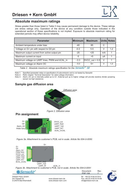
Sample gas diffusion area<br />
Diffusion area<br />
Pin assignment<br />
Figure 2. Diffusion area<br />
G+<br />
G0<br />
Alarm_OC<br />
PWM 1kHz<br />
DVCC_out<br />
UART_RxD<br />
UART_TxD<br />
UART_R/T<br />
bCAL_in/CAL<br />
Figure 3a. Attachment to customer’s PCB, not in scale. Article No 004-0-0050<br />
G+<br />
G+<br />
G0<br />
Alarm_OC<br />
PWM 1kHz<br />
DVCC_out<br />
UART_RxD<br />
UART_TxD<br />
UART_R/T<br />
BCAL_in/CAL<br />
UART_RxD<br />
UART_TxD<br />
UART_R/ bCAL_in<br />
Figure 3b. Attachment to customer’s PCB, not in scale. Article No 004-0-0051<br />
Driesen+Kern GmbH<br />
Am Hasselt 25<br />
D-24576 Bad Bramstedt<br />
Document<br />
PSP 108<br />
Rev<br />
7<br />
Tel. +49 (0) 4192 8170-0<br />
www.driesen-kern.de Fax +49 (0) 4192 8170-99<br />
www.driesen-kern.com<br />
info@driesen-kern.de<br />
Page<br />
4 (10)