PSU Manual - Rosco Laboratories
PSU Manual - Rosco Laboratories
PSU Manual - Rosco Laboratories

You also want an ePaper? Increase the reach of your titles
YUMPU automatically turns print PDFs into web optimized ePapers that Google loves.
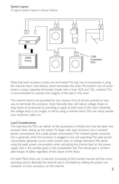
System Layout<br />
A typical system layout is shown below.<br />
Note that both accessory chains are terminated.The top row of accessories is using<br />
the channel return (see below), which terminates the chain.The bottom row of accessories<br />
is using a separate terminator (made with a 4-pin XLR and 120_ resistor).This<br />
is recommended to maintain the integrity of the data in the chain.<br />
The channel returns are provided for two reasons. First of all, they provide an easy<br />
way to terminate the accessory chain. Secondly, they will reduce voltage drops on<br />
long chains of accessories by providing a supply at both ends of the chain. Generally<br />
the voltage drop is cut roughly in half by using a channel return.This can nearly double<br />
your maximum cable run.<br />
Load Considerations<br />
The load that the <strong>PSU</strong> can deliver to the accessories is limited and must be taken into<br />
account when setting up the system.To begin with, each accessory has a constant<br />
power consumption and a peak power consumption.The constant power consumption<br />
is generally when the accessory is plugged in, but not operating.The peak power<br />
consumption generally occurs when motors start or change directions. We advise<br />
using the peak power consumption when calculating the channel load on the power<br />
supply (this is the number given in the compatibility list).This should give a comfortable<br />
margin of safety regardless of the nature of the show.<br />
On both <strong>PSU</strong>s, there are 4 channels (consisting of the marked channel and the corresponding<br />
return). Basically, the channel load is calculated by adding the power consumption<br />
of every accessory on the channel.<br />
3