OMD-2005 - Deckma Hamburg Gmbh
OMD-2005 - Deckma Hamburg Gmbh
OMD-2005 - Deckma Hamburg Gmbh

Create successful ePaper yourself
Turn your PDF publications into a flip-book with our unique Google optimized e-Paper software.
INSTRUCTION MANUAL<br />
15ppm Bilge Alarm<br />
Type <strong>OMD</strong>-<strong>2005</strong><br />
DECKMA HAMBURG GmbH<br />
Kieler Straße 316, D-22525 <strong>Hamburg</strong> - Germany<br />
Tel.: +49 (0) 40 54 88 76-0, Fax: +49 (0) 40 54 88 76-10<br />
Internet: www.deckma.com eMail: post@deckma.com
DECKMA HAMBURG GmbH<br />
IMPORTANT NOTICE<br />
Replacement components for 15ppm Bilge Alarms.<br />
General<br />
All monitors in our range are inspected and tested to the related I.M.O. requirements at<br />
our factories prior to delivery.<br />
In normal use the units should operate correctly and without fault over a long period of<br />
time requiring only small amounts of maintenance to be carried out as outlined in the<br />
instruction manuals.<br />
Service Exchange Units<br />
In the event of a monitor malfunction due to electrical or electronic component failure it<br />
is our recommendation that a service exchange unit be ordered.<br />
The defective instrument should be returned to our works within 30 days of supplying<br />
the service exchange unit, then only the repair charge is payable. Otherwise the whole<br />
cost of a service exchange unit becomes payable.<br />
This procedure is by far the easiest and most cost effective way of ensuring the monitor<br />
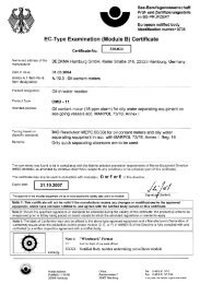
on board conforms to I.M.O. resolution MEPC.107 (49).<br />
Remark:<br />
According the MEPC.107(49) § 4.2.11 the unit has to be checked at IOPP Certificate<br />
renewal survey by the manufacturer or persons authorized by the manufacturer.<br />
Alternatively the unit may be replaced by a calibrated 15 ppm Bilge Alarm. The <strong>OMD</strong>-<br />
<strong>2005</strong> is designed in that way, that only the measuring cell needs to be changed, as this<br />
unit carry the calibration onboard. The Calibration Certificate with the date of the last<br />
calibration check should be retained onboard for inspection purposes.<br />
If for some reasons the computer unit needs to be changed, it has to make sure, that<br />
the memory card will remain on board for at least 18 month. The new computer unit will<br />
carry its own memory card. The old card can be insert into the new unit only for reading.<br />
Writing is only possible with the card delivered with the new computer unit. For details<br />
see section 13.1.<br />
Warranty<br />
Our warranty terms are12 months after installation but maximal 18 months after delivery<br />
ex works. The maker undertakes to remedy any defect resulting from faulty materials of<br />
workmanship except wearing parts.<br />
The maker's obligation is limited to the repairs or replacement of such defective parts by<br />
his own plant or one of his authorized service stations.<br />
The purchaser shall bear the cost and risk of transport of defective parts and repaired<br />
parts supplied in replacement of such defective parts.<br />
ANY DISMANTLING OR BREAKING OF A SEAL WILL VOID THE WARRANTY<br />
Issue: 27.05.08 Instruction Manual <strong>OMD</strong>-<strong>2005</strong> Page 2 of 25
DECKMA HAMBURG GmbH<br />
CONTENTS<br />
SECTION TITLE PAGE<br />
1.0 Introduction 4<br />
2.0 Important Notes 4<br />
3.0 Principle of Operation 4<br />
3.1 Measuring Principle 4<br />
3.2 Features 5<br />
3.3 Adjustment 5<br />
3.4 Displays and Alarms 5<br />
4.0 Specification 7<br />
5.0 Construction 8<br />
6.0 Installation 9<br />
7.0 Piping 10<br />
8.0 Wiring 11<br />
8.1 Typical Control System 13<br />
9.0 Power Supply 13<br />
10.0 Commissioning 13<br />
10.1 Electrical 13<br />
10.2 Piping 13<br />
10.3 Functional Tests 14<br />
10.4 Programming Mode 15<br />
11.0 Operating Instructions 17<br />
11.1 Operator Notes 18<br />
12.0 Operator Maintenance 18<br />
12.1 Manual Cell Clean Unit 19<br />
13.0 Fault Finding 20<br />
13.1 Memory Card 22<br />
14.0 Calibration 23<br />
14.1 Calibration and Repeatability Check 23<br />
15.0 Spare Parts 24<br />
15.1 Recommended On Board Spares 24<br />
16.0 Remarks 25<br />
Issue: 27.05.08 Instruction Manual <strong>OMD</strong>-<strong>2005</strong> Page 3 of 25
1.0 INTRODUCTION<br />
DECKMA HAMBURG GmbH<br />
The <strong>OMD</strong>-<strong>2005</strong> Bilge Alarm Unit has been designed specifically for use in<br />
conjunction with 15 ppm oil-water separator units and has a specification and<br />
performance which exceeds the requirements of the International Maritime<br />
Organization specifications for 15ppm Bilge Alarms contained in Resolution<br />
MEPC. 107 (49).<br />
The unit is supplied with 2 works-adjusted alarms at 15 ppm. Other set points<br />
(10 ppm or 5 ppm) are possible and can be adjusted on site at any time by using<br />
the buttons at the front panel.<br />
If an alarm set point is exceed, the alarms are visible at the front panel and the<br />
appropriate relays are switched. In case of malfunction the System LED at the<br />
front panel will change from blinking green to permanent red and the appropriate<br />
relay will switch the contacts.<br />
For the data logging function the unit requires an status input from the separator<br />
and a feedback signal from the valve position limit switch. (See Fig. 1, Pos.6)<br />
Furthermore a 0(4) - 20 mA (equal to 0 - 30 ppm) signal output is available for<br />
driving a recorder or external meter.<br />
2.0 IMPORTANT NOTES<br />
a) This equipment must be installed and operated in strict accordance with the<br />
instructions contained in this manual. Failure to do so will impair the protection<br />
provided.<br />
b) Installation and servicing must be undertaken by a competent and suitable<br />
skilled person.<br />
c) The equipment must be connected to the ground according relevant<br />
requirements.<br />
d) The unit must be isolated from the electrical supply before any maintenance of<br />
the equipment is attempted.<br />
e) All National or local codes of practice or regulations must be observed and,<br />
where applicable, are deemed to take precedence over any directive or<br />
information contained in this manual.<br />
f) In case of freezing conditions the measuring cell should be emptied complete.<br />
Issue: 27.05.08 Instruction Manual <strong>OMD</strong>-<strong>2005</strong> Page 4 of 25
3.0 PRINCIPLE OF OPERATION<br />
DECKMA HAMBURG GmbH<br />
3.1 Measuring Principle<br />
An optical sensor array measure a combination of light scattered and absorbed<br />
by oil droplets in the sample stream. The sensor signals are then processed by a<br />
microprocessor to produce linearised output.<br />
If an alarm (works set point 15 ppm) occurs, the two oil alarm relays are activated<br />
after the adjusted time delay.<br />
The microprocessor continuously monitors the condition of the sensor<br />
components and associated electronics to ensure that calibration accuracy is<br />
maintained over time and extremes of environmental conditions.<br />
3.2 Features<br />
• Robust construction<br />
• Automatic voltage selection<br />
• Solid suppression capability<br />
• Low maintenance<br />
• Easy installation<br />
• Constant readiness<br />
• Low spare part stock holding<br />
• Watertight Housing<br />
• Works adjustment<br />
• Easy settings via menu<br />
3.3 Adjustment<br />
The unit is delivered with a works calibration according the IMO-requirements.<br />
The alarm points are set to 15 ppm.<br />
The "Zero" point is also works calibrated and can be re-adjusted on site by using<br />
the programming mode and clean water. See Section 10.4 “Service-Offset”. A<br />
calibration is not permitted. This has to be done according IMO Regulations by<br />
the manufacturer or persons authorized by the manufacturer.<br />
3.4 Displays and Alarms<br />
In the unit are two independent oil alarm circuits available. Both can be set<br />
separately from 1 to 15 ppm. From the manufacturing both alarms are set to<br />
15 ppm (according IMO). The set points can be changed according to the<br />
requirements on site, for example to 10 ppm or 5 ppm. An alarm point setting<br />
above 15 ppm is not possible. The adjustment can be done in the programming<br />
mode as described in Section 10.4.<br />
In this mode also the individual adjustment of the time delays for the alarms and<br />
the possible changing between 0 - 20 mA or 4 - 20 mA output can be done.<br />
Issue: 27.05.08 Instruction Manual <strong>OMD</strong>-<strong>2005</strong> Page 5 of 25
DECKMA HAMBURG GmbH<br />
Both alarm circuits are also related to an alarm LED on the front panel.<br />
In case of malfunction the “System” LED will indicate any type of internal fault of<br />
the unit. This LED is flashing green in normal conditions and is red in alarm<br />
conditions. Also this alarm is related to an relay output.<br />
Additional to the alarm LED's each alarm circuit is equipped with a relay with<br />
potential free alarm contacts. These contacts can be used for external processing<br />
of the signal or for control of further functions.<br />
If a malfunction or failure of the power supply occurs, all 3 relays will switch to<br />
alarm condition.<br />
Issue: 27.05.08 Instruction Manual <strong>OMD</strong>-<strong>2005</strong> Page 6 of 25
4.0 SPECIFICATION <strong>OMD</strong>-<strong>2005</strong><br />
DECKMA HAMBURG GmbH<br />
Range: 0 – 30 ppm, Trend up to 50 ppm<br />
Accuracy According IMO MEPC. 107(49)<br />
Linearity Up to 30 ppm better than ± 2 %<br />
Display Green Graphic Display<br />
Power Supply: 24 V – 240 V AC or DC<br />
Automatic Voltage Selection<br />
Consumption: < 15 VA<br />
Alarm Points 1 + 2: Adjustable between 1 - 15 ppm<br />
(Works adjustment 15 ppm)<br />
Alarm 1 Operating Delay:<br />
(for annunciation purpose)<br />
Alarm 2 Operating Delay:<br />
(for control purposes)<br />
System Fault Alarm: Red LED<br />
Adjustable between 1 – 540 sec.<br />
(Works adjustment 2 sec)<br />
Adjustable between 1 – 10 sec.<br />
(Works adjustment 10 sec)<br />
Alarm Contact Rating: Potential free 1 pole change over<br />
contacts, 3 A / 240 V<br />
Alarm Indication: Red LED's<br />
Output Signal: 0 – 20 mA or 4 – 20 mA for 0-30 ppm<br />
reversible, ext. Load < 150 Ω<br />
Sample Water Pressure: 0,1 – 10 bar<br />
Sample Flow: Approx. 0,1 - 4 l/min depend. to pressure<br />
Ambient Temperature: + 1 to + 55° C<br />
Sample Water Temperature: + 1 to + 65° C<br />
Roll: Up to 45°<br />
Size (over all): 360 mm W x 240 mm H x 100 mm D<br />
Degree of Protection: IP 65<br />
Weight: 7,3 kg<br />
Pipe Connections: R ¼" Female<br />
Issue: 27.05.08 Instruction Manual <strong>OMD</strong>-<strong>2005</strong> Page 7 of 25
5.0 CONSTRUCTION<br />
DECKMA HAMBURG GmbH<br />
There are 3 main parts which contained in an <strong>OMD</strong>-<strong>2005</strong>:<br />
The computer unit is mounted into an epoxy powder painted steel housing<br />
to protect the electronics of the display PCB with the data logger and the<br />
main board PCB with the terminals for external connections.<br />
The measuring cell is built out of an anodized all-aluminium body with inlet<br />
and outlet block in stainless steel. This rugged cell contains the optical<br />
electronic and correspond with the computer unit via a plugged data cable.<br />
The valve assembly contains a special handle to sense the position of the<br />
valve. This assembly is connected to the measuring cell by an easy to<br />
handle fitting to enable the exchange of the cell for frequently adjustment<br />
according the IMO requirements.<br />
All components are mounted to a stainless steel mounting plate for easy wall or<br />
bulkhead installation. It is also possible to split the computer unit from the<br />
measuring cell if the available space is not sufficient. For this version divided<br />
mounting plates are available.<br />
Oil Monitoring Device<br />
ON<br />
<strong>OMD</strong>-<strong>2005</strong><br />
Alarm 1 Alarm 2 System<br />
OK<br />
DECKMA HAMBURG<br />
www.deckma.com<br />
DECKMA HAMBURG<br />
DH 75450<br />
SAMPLE 1/4"<br />
CLEAN WATER 1/4"<br />
1 Computer Unit 5 Handle 9 3/2 Way Valve<br />
2 Head Screw 6 Limit Switch 10 Mounting Plate<br />
Issue: 27.05.08 Instruction Manual <strong>OMD</strong>-<strong>2005</strong> Page 8 of 25<br />
OUT 1/4"<br />
3 Fitting 7 Spacer 11 Desiccator<br />
4 Measuring Cell 8 Valve Plate 12 Communication Cable<br />
Fig. 1
6.0 INSTALLATION (Refer to Fig. 2 and Fig. 3)<br />
DECKMA HAMBURG GmbH<br />
See Section 2 for important notes concerning installation.<br />
The <strong>OMD</strong>-<strong>2005</strong> Monitor should be located as close as possible to the oily water<br />
separator to minimize response delays. According MEPC.107(49) the layout of<br />
the installation should be arranged so that the overall response time (including<br />
the response time of the 15 ppm Bilge Alarm, which is less than 5 s.) between an<br />
effluent discharge from the 15 ppm Bilge Separator exceeding 15 ppm, and the<br />
operation of the Automatic Stopping Device preventing overboard discharge,<br />
should be as short as possible and in any case not more than 20 s.<br />
Mount the <strong>OMD</strong>-<strong>2005</strong> Monitor by means of 6 x M8 screws on to a rigid vertical<br />
surface and preferably with the display panel of the monitor at eye level. For<br />
service and maintenance sufficient space to all sides should be available.<br />
Care must be taken at mounting of the pipes connections to avoid any torsion of<br />
the housing and damage of the instrument.<br />
Fig. 2<br />
Oil Monitoring Device<br />
ON<br />
<strong>OMD</strong>-<strong>2005</strong><br />
Alarm 1 Alarm 2 System<br />
OK<br />
DECKMA HAMBURG<br />
www.deckma.com<br />
DECKMA HAMBURG<br />
DH 75450<br />
SAMPLE 1/4"<br />
CLEAN WATER 1/4"<br />
Issue: 27.05.08 Instruction Manual <strong>OMD</strong>-<strong>2005</strong> Page 9 of 25<br />
OUT 1/4"
7.0 PIPING (Refer to Fig. 3)<br />
DECKMA HAMBURG GmbH<br />
Connect the <strong>OMD</strong>-<strong>2005</strong> Monitor to the sample point of the oily-water separator<br />
outlet and to a source of oil free water employing 10 mm OD copper or stainless<br />
steel pipe. The sample point should be located on a vertical section of the<br />
separator outflow piping to minimize the effects of any entrained air. The tapping<br />
point should be at a level above the outlet of the monitor to ensure the sample<br />
cell is flooded at all times.<br />
If connection to a vertical section of the separator outlet piping is impractical, the<br />
tapping may be made into the side of the horizontal pipe. Avoid top or bottom<br />
entry.<br />
For separator discharge pipes up to 75 mm OD a standard "T"-type junction of<br />
the welded or screwed type is satisfactory for the tapping point. For the separator<br />
discharge pipes of 80 mm OD and above a sample probe should be employed<br />
which protrudes into the discharge piping by approx. 25 % of the ID of the pipe.<br />
Pressure relief valve<br />
(if required)<br />
Fig. 3<br />
Separator<br />
10 X 1mm<br />
Copper Tube<br />
Outlet Separator<br />
Oil Monitoring Device<br />
ON<br />
Automatic<br />
Stopping Device<br />
To Bilge<br />
<strong>OMD</strong>-<strong>2005</strong><br />
Alarm 1 Alarm 2 System<br />
OK<br />
DECKMA HAMBURG<br />
www.deckma.com<br />
* Inlet & Outlet connections R1/4" Female<br />
Vacuum breaker<br />
Outlet *<br />
Recirculating<br />
Facilities<br />
To Bilge<br />
Clean Water<br />
Supply (Option)<br />
To Bilge<br />
Overboard discharge<br />
Issue: 27.05.08 Instruction Manual <strong>OMD</strong>-<strong>2005</strong> Page 10 of 25<br />
DECKMA HAMBURG<br />
DH 75450
8.0 WIRING (Refer to Fig. 4 + 5)<br />
DECKMA HAMBURG GmbH<br />
See Section 2 for important notes concerning wiring.<br />
This unit must be connected to the mains supply via a suitable rated and<br />
approved fused isolator unless such fusing / isolation is provided by associated<br />
equipment. When fitted, the isolator should be close, readily accessible and<br />
marked as to function.<br />
Electrical connections are made through the metric cable gland openings<br />
prepared underneath the instrument.<br />
Fig. 4<br />
Precise wiring details will vary dependent upon the control system to be<br />
employed but the most frequently used systems employ alarm relay 1 for alarm<br />
only and alarm relay 2 for control purposes.<br />
Electrical connections are made to the terminal blocks inside the computer<br />
housing. Wires are connected to the terminals by pushing a suitable screwdriver<br />
into the clamp holes to release the internal spring loaded clamps. After the wire is<br />
inserted to the terminal and the screwdriver is removed, the wire is fixed.<br />
If the instrument is operated at high voltages, additional care has to be taken to<br />
provide reliable ground connections. Ground (PE) can be connected direct to the<br />
terminal or, if this is not sufficient according local rules, to the computer housing<br />
left side. In this case the plug needs to be replaced by a M6 screw with nut and<br />
related washers.<br />
The instrument provides a pilot voltage output at terminals 4&5. This is internally<br />
connected to the power supply input (Terminals 1&2), but is fused by Fuse F1 (2<br />
A). The pilot voltage can be used to supply additional external circuitry, e.g. alarm<br />
lamps or electrical valves.<br />
Please note: any device connected to the pilot voltage output must be rated for<br />
the voltage the instrument is supplied with. Do not use the pilot voltage for driving<br />
motors, heaters or other high load devices. The pilot voltage is intended for alarm<br />
purposes only.<br />
Issue: 27.05.08 Instruction Manual <strong>OMD</strong>-<strong>2005</strong> Page 11 of 25
2A<br />
1A<br />
F1 F2<br />
PILOT V Res.<br />
24-240V IN<br />
L N PE<br />
1 2 3<br />
Power Supply<br />
Fig. 5<br />
Limit<br />
Switch<br />
Status<br />
Separator<br />
DECKMA HAMBURG GmbH<br />
Signal Output<br />
0(4)-20 mA<br />
19 20 21 22 23 24 25 26 27 28 29 30 31 32 33 Measuring Logger /<br />
PE PE PE + - PE PE<br />
FLOW STATUS RES OUTPUT CLEAN<br />
Cell Display<br />
PILOT OUT<br />
RES<br />
ALARM 1 ALARM 2 SYSTEM FAULT<br />
L N PE A B PE NO COM NC NO COM NC NO COM NC<br />
4 5 6 7 8 9 10 11 12 13 14 15 16 17 18<br />
To Alarmsystem<br />
Contacts shown<br />
in Alarm condition<br />
(de-energised)<br />
Air Supply<br />
To Alarmsystem<br />
(optional)<br />
Solenoid Valve<br />
3/2 Way Valve<br />
Automatic Stopping Device<br />
1-2 Power Supply<br />
4-5 Pilot Voltage Output (Same as Power Supply)<br />
7-8 Spare Voltage Output (Same as Power Supply)<br />
10-12 Potential free Output Alarm 1 (Change over contact)<br />
13-15 Potential free Output Alarm 2 (Change over contact)<br />
16-18 Potential free Output System Fault (Change over contact)<br />
19-20 Input Flow Direction Switch (<strong>Deckma</strong> Delivery)<br />
22-23 Input Status Switch from Separator (Close when running)<br />
25-26 Input Spare Switch<br />
28-29 Signal Output 0(4) to 20 mA<br />
31-32 Optional Output for Autoclean Valve<br />
EXAMPLE<br />
Connections may vary<br />
with different separator<br />
control boxes<br />
Close front door complete after electrical installation. Water inside the instrument<br />
may result in corrosion and malfunction.<br />
Issue: 27.05.08 Instruction Manual <strong>OMD</strong>-<strong>2005</strong> Page 12 of 25
DECKMA HAMBURG GmbH<br />
8.1 Typical Control System<br />
The installation on site has to make sure that in case of any loss of power supply<br />
and/or loss of air supply for the automatic stopping device the overboard<br />
discharge valve close the overboard line and open the re-circulating line.<br />
The system showed in the example, employs alarm relay 2 to control a<br />
pneumatic solenoid valve which energises or de-energises a pneumatically<br />
operated 3 - way valve as depicted in Fig. 5.<br />
The separation process will continue until such time as the pollution level falls<br />
below the alarm set point at which time the discharge will be directed overboard.<br />
A pump stop system is according MEPC.107 (49) not allowed.<br />
9.0 POWER SUPPLY<br />
See Section 2 for important notes.<br />
The unit is designed for a power supply of 24 V to 240 V AC or DC. It has an<br />
automatic power selection.<br />
10.0 COMMISSIONING<br />
See Section 2 for important notes.<br />
On completion of the installation, wiring and piping carry out the following checks:<br />
10.1 Electrical<br />
a) Check that the power supply is connected to the terminals 1 + 2 of the<br />
terminal block.<br />
b) Check the wiring of the automatic stopping device and to the alarm system is<br />
according the IMO Requirements.<br />
c) Check that the grounding has been made according to the relevant<br />
regulations.<br />
10.2 Piping<br />
a) Check all piping connections for leaks and rectify as appropriate.<br />
Issue: 27.05.08 Instruction Manual <strong>OMD</strong>-<strong>2005</strong> Page 13 of 25
DECKMA HAMBURG GmbH<br />
10.3 Functional Tests<br />
a) Run oil free water through the instrument to purge the system.<br />
b) Adjust the flow rate through the unit by using the small screws in the cell cap<br />
(Fig. 1, Pos. 2). Taking out a screw will increase the flow rate.<br />
NB: The flow rate should be checked on both, the clean water supply and the<br />
separator sample supply. If the clean water supply is obtained from a high<br />
pressure source, the flow rate will be higher than from the sample point.<br />
The flow rate is not influencing the accuracy of the instrument. The adjustment<br />
is only important for the time delay between the sample point and the monitor.<br />
c) Switch on the instrument and make sure, that the Power LED is illuminated<br />
and the display is<br />
showing the initializing<br />
display for about 15<br />
sec. After that time it<br />
will change to the<br />
standard display,<br />
showing the actual measurement.<br />
d) During oil free water is running through the monitor check the Zero adjustment<br />
according Section 11. The display should be "0" to “2” and the status will show<br />
“FW”. If the display varies by greater amounts, it may be that air entrainment is<br />
present. If this is the case, the cause must be located and rectified.<br />
f) If the Zero need to be adjusted, this can be done in the programming mode as<br />
described in section 10.4. (Service – Offset)<br />
Issue: 27.05.08 Instruction Manual <strong>OMD</strong>-<strong>2005</strong> Page 14 of 25
DECKMA HAMBURG GmbH<br />
10.4 Programming Mode<br />
In the programming mode the alarm set points, the time delays, the signal output<br />
and the zero can be modified. It is also possible to recall the factory default<br />
values at any time. The clock is<br />
factory set for GMT, Greenwich Mean<br />
Time, and cannot be changed.<br />
There are 8 push buttons to control<br />
the functions of the display. In general<br />
are the upper buttons for the data<br />
logger and the lower buttons for<br />
changing the display to the different<br />
pages of the menu.<br />
Double Arrow back<br />
"-" Button<br />
Enter<br />
"OK" Button<br />
OK<br />
Arrow forward<br />
"+" Button<br />
After start the display will show<br />
the initial display followed by<br />
the actual measured oil content.<br />
This display also be shown, if<br />
no input at the different menu’s<br />
has been done for a designated<br />
time<br />
To get into the menu press the<br />
tool button. Select the required<br />
point by using the „+“ or „-„<br />
button. Press the „OK“ button.<br />
Double Arrow forward<br />
Tool Button<br />
Pressing the OK button will give<br />
more detailed information about<br />
the status<br />
At the service menu the alarms,<br />
time delays, the Offset and the<br />
output signal can be modified<br />
within the limitations. Select the<br />
required point by using the „+“<br />
or „-„ button. Press the „OK“<br />
button.<br />
To change the value, press<br />
the “+” or “-“ button. Confirm<br />
with “OK”.<br />
Issue: 27.05.08 Instruction Manual <strong>OMD</strong>-<strong>2005</strong> Page 15 of 25
To get into the menu press the<br />
tool button. Select the required<br />
point by using the „+“ or „-„<br />
button. Press the „OK“ button.<br />
Function of the scrolling buttons<br />
for both operation time history<br />
displays:<br />
> 15 sec Forward<br />
> and + 2 min Forward<br />
>> Fast Forward<br />
>> and + Very Fast Forward<br />
- 15 sec Backward<br />
- and + 2 min Backward<br />
To get into the menu press the<br />
tool button. Select the required<br />
point by using the „+“ or „-„<br />
button. Press the „OK“ button.<br />
To get into the menu press the<br />
tool button. Select the required<br />
point by using the „+“ or „-„<br />
button. Press the „OK“ button.<br />
To get into the menu press the<br />
tool button. Select the required<br />
point by using the „+“ or „-„<br />
button. Press the „OK“ button.<br />
DECKMA HAMBURG GmbH<br />
The temperature of the<br />
measuring cell and the sample<br />
water will be shown<br />
The details of the measuring<br />
cell will be shown.<br />
Information about the software<br />
version and the web address<br />
will be shown.<br />
NB: All changed values have to be confirmed by pressing the " OK " button.<br />
Otherwise the existing values are valid.<br />
11.0 OPERATING INSTRUCTIONS<br />
a) Switch on the power supply.<br />
b) Allow a period of time for water entering the sample tube.<br />
c) Flow oil free water through the system for a few minutes and check that the<br />
display show 0 to 2 ppm. If not, clean proper before adjusting the unit<br />
according section 10.4 “Service - Offset”.<br />
d) Switch the instrument sample supply from the clean water supply to the<br />
separator sampling point connection.<br />
e) The instrument is now ready for use.<br />
Issue: 27.05.08 Instruction Manual <strong>OMD</strong>-<strong>2005</strong> Page 17 of 25
DECKMA HAMBURG GmbH<br />
11.1 Operator Notes<br />
a) When oily water flows through the instrument the display will show the actual<br />
value of oil content.<br />
b) If the oil concentration exceeds the adjusted threshold (works adjustment<br />
15 ppm), the alarm indicator 1 will be illuminated in intervals during the<br />
selected time delay before it change to steady light and the associated alarm<br />
relay will operate. Accordingly also the alarm indicator 2 will be illuminated<br />
and its associated alarm relay will take the appropriate shut down action.<br />
12.0 OPERATOR MAINTENANCE<br />
See Section 2 for important notes.<br />
AT WEEKLY INTERVALS:<br />
a) Flush the cell with oil free water.<br />
b) Isolate the instrument from both, sample and oil free water supply.<br />
c) Unscrew and remove the cell cap.<br />
d) Insert a suitable Cell Cleaning brush (Art. No. 30102) into the cell and clean it<br />
with upwards and downwards motion through the entire length of the cell<br />
several times.<br />
e) Remove the Cell Cleaning brush and replace the cell cap.<br />
f) Reconnect the oil free water supply and allow this to flow through the<br />
instrument for a few minutes.<br />
g) Observe that the display is showing "0" to “2”. If not, clean again.<br />
h) Examine the color of the desiccator (Fig. 1, Pos. 11). Blue color is indicating<br />
an active moisture absorber. If the color is light blue or white, the desiccator<br />
should be replaced.<br />
The desiccator assures a humidity below 40% inside the measuring cell to<br />
avoid wrong measurement resulting due to condensation at the cell glass tube<br />
and damage of the electronics around the glass tube. The replacement is easy<br />
done without opening the instrument. Just unscrew the old desiccator out of<br />
the front panel and replace it by a new one. The protection cap of the spare<br />
unit can be also used as a tool.<br />
j) Reconnect the instrument to the separator sampling point.<br />
Issue: 27.05.08 Instruction Manual <strong>OMD</strong>-<strong>2005</strong> Page 18 of 25
DECKMA HAMBURG GmbH<br />
12.1 Manual Cell Clean Unit<br />
Optional item if fitted<br />
This unit facilitates cleaning of the cell without the need of removing the cell cap.<br />
Regular use of this device should prevent malfunction of the monitor due simply<br />
to fouling of the sample tube and all the inconvenience which this can cause.<br />
Operating Instructions<br />
a) Ensure that the monitor is switched off and that there is a clean water supply<br />
through the cell.<br />
b) Activate the manual cell clean unit by pressing the handle several times.<br />
c) Switch the monitor back on and check the reading is between 0 to 2 ppm.<br />
d) Repeat a) to c) at least once a week or as necessary.<br />
NB: The Manual Cell Clean Unit may also be used during normal operation with<br />
sample water, but in this case an alarm occurs because the wiper is passing the<br />
light source.<br />
Spares: Wiper Seal, Part. No. 30605<br />
Issue: 27.05.08 Instruction Manual <strong>OMD</strong>-<strong>2005</strong> Page 19 of 25
13.0 FAULT FINDING<br />
See Section 2 for important notes.<br />
DECKMA HAMBURG GmbH<br />
The <strong>OMD</strong>-<strong>2005</strong> will indicate several malfunctions in the status line of the display.<br />
Pressing the “OK” button will lead into an information window, similar to the items<br />
listed in the table below.<br />
Status Reading System-Alarmcircuit<br />
OK 0..49 Green /<br />
Blinking<br />
OK EE Green /<br />
Blinking<br />
FW ! 0..49 / EE Green /<br />
Blinking<br />
Sample? EE Red /<br />
Steady<br />
Com? EE Red /<br />
Steady<br />
Datalog? 0..49 / EE Red /<br />
Steady<br />
Int.Err Red /<br />
Steady<br />
LED Alarm<br />
Alarmcircuit<br />
1,2<br />
No Normal<br />
operation<br />
Reason Servicing<br />
Normal operation -<br />
No Alarm Sample reading is out<br />
of range:<br />
Oil content too high,<br />
dirty sample tube<br />
No Alarm Freshwater is enabled -<br />
Yes Alarm Meter is not able to<br />
measure the sample:<br />
no water in, oil content<br />
much too high, no light<br />
transmission possible<br />
Yes Alarm No communication<br />
between computer unit<br />
and measuring cell<br />
Yes Alarm<br />
Datalogging is not<br />
possible:<br />
no DECKMA card in<br />
Datalogging is not<br />
possible:<br />
a read only card is in<br />
Datalogging is not<br />
possible:<br />
a new DECKMA card is<br />
in<br />
Wait until oil content is<br />
within the range,<br />
clean sample tube<br />
Check sample, clean<br />
sample tube<br />
according Page 21<br />
Check connection<br />
between computer<br />
unit and measuring<br />
cell<br />
Insert the active<br />
memory card<br />
Insert the active<br />
memory card<br />
Activate card or insert<br />
the active memory<br />
card<br />
Yes Alarm Internal error Restart the system<br />
Issue: 27.05.08 Instruction Manual <strong>OMD</strong>-<strong>2005</strong> Page 20 of 25
Important Information!<br />
DECKMA HAMBURG GmbH<br />
Cleaning of Glass Tube at 15 ppm Bilge Alarms <strong>OMD</strong>-<strong>2005</strong><br />
IMPORTANT:<br />
NEVER DISASSEMBLE THE UNITS AS THIS MAY VOID THE<br />
CALIBRATION AND THE CERTIFICATION!<br />
CLEANING HAS ONLY TO BE DONE TROUGH THE REMOVED CELL CAP BY<br />
USING THE CLEANING BRUSH!<br />
In most cases of high reading with clean water the measuring cell has a problem with<br />
internal coating of the glass tube. Just cleaning with brush and clean water will not help<br />
in this case.<br />
Please carry out the following instructions to make sure, that the glass tube is really<br />
clean. Than the unit will show 0 to 2 ppm with clean water.<br />
Remove the desiccator of the measuring cell and check the colour. It should be blue or<br />
light blue. If it is more white, it needs to be changed, as the humidity inside the<br />
measuring cell might be too high and creates condensation around the glass tube which<br />
leads to high readings.<br />
Looking through the hole of the removed desiccator a small part of the glass tube is<br />
visible. Please check if it is really clean and clear.<br />
If not, replace the desiccator to avoid humidity or water inside the measuring cell and<br />
clean the glass tube by using the cleaning brush under assistance from some cleaner.<br />
If there is some brown coating visible at the glass tube, it could be iron oxide. In this<br />
case some citric acid, juice from a fresh lemon or vinegar may help, if you fill it into the<br />
glass tube and leave it at least over night before using the cleaning brush for removing<br />
the last dirt from the glass tube. Make sure, that the cleaning fluid will stay in the tube<br />
and is not draining. Sometimes the cleaning with citric acid or vinegar has to be doen 2<br />
or 3 times for at least 12 hours, depending on the thickness of the coating.<br />
Additional use of some slightly abrasive cleaning powder or tooth paste may also assist<br />
in cleaning.<br />
Issue: 27.05.08 Instruction Manual <strong>OMD</strong>-<strong>2005</strong> Page 21 of 25
Terminals Main PCB with Holder Computerhousing<br />
19 20 21 22 23 24 25 26 27 28 29 30 31 32 33<br />
F1 F2<br />
Measuring Logger /<br />
PE PE PE + - PE PE<br />
POWER PILOT VOLT. FLOW STATUS RES OUTPUT CLEAN<br />
Cell Display<br />
24-240V IN<br />
PILOT OUT<br />
RES<br />
ALARM 1 ALARM 2 SYSTEM FAULT<br />
L N PE L N PE A B PE NO COM NC NO COM NC NO COM NC<br />
1 2 3 4 5 6 7 8 9 10 11 12 13 14 15 16 17 18<br />
Status LED's:<br />
D7 Power ON<br />
D11 Microprocessor (blinking)<br />
D12 Measuring Cell (blinking)<br />
D13 Display (blinking)<br />
D14 Spare<br />
D19 Alarm 1 OFF<br />
D20 Alarm 2 OFF<br />
D21 System Fault OFF<br />
D22 Spare<br />
D15 Status Separator<br />
D16 Status Water Supply<br />
D17 Spare<br />
D18 Status Datalogger<br />
D23 Alarm 1 ON<br />
D24 Alarm 2 ON<br />
D25 System Fault ON<br />
D26 Spare<br />
DECKMA HAMBURG GmbH<br />
Fig. 6<br />
Protection Cover<br />
Display PCB<br />
Memory<br />
Card<br />
Display PCB<br />
13.1 Memory Card (refer to Fig. 6)<br />
The Memory Card is located inside the door of the computer housing. It is<br />
suitable for the life of the instrument, as it is calculated to the according MEPC<br />
107(49) required storage time of at least 18 month. When the card is full, the<br />
oldest entry will be overwritten, so that a replacement is not necessary. Under<br />
normal use the card should not be taken out, as this is linked with the specific<br />
system. The card can be read in other <strong>OMD</strong>-<strong>2005</strong> units, but writing is only<br />
possible in the related system.<br />
If no Memory Card is mounted or a card from another system is mounted, the<br />
unit will be in alarm conditions.<br />
Issue: 27.05.08 Instruction Manual <strong>OMD</strong>-<strong>2005</strong> Page 22 of 25
14.0 CALIBRATION<br />
DECKMA HAMBURG GmbH<br />
15 ppm Bilge Alarms built according MEPC.107(49) have to be protected against<br />
access beyond the checks of instrument drift, repeatability of the instrument<br />
reading and zero adjustment. For this reason the instrument is electronically<br />
sealed, so that only the manufacturer or his authorized persons, equipped with<br />
the related tools, are able to get access for changing the calibration.<br />
To provide a simple procedure for check the instrument aboard ship, the <strong>OMD</strong>-<br />
<strong>2005</strong> is constructed in that way, that the zero check also confirms the instrument<br />
drift within the specifications.<br />
14.1 Calibration and repeatability check<br />
a) Switch off the power supply and stop any water flow.<br />
b) Clean the sample tube accurate by using a suitable cell cleaning brush as<br />
described under Section 12.0. Make sure, that the offset is correct at ± 0.<br />
c) Run clean water through the instrument.<br />
d) If it is sure, that non aerated, clean water is in the instrument, the reading<br />
should be 0 ppm ± 2 ppm.<br />
e) Continue as described under Section 11.0.<br />
Note § 4.2.11 of MEPC. 107(49):<br />
The accuracy of the 15 ppm Bilge Alarms should be checked at IOPP Certificate<br />
renewal surveys according to the manufacturers instructions. Alternatively the<br />
unit may be replaced by a calibrated 15 ppm Bilge Alarm. The calibration<br />
certificate for the 15 ppm Bilge Alarm, certifying date of last calibration check,<br />
should be retained onboard for inspection purposes. The accuracy checks can<br />
only be done by the manufacturer or persons authorized by the manufacturer.<br />
14.2 Function Test at Classification Survey and Port State Control<br />
All 15 ppm Bilge Alarms leaving our works are calibrated according the<br />
requirements with an accuracy of better than +/- 5 ppm within the measuring<br />
range. The alarm points are pre-set to 15 ppm and can only be changed to a<br />
lower value on site. A setting to a higher value is not possible.<br />
To provide a simple procedure for check the instrument aboard ship, the <strong>OMD</strong>-<br />
<strong>2005</strong> is constructed in that way, that the zero check also confirms the instrument<br />
drift within the specifications.<br />
A function test for checking the correct installation, can easy be done by<br />
changing the position of the 3 way valve. At the clean water position the unit will<br />
be in alarm status.<br />
Issue: 27.05.08 Instruction Manual <strong>OMD</strong>-<strong>2005</strong> Page 23 of 25
15.0 SPARE PARTS<br />
DECKMA HAMBURG GmbH<br />
When ordering spares, it is important to supply details of the type of monitor, part<br />
number of each spare required, its description and any relevant serial number.<br />
DESCRIPTION ART-NUMBER<br />
Desiccator 65550<br />
Cell Cleaning Brush 30102<br />
O-Ring Set 75775<br />
Fuse, T 2 A 40107<br />
Fuse, T 1 A 40105<br />
Measuring Cell 75500<br />
15.1 Recommended On Board Spares<br />
2 off Desiccator 65550<br />
1 off Cell Cleaning Brush 30102<br />
1 off O-Ring Set 75775<br />
2 off Fuse T 2 A 40107<br />
Optional item<br />
1 off Manual Cell Clean Unit 75780<br />
Issue: 27.05.08 Instruction Manual <strong>OMD</strong>-<strong>2005</strong> Page 24 of 25
16.0 REMARKS<br />
DECKMA HAMBURG GmbH<br />
All the modifications and deviations from the standard form, which have to be<br />
carried out in the supply, should be attached at this paragraph.<br />
Commissioned on: ............................. by: ..........................................<br />
Remarks:<br />
Date Firm's Name<br />
Issue: 27.05.08 Instruction Manual <strong>OMD</strong>-<strong>2005</strong> Page 25 of 25