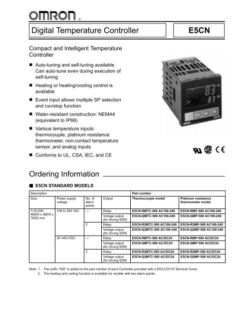
Digital Temperature Controller E5CN
Digital Temperature Controller E5CN
Digital Temperature Controller E5CN

Create successful ePaper yourself
Turn your PDF publications into a flip-book with our unique Google optimized e-Paper software.
<strong>Digital</strong> <strong>Temperature</strong> <strong>Controller</strong><br />
<strong>E5CN</strong><br />
Compact and Intelligent <strong>Temperature</strong><br />
<strong>Controller</strong><br />
Auto-tuning and self-tuning available.<br />
Can auto-tune even during execution of<br />
self-tuning<br />
Heating or heating/cooling control is<br />
available<br />
Event input allows multiple SP selection<br />
and run/stop function<br />
Water-resistant construction: NEMA4<br />
(equivalent to IP66)<br />
Various temperature inputs:<br />
thermocouple, platinum resistance<br />
thermometer, non-contact temperature<br />
sensor, and analog inputs<br />
Conforms to UL, CSA, IEC, and CE<br />
<br />
Ordering Information<br />
<strong>E5CN</strong> STANDARD MODELS<br />
Description<br />
Size<br />
1/16 DIN<br />
48(W) x 48(H) x<br />
78(D) mm<br />
Power supply<br />
voltage<br />
No. of<br />
alarm<br />
points<br />
Part number<br />
Output Thermocouple model Platinum resistance<br />
thermometer model<br />
100 to 240 VAC --- Relay <strong>E5CN</strong>-RMTC-500 AC100-240 <strong>E5CN</strong>-RMP-500 AC100-240<br />
Voltage output <strong>E5CN</strong>-QMTC-500 AC100-240 <strong>E5CN</strong>-QMP-500 AC100-240<br />
(for driving SSR)<br />
2 Relay <strong>E5CN</strong>-R2MTC-500 AC100-240 <strong>E5CN</strong>-R2MP-500 AC100-240<br />
Voltage output <strong>E5CN</strong>-Q2MTC-500 AC100-240 <strong>E5CN</strong>-Q2MP-500 AC100-240<br />
(for driving SSR)<br />
24 VAC/VDC --- Relay <strong>E5CN</strong>-RMTC-500 AC/DC24 <strong>E5CN</strong>-RMP-500 AC/DC24<br />
Voltage output <strong>E5CN</strong>-QMTC-500 AC/DC24 <strong>E5CN</strong>-QMP-500 AC/DC24<br />
(for driving SSR)<br />
2 Relay <strong>E5CN</strong>-R2MTC-500 AC/DC24 <strong>E5CN</strong>-R2MP-500 AC/DC24<br />
Voltage output <strong>E5CN</strong>-Q2MTC-500 AC/DC24 <strong>E5CN</strong>-Q2MP-500 AC/DC24<br />
(for driving SSR)<br />
Note: 1. The suffix “500” is added to the part number of each <strong>Controller</strong> provided with a E53-COV10 Terminal Cover.<br />
2. The heating and cooling function is available for models with two alarm points.
<strong>E5CN</strong><br />
<strong>E5CN</strong><br />
<strong>E5CN</strong> OPTION BOARDS<br />
The <strong>E5CN</strong> provides communications or event input functionality when mounted with one of the following Option Boards.<br />
Item Function Part number<br />
Communications Board RS-485 communication E53-CNH03<br />
Event Input Board Event input E53-CNHB<br />
Note:<br />
The heater burnout alarm is available by mounting the E53-CNH03 or E53-CNHB Option Unit on the <strong>E5CN</strong>.<br />
ACCESSORIES<br />
Terminal Cover (Sold Separately)<br />
Applicable <strong>Controller</strong><br />
<strong>E5CN</strong><br />
Part number<br />
E53-COV10<br />
Current Transformer (Sold Separately)<br />
Item Hole diameter Part number<br />
Current Transformer 5.8 dia. E54-CT1<br />
12.0 dia. E54-CT3
<strong>E5CN</strong><br />
<strong>E5CN</strong><br />
INPUT RANGES<br />
Platinum Resistance Thermometer Input<br />
Shaded ranges indicate default settings.<br />
Platinum resistance thermometer input<br />
Input type<br />
Platinum resistance thermometer<br />
<strong>Temperature</strong> range<br />
Name<br />
Pt100<br />
JPt100<br />
1800<br />
1700<br />
1600<br />
1500<br />
1400<br />
1300<br />
1200<br />
1100<br />
1000<br />
900<br />
850<br />
800<br />
700<br />
600<br />
500<br />
400<br />
300<br />
200<br />
500.0<br />
500.0<br />
100<br />
0<br />
--100<br />
--200<br />
100.0<br />
0.0<br />
100.0<br />
0.0<br />
--200 --199.9<br />
--199.9<br />
Set value 0 1 2 3 4<br />
Thermocouple Input<br />
Shaded ranges indicate default settings.<br />
<strong>Temperature</strong> range<br />
Input type<br />
1800<br />
1700<br />
1600<br />
1500<br />
1400<br />
1300<br />
1200<br />
1100<br />
1000<br />
900<br />
800<br />
700<br />
600<br />
500<br />
400<br />
300<br />
200<br />
100<br />
0<br />
--100<br />
--200<br />
Thermocouple<br />
Thermocouple input<br />
Name K J T E L U N R S B<br />
1300<br />
--200<br />
500.0<br />
--20.0<br />
850<br />
--100<br />
400.0<br />
--20.0<br />
400<br />
--200<br />
600<br />
0<br />
850<br />
--100<br />
400<br />
--200<br />
1300<br />
--200<br />
ES1A Non-contact<br />
<strong>Temperature</strong> Sensor<br />
K10 to K60 to K115 to K160 to<br />
70°C 120°C 165°C 260°C<br />
Analog input<br />
0to50mV<br />
Usable in the following<br />
ranges by scaling:<br />
--19999 to 9999 or<br />
--199.9 to 999.9<br />
Set value 0 1 2 3 4 5 6 7 8 9 10 11 12 13 14 15 16<br />
1700<br />
0<br />
1700<br />
0<br />
1800<br />
100<br />
70<br />
0<br />
120<br />
0<br />
165<br />
0<br />
260<br />
0<br />
Applicable standards by input type are as follows:<br />
K, J, T, E, N, R, S, B: JIS C1602-1995<br />
L: Fe-CuNi, DIN 43710-1985<br />
U: Cu-CuNi, DIN 43710-1985<br />
JPt100: JIS C1604-1989, JIS C1606-1989<br />
Pt100: JIS C1604-1997, IEC751<br />
Note:<br />
The ES1A Non-contact <strong>Temperature</strong> Sensor will be available soon.
<strong>E5CN</strong><br />
<strong>E5CN</strong><br />
Specifications<br />
RATINGS<br />
Supply voltage 100 to 240 VAC, 50/60 Hz 24 VAC, 50/60 Hz/24 VDC<br />
Operating voltage range<br />
85% to 110% of rated supply voltage<br />
Power consumption <strong>E5CN</strong> 7VA 4VA/3W<br />
Sensor input<br />
Thermocouple: K, J, T, E, L, U, N, R, S, B<br />
Platinum resistance thermometer: Pt100, JPt100<br />
Non-contact temperature sensor: K10 to 70C, K60 to 120C, K115 to 165C, K160 to 260C<br />
Voltage input: 0 to 50 mV<br />
Control output Relay output SPST-NO, 250 VAC, 3A (resistive load), electrical life: 100,000 operations<br />
Voltage output 12 VDC (PNP), max. load current: 21 mA, with short-circuit protection<br />
Alarm output<br />
SPST-NO, 250 VAC, 1 A (resistive load), electrical life: 100,000 operations<br />
Control method<br />
PID or ON/OFF control<br />
Setting method<br />
<strong>Digital</strong> setting using front panel keys<br />
Indication method<br />
7-segment digital display and single-lighting indicator<br />
Other functions<br />
According to <strong>Controller</strong> model<br />
Ambient temperature<br />
-10C to55C (14F to 131F) with no condensation or icing<br />
Ambient humidity<br />
Storage temperature<br />
25% to 85% relative humidity<br />
-25C to65C (-13F to 149F) with no condensation or icing
<strong>E5CN</strong><br />
<strong>E5CN</strong><br />
CHARACTERISTICS<br />
Indication accuracy<br />
Hysteresis<br />
Proportional band (P)<br />
Thermocouple:<br />
(0.5% of indicated value or 1C, whichever greater) 1 digit max. (See Note.)<br />
Platinum resistance thermometer:<br />
(0.5% of indicated value or 1C, whichever greater) 1 digit max.<br />
Analog input: 0.5% FS1 digit max.<br />
CT input: 5% FS1 digit max.<br />
0.1 to 999.9 EU (in units of 0.1 EU)<br />
0.1 to 999.9 EU (in units of 0.1 EU)<br />
Integral time (I) 0 to 3999 s (in units of 1 s)<br />
Derivative time (D) 0 to 3999 s (in units of 1 s)<br />
Control period<br />
1to99s(inunitsof1s)<br />
Manual reset value 0.0% to 100.0% (in units of 0.1%)<br />
Alarm setting range<br />
Sampling period<br />
Insulation resistance<br />
Dielectric strength<br />
Vibration resistance<br />
-1999 to 9999 (decimal point position depends on input type)<br />
500 ms<br />
20 MΩ min. (at 500 VDC)<br />
2000 VAC, 50 or 60 Hz for 1min (between different charging terminals)<br />
10 to 55 Hz, 10 m/s 2 for 2 hours each in X, Y and Z directions<br />
Shock resistance 300 m/s 2 , 3 times each in 3 axes, 6 directions (relay: 100 m/s 2 )<br />
Weight Approx. 150 g Mounting bracket: Approx. 10g<br />
Protective structure Front panel NEMA4 for indoor use (equivalent to IP66)<br />
Rear case<br />
Terminals<br />
IP20<br />
IP00<br />
Memory protection EEPROM (non-volatile memory) (number of writes: 100,000)<br />
EMC Emission Enclosure: EN55011 Group 1 class A<br />
Emission AC Mains:<br />
EN55011 Group 1 class A<br />
Immunity ESD: EN61000-4-2: 4 kV contact discharge (level 2)<br />
8 kV air discharge (level 3)<br />
Immunity RF-interference: ENV50140: 10 V/m (amplitude modulated,<br />
80MHzto1GHz)(level3)<br />
10 V/m (pulse modulated, 900 MHz)<br />
Immunity Conducted Disturbance: ENV50141: 10 V (0.15 to 80 MHz) (level 3)<br />
Immunity Burst: EN61000-4-4: 2 kV power-line (level 3)<br />
2 kV I/O signal-line (level 4)<br />
Approval standards<br />
UL3121-1, CSA22.2 No. 14, E.B.1402C<br />
Conforms to EN50081-2, EN50082-2, EN61010-1 (IEC1010-1)<br />
Conforms to VDE0106/part 100 (Finger Protection), when the terminal cover is mounted.<br />
Note:<br />
The indication of K thermocouples in the -200 to 1300°C range, and T and N thermocouples at a temperature of -100°C or less,<br />
and U and L thermocouples at any temperature is ±2°C±1 digit maximum. The indication of B thermocouples at a temperature of<br />
400°C or less is unrestricted.<br />
The indication of R and S thermocouples at a temperature of 200°C orlessis±3°C±1 digit maximum.
<strong>E5CN</strong><br />
<strong>E5CN</strong><br />
COMMUNICATIONS SPECIFICATIONS<br />
Transmission path connection<br />
Communications method<br />
Synchronization method<br />
Baud rate<br />
Transmission code<br />
Data bit length<br />
Stop bit length<br />
Error detection<br />
Flow control<br />
Interface<br />
Retry function<br />
Communications buffer<br />
Multiple points<br />
RS-485 (two-wire, half duplex)<br />
Start-stop synchronization<br />
1,200/2,400/4,800/9,600/19,200 bps<br />
ASCII<br />
7or8bits<br />
1or2bits<br />
Vertical parity (none, even, odd)<br />
Frame check sequence (FCS): with SYSMAC WAY<br />
Block check character (BCC): with CompoWay/F<br />
Not available<br />
RS-485<br />
Not available<br />
40 bytes<br />
Note:<br />
The baud rate, data bit length, stop bit length, or vertical parity can be individually set using the communications setting level.<br />
CURRENT TRANSFORMER (SOLD SEPARATELY) RATINGS<br />
Dielectric strength<br />
1,000 VAC (1 min)<br />
Vibration resistance 50 Hz 98 m/s 2<br />
Weight E54-CT1 Approx. 11.5 g<br />
E54-CT3<br />
Accessories (E54-CT3 only) Armature 2<br />
Plug 2<br />
Approx. 50 g<br />
HEATER BURNOUT ALARM SPECIFICATIONS<br />
Max. heater current Single-phase AC: 50 A (See Note 1.)<br />
Input current readout accuracy<br />
±5%FS±1 digit max.<br />
Heater burnout alarm setting range 0.0 to 50.0 A (0.1 A units) (See Note 2.)<br />
Min. detection ON time 190 ms (See Note 3.)<br />
Note: 1. When heater burnout is detected on a 3-phase heater, use the K2CU-FA-GS (with gate input terminal).<br />
2. When the set value is “00 A,” the heater burnout alarm will always be OFF. When the set value is “50.0 A,” the heater burnout<br />
alarm will always be ON.<br />
3. When the control output ON time is less than 190 ms, heater burnout detection and heater current measurement will not be<br />
carried out.
<strong>E5CN</strong><br />
<strong>E5CN</strong><br />
Nomenclature<br />
<strong>E5CN</strong><br />
Operation Indicators<br />
1. AL1 (alarm 1)<br />
Lights when alarm 1 output<br />
is ON.<br />
AL2 (alarm 2)<br />
Lights when alarm 2 output<br />
is ON.<br />
2. HB (heater burnout alarm<br />
display)<br />
Lights when a heater<br />
burnout is detected.<br />
The heater burnout alarm<br />
remains ON by setting the<br />
heater burnout latch. To<br />
reset, turn the power supply<br />
OFF and then ON or<br />
set the heater burnout<br />
alarm value to “0.0A.”<br />
3. OT1, OT2 (control output<br />
1, control output 2)<br />
Lights when control output<br />
1 and/or control output 2<br />
(cool) are ON.<br />
4. STP (stop)<br />
Lights when control of the<br />
<strong>E5CN</strong> has been stopped.<br />
During control, this indicator<br />
lights when an event or<br />
the run/stop function has<br />
stopped, or this indicator<br />
is out.<br />
5. CMW (communications<br />
writing control)<br />
Lights when communications<br />
writing is enabled<br />
and is out when it is<br />
disabled.<br />
<strong>Temperature</strong> Unit<br />
The temperature unit is displayed<br />
when the display unit parameter<br />
is set to a temperature. Indication<br />
is determined by the currently<br />
selected “temperature unit”<br />
parameter set value. When this<br />
parameter is set to “°C,” “” is<br />
displayed, and when set to “°F,”<br />
“” is displayed.<br />
No. 1 Display<br />
Displays the process value or<br />
parameter type.<br />
No. 2 Display<br />
Displays the set point, manipulated<br />
variable, or set value (setup)<br />
of the parameter.<br />
Up Key<br />
Each press of this key increases<br />
values displayed on the No.2<br />
display. Holding down this key<br />
continuously increases values.<br />
Down Key<br />
Each press of this key decreases<br />
values displayed on the No.2<br />
display. Holding down this key<br />
continuously decreases values.<br />
Level + Mode Keys<br />
This key combination sets the<br />
<strong>E5CN</strong> to the “protect level.”<br />
Level Key<br />
Press this key to select the setup level. The<br />
setup level is selected in this order: “operation<br />
level” ←→ “adjustment level,” “initial setting<br />
level” ←→ “communications setting level.”<br />
Mode Key<br />
Press this key to select parameters<br />
within each level.
<strong>E5CN</strong><br />
<strong>E5CN</strong><br />
Operation<br />
INITIAL SETUP<br />
On previous <strong>Controller</strong>s, sensor input type, alarm type and<br />
control period were set on DIP switches. These hardware<br />
settings are now set in parameters in setup menus. The and<br />
keys are used to switch between setup menus, and the<br />
amount of time that you hold the keys down determines which<br />
setup menu you move to. This section describes two typical<br />
examples.<br />
Note: On the E5GN, the Keyisthe Key.<br />
1. ON/OFF Control<br />
Typical Application Examples<br />
Typical Example<br />
Input type: 0 K thermocouple -200 to 1300°C<br />
Control method: ON/OFF control<br />
Alarm type: 2 upper limit<br />
Alarm value 1: 20°C (For setting deviation)<br />
Set point: 100°C<br />
Change only the alarm value 1 and set point.<br />
The rest must be left as default settings.<br />
• Changing Parameters<br />
Setup procedure<br />
Power ON<br />
Operation level<br />
Power ON<br />
Process value/<br />
set point<br />
Initial setting level<br />
Press key for at least<br />
three seconds.<br />
Control stops.<br />
indicates that there is a parameter.<br />
Keep on pressing the mode key until<br />
the desired parameter is selected.<br />
Set input<br />
specifications<br />
Set control<br />
specifications<br />
Check input<br />
type.<br />
Check that control<br />
is ON/OFF<br />
control.<br />
Input type<br />
In ON/OFF<br />
control <br />
• Changing Set Values<br />
Set alarm type<br />
Check alarm<br />
type.<br />
Alarm 1<br />
type <br />
Use the or keys to<br />
change the set value displayed<br />
in the setup menu.<br />
Display<br />
<strong>E5CN</strong><br />
No. 1 display<br />
E5GN<br />
No. 1 display<br />
Press key for at<br />
least one second.<br />
Operation level<br />
No. 2 display<br />
No. 2 display<br />
Set the set point<br />
Press keys<br />
to set set point to<br />
“100C.”<br />
Process value/<br />
set point <br />
Check operation<br />
state<br />
Set alarm values<br />
Make sure that<br />
control is running.<br />
Press keys<br />
to set alarm value<br />
to “20C.”<br />
During run<br />
<br />
During stop<br />
Alarm<br />
value 1<br />
Start operation<br />
Start operation
<strong>E5CN</strong><br />
<strong>E5CN</strong><br />
2. PID Control Using Auto-tuning<br />
Typical Application Example<br />
• Changing Parameters<br />
Typical Example<br />
Input type: 4 T thermocouple -200 to 400°C<br />
Control method: PID control<br />
ST (self-tuning): OFF<br />
Calculate PID constants by AT (auto-tuning).<br />
Alarm type: 2 upper limit<br />
Alarm value 1: 30°C (For setting deviation)<br />
Set point: 150°C<br />
indicates that there is a parameter. Keep<br />
on pressing the mode key until the desired<br />
parameter is selected.<br />
Setup procedure<br />
Power ON<br />
Power ON<br />
Operation level<br />
• Changing Set Values<br />
Use the or keys to<br />
change the set value displayed<br />
in the setup menu.<br />
Process value/<br />
set point<br />
Press key for at least three<br />
seconds. Control stops.<br />
Display<br />
<strong>E5CN</strong><br />
No. 1 display<br />
E5GN<br />
No. 1 display<br />
Set input<br />
specifications<br />
Initial setting level<br />
Press<br />
keys to select<br />
input type.<br />
Input type <br />
Set control<br />
specifications<br />
Press<br />
keys to select<br />
PID control.<br />
In PID control<br />
No. 2 display<br />
No. 2 display<br />
Self-tuning<br />
Press<br />
keys to set ST<br />
to OFF.<br />
To cancel ST<br />
Check control period<br />
Check alarm type<br />
Check the<br />
control period.<br />
Check alarm<br />
type.<br />
Control period<br />
(heat) (unit:<br />
seconds)<br />
Alarm 1 type <br />
(upper-limit<br />
alarm)<br />
When set to ON,<br />
self-tuning operates.<br />
Recommended settings:<br />
20 seconds for<br />
the relay output and<br />
2 seconds for the<br />
SSR output.<br />
PV/SP<br />
After AT execution.<br />
Operation level<br />
Press<br />
key for at least one second.<br />
During AT execution.<br />
Set the set point<br />
Press keys<br />
to set set point to<br />
“150C.”<br />
Process value/<br />
set point <br />
While AT is being<br />
executed, SP will flash.<br />
After AT execution.<br />
AT execution<br />
Adjustment level<br />
Execute AT<br />
(auto-tuning).<br />
Press<br />
key for less than one second.<br />
To execute AT<br />
Set to for executing<br />
AT and to <br />
for stopping AT.<br />
During AT execution.<br />
Operation level<br />
Make sure that<br />
set point is<br />
“150C.”<br />
Press<br />
key for less than one second.<br />
Process value/<br />
set point <br />
Set operation status<br />
Make sure that<br />
control is running.<br />
During run<br />
Set alarm values<br />
Press<br />
keys to set<br />
alarm value to<br />
“30C.”<br />
Alarm<br />
value 1<br />
<br />
Start operation<br />
Start program execution
<strong>E5CN</strong><br />
<strong>E5CN</strong><br />
Specification Setting After Turning ON Power<br />
OUTLINE OF OPERATION PROCEDURES<br />
Key Operation<br />
In the following descriptions, all the parameters are introduced in the display sequence. Some parameters may not be displayed<br />
depending on the protect settings and operation conditions.<br />
Power ON<br />
key<br />
1 second min.<br />
Operation level<br />
key<br />
Less than<br />
1 second<br />
key<br />
3 second min.<br />
Adjustment level<br />
Control stops<br />
+ key<br />
1 second min.<br />
key<br />
1 second min.<br />
Initial setting level<br />
Advanced<br />
function setting level<br />
Calibration level<br />
key<br />
Less than<br />
1 second<br />
Password input<br />
set value “--169”<br />
Password input<br />
set value “1201”<br />
Communications<br />
setting level<br />
Control in progress<br />
Control stopped<br />
Level change<br />
Protect level<br />
Note: 1. Of these levels, the initial setting level,<br />
communications setting level, advanced function<br />
setting level and calibration level can be used only<br />
when control has stopped. Note that control is<br />
stopped when these four levels are selected. When<br />
switched back to the operation level from one of these<br />
levels, control will start.<br />
2. For the calibration mode, refer to the relevant<br />
Operation Manual (H100 or H101).<br />
3. On the E5GN, the Key is the Key.<br />
DESCRIPTION OF EACH LEVEL<br />
Operation Level<br />
This level is displayed when you turn the power ON. You can<br />
move to the protect level, initial setting level and adjustment level<br />
from this level.<br />
Normally, select this level during operation. During operation, the<br />
process value, set point and manipulated variable can be<br />
monitored, and the alarm value and upper- and lower-limit alarms<br />
can be monitored and modified.<br />
Adjustment Level<br />
To select this level, press the key once for less than one<br />
second.<br />
This level is for entering set values and offset values for control.<br />
This level contains parameters for setting the set values, AT<br />
(auto-tuning), communications writing enable/disable, hysteresis,<br />
multi-SP, input shift values, heater burnout alarm (HBA) and PID<br />
constants. You can move to the top parameter of the operation<br />
level or initial setting level from here.<br />
Initial Setting Level<br />
To select this level, press the key for at least three seconds in<br />
the operation level. This level is for specifying the input type,<br />
selecting the control method, control period, setting direct/reverse<br />
action and alarm type. You can move to the advanced function<br />
setting level or communications setting level from this initial<br />
setting level. To return to the operation level, press the key for<br />
at least one second. To move to the communications setting<br />
level, press the key once for less than one second.<br />
Protect Level<br />
To select this level, simultaneously press the and keys<br />
for at least one second. This level is to prevent unwanted or<br />
accidental modification of parameters. Protected levels will not be<br />
displayed, and so the parameters in that level cannot be<br />
modified.
<strong>E5CN</strong><br />
<strong>E5CN</strong><br />
Communications Setting Level<br />
To select this level, press the key once for less than one<br />
second in the initial setting level. When the communications<br />
function is used, set the communications conditions in this level.<br />
Communicating with a personal computer (host computer) allows<br />
set points to be read and written, and manipulated variables to be<br />
monitored.<br />
Advanced Function Setting Level<br />
To select this level, you must enter the password (“-169”) in the<br />
initial setting level.<br />
You can move only to the calibration level from this level.<br />
This level is for setting the automatic return of display mode, MV<br />
limiter, event input assignment, standby sequence, alarm<br />
hysteresis, ST (self-tune) and to move to the user calibration<br />
level.<br />
Calibration Level<br />
To select this level, you must enter the password (“1201”) in the<br />
advanced function setting level. This level is for offsetting<br />
deviation in the input circuit.<br />
You cannot move to other levels by operating the keys on the<br />
front panel from the calibration level. To cancel this level, turn the<br />
power OFF then back ON again.
<strong>E5CN</strong><br />
<strong>E5CN</strong><br />
SPECIFICATION SETTING (AFTER<br />
TURNING ON POWER)<br />
Initial Setting Level<br />
This level is used for setting basic specifications of the<br />
<strong>Temperature</strong> <strong>Controller</strong>. Using this level, set the input type for<br />
selecting the input to be connected such as the thermocouple or<br />
platinum resistance thermometer and set the range of set point<br />
and the alarm mode.<br />
Initial setting level<br />
Input type<br />
Power ON<br />
Scaling upper limit<br />
key<br />
1 second min.<br />
key<br />
1 second min.<br />
Operation level<br />
Adjustment level<br />
key<br />
Less than 1 second<br />
Initial setting<br />
level<br />
Advanced function<br />
setting level<br />
key<br />
3 second min.<br />
key<br />
Less than 1 second<br />
Password input<br />
set value “-169”<br />
Control stops.<br />
Communications<br />
setting level<br />
+ key<br />
1 second min.<br />
Protect level<br />
Scaling lower limit<br />
Decimal point<br />
<strong>Temperature</strong> unit<br />
Set point upper limit<br />
Set point lower limit<br />
Calibration level<br />
Password input<br />
set value “1201”<br />
The move from the operation level to the initial setting level,<br />
press key for three seconds or more.<br />
The initial setting level is not displayed when<br />
“initial/communications protection” is set to “2.” This initial setting<br />
level can be used when “initial setting/communications<br />
protection” is set to “0” or “1.”<br />
The “scaling upper limit,” “scaling lower limit,” and “decimal point”<br />
parameters are displayed when an analog voltage input is<br />
selected as the input type.<br />
PID / ON/OFF<br />
Standard/heating and<br />
cooling<br />
: Standard<br />
: Heating/cooling<br />
ST<br />
Control period (heat)<br />
Control period (cool)<br />
: ON/OFF control<br />
: PID control<br />
: Enabled<br />
: Disabled<br />
Direct/reverse operation<br />
: Reverse<br />
operation<br />
: Direct<br />
operation<br />
Alarm 1 type<br />
Alarm 2 type<br />
Move to advanced<br />
function setting level<br />
To return to the operation level, press the<br />
one second<br />
* Not displayed as default setting.<br />
key for longer than<br />
Note: 1. Displayed only with models provided with an alarm<br />
function.<br />
2. Displayed only with the <strong>E5CN</strong> provided with a twopoint<br />
alarm function.
<strong>E5CN</strong><br />
<strong>E5CN</strong><br />
INPUT TYPE<br />
Using a Thermocouple Input Type<br />
When using a thermocouple input type, follow the specifications listed in the following table.<br />
Input type Specifications Set Value Input <strong>Temperature</strong> Range<br />
Thermocouple K 0 --200 to 1300 (°C) /--300 to 2300 (°F)<br />
1 --20.0 to 500.0 (°C) /0.0 to 900.0 (°F)<br />
J 2 --100 to 850 (°C) /--100 to 1500 (°F)<br />
3 --20.0 to 400.0 (°C) /0.0 to 750.0 (°F)<br />
T 4 --200 to 400 (°C) /--300 to 700 (°F)<br />
E 5 0to600(°C) /0 to 1100 (°F)<br />
L 6 --100 to 850 (°C) /--100 to 1500 (°F)<br />
U 7 --200 to 400 (°C) /--300 to 700 (°F)<br />
N 8 --200 to 1300 (°C) /--300 to 2300 (°F)<br />
R 9 0 to 1700 (°C) /0 to 3000 (°F)<br />
S 10 0 to 1700 (°C) /0 to 3000 (°F)<br />
B 11 100 to 1800 (°C) /300 to 3200 (°F)<br />
Non-contact temperature sensor ES1A K10to70C 12 0to90(°C) /0 to 190 (°F)<br />
K60to120C 13 0to120(°C) /0 to 240 (°F)<br />
K115 to 165C 14 0to165(°C) /0 to 320 (°F)<br />
K160 to 260C 15 0to260(°C) /0 to 500 (°F)<br />
Analog input 0to50mV 16 One of following ranges depending on the<br />
results of scaling: 1999 to 9999, 199.9 to<br />
999.9<br />
Note:<br />
The initial settings are: 0: --200 to 1300C/--300 to 2300F.<br />
Using a Platinum Resistance Thermometer Input Type<br />
When using the platinum resistance thermometer input type, follow the specifications listed in the following table.<br />
Input type Specifications Set Value Input <strong>Temperature</strong> Range<br />
Platinum resistance thermometer Pt100 0 --200 to 850 (°C) /--300 to 1500 (°F)<br />
1 --199.9 to 500.0 (°C)/--199.9 to 900.0 (°F)<br />
2 0.0 to 100.0 (°C) /0.0 to 210.0 (°F)<br />
JPt100 3 --199.9 to 500.0 (°C)/--199.9 to 900.0 (°F)<br />
4 0.0 to 100.0 (°C) /0.0 to 210.0 (°F)<br />
Note: 1. The initial settings are: 0: Pt100 --200 to 850C/--300 to 1500F.<br />
2. The ES1A Non-contact <strong>Temperature</strong> Sensor will be available soon.
<strong>E5CN</strong><br />
<strong>E5CN</strong><br />
ALARM 1 AND ALARM 2<br />
For the alarm 1 and alarm 2, select alarm types out of the 12 alarm types listed in the following table.<br />
Set Value Alarm Type Alarm Output Operation<br />
When X is positive<br />
0 Alarm function OFF Output OFF<br />
1 *1 Upper- and lower-limit (deviation)<br />
When X is negative<br />
*2<br />
2 Upper-limit (deviation)<br />
3 Lower-limit (deviation)<br />
4 *1 Upper- and lower-limit range<br />
(deviation) *3<br />
5 *1 Upper- and lower-limit with standby<br />
sequence (deviation) *4<br />
6 Upper-limit with standby sequence<br />
(deviation)<br />
7 Lower-limit with standby sequence<br />
(deviation)<br />
8 Absolute-value upper-limit<br />
9 Absolute-value lower-limit<br />
10 Absolute-value upper-limit with<br />
standby sequence<br />
11 Absolute-value lower-limit with<br />
standby sequence<br />
*1: With set values 1, 4 and 5, the upper and lower limit values<br />
can be set independently for each alarm type and are expressed<br />
as “L” and “H.”<br />
Following operations are for cases when an alarm set point is “X”<br />
or negative.<br />
*2: Set value: 1, upper- and lower-limit alarm<br />
*4: Set value: 5, upper- and lower-limit with standby sequence<br />
Case 1 Case 2<br />
Same as for the upper- and lower-limit<br />
alarm. However, when the upper limit<br />
and lower limit hysteresis overlaps:<br />
Always OFF<br />
Example<br />
Case 1 Case 2 Case 3 (Always ON)<br />
*3: Set value: 4, upper- and lower-limit range<br />
Example: When the alarm is set ON at 110C/F or higher.<br />
• When an alarm type<br />
other than the absolutevalue<br />
alarm is selected<br />
• When the absolutevalue<br />
alarm is selected<br />
(For alarm types 1 to 7)<br />
The alarm value is set as a<br />
deviation from the set point.<br />
(For alarm types 8 to 11)<br />
The alarm value is set as an<br />
absolute value from the alarm<br />
value of 0C/F.<br />
Case 1 Case 2 Case 3 (Always OFF)<br />
Alarm value<br />
Alarm value<br />
Set point<br />
100°C/°F<br />
0°C/°F
<strong>E5CN</strong><br />
<strong>E5CN</strong><br />
PARAMETERS<br />
Parameters related to setting items for each level are marked in<br />
boxes in the flowcharts and brief descriptions are given as<br />
required. At the end of each setting item, press the mode key to<br />
return to the beginning of each level.<br />
Operation Level<br />
Power ON<br />
Display<br />
<strong>E5CN</strong><br />
No. 1 display<br />
E5GN<br />
No. 1 display<br />
PV<br />
Add in the “additional<br />
PV display” parameter.<br />
PV/SP<br />
No. 2 display<br />
No. 2 display<br />
Multi-SP<br />
Select SP.<br />
Power ON<br />
Set point during SP ramp<br />
key<br />
1 second<br />
min.<br />
Operation level<br />
Adjustment level<br />
key<br />
Less than 1 second<br />
key 3 second min.<br />
Control stops.<br />
+ key<br />
1 second min.<br />
Heater current value monitor<br />
Run/stop<br />
Current value<br />
monitor of HBA<br />
: RUN<br />
: STOP<br />
Initial setting level<br />
Communications<br />
setting level<br />
key<br />
Less than 1 second<br />
key<br />
1 second<br />
min.<br />
Advanced function<br />
setting level<br />
Calibration level<br />
Password input<br />
set value “-169”<br />
Password input<br />
set value “1201”<br />
Control in progress<br />
Control stopped<br />
Level change<br />
Protect level<br />
Alarm value 1<br />
Upper-limit<br />
alarm value 1<br />
Lower-limit<br />
alarm value 1<br />
Alarm value 2<br />
Upper-limit<br />
alarm value 2<br />
Set either of<br />
these parameters.<br />
Set either of<br />
these parameters.<br />
Lower-limit<br />
alarm value 2<br />
MV monitor (heat)<br />
MV monitor (cool)
<strong>E5CN</strong><br />
<strong>E5CN</strong><br />
Initial Setting Level<br />
Adjustment Level<br />
Input type<br />
AT execute/cancel<br />
Auto-tuning<br />
Scaling upper limit<br />
Scaling lower limit<br />
Decimal point<br />
Number of displayed digits<br />
For analog input<br />
(Input type: 16)<br />
0- to 50-mV setting<br />
Communications writing<br />
Heater current<br />
value monitor<br />
Heater burnout<br />
detection<br />
: Enabled<br />
: Disabled<br />
HBA<br />
function<br />
<strong>Temperature</strong> unit<br />
Set point upper limit<br />
: °C<br />
: °F<br />
Set point 0<br />
Set point 1<br />
Set point lower limit<br />
Limit the set point.<br />
Set point 2<br />
Set points used<br />
by multi-SP<br />
PID / ON/OFF<br />
Select the control system.<br />
: ON/OFF control<br />
: PID control<br />
Set point 3<br />
Standard/heating and cooling<br />
: Standard<br />
: Heating/cooling<br />
<strong>Temperature</strong> input shift<br />
1-point shift<br />
ST<br />
Self-tuning<br />
: Enabled<br />
: Disabled<br />
Upper-limit temperature<br />
input shift value<br />
2-point shift<br />
Control period (heat)<br />
Control period (cool)<br />
Set the pulse<br />
output cycle.<br />
Lower-limit temperature<br />
input shift value<br />
Proportional band<br />
P<br />
Direct/reverse operation<br />
: Reverse<br />
: Direct<br />
Integral time<br />
I<br />
PID settings<br />
Alarm 1 type<br />
Derivative time<br />
D<br />
Alarm 2 type<br />
Move to advanced function<br />
setting level<br />
Select the alarm<br />
mode.<br />
Cooling coefficient<br />
Dead band<br />
Used in heating and<br />
cooling control<br />
Manual reset value<br />
Clear the offset during<br />
stabilization of P or PD<br />
control.<br />
Hysteresis (heat)<br />
Hysteresis (cool)<br />
Set hysteresis.
<strong>E5CN</strong><br />
<strong>E5CN</strong><br />
Advanced Function Setting Level<br />
Protect Level<br />
Parameter initialize<br />
Number of multi-SP uses<br />
Event input assignment 1<br />
Event input assignment 2<br />
Multi-SP uses<br />
SP ramp set value<br />
Standby sequence reset<br />
method<br />
Alarm 1 open in alarm<br />
Alarm 1 hysteresis<br />
Alarm 2 open in alarm<br />
Alarm 2 hysteresis<br />
HBA ON/OFF<br />
Heater burnout latch<br />
Heater burnout hysteresis<br />
ST stable range<br />
For setting deviation.<br />
α<br />
PID parameter<br />
MV upper limit<br />
MV lower limit<br />
Resets to the default value.<br />
Input setting: Multiple<br />
SP/RUN/STOP<br />
ON/OFF setting of alarm<br />
output 1<br />
ON/OFF setting of alarm<br />
output 2<br />
Limitations to MV<br />
Operation/adjustment protection<br />
Restricts display and modification of menus in the<br />
operation and adjustment levels.<br />
Initial setting/communications protection<br />
Restricts display and modification of menus in the initial<br />
setting, operation level and adjustment levels.<br />
Setting change protection<br />
Protects changes to setups by operating the front<br />
panel keys.<br />
Operation/Adjustment Protection<br />
The following table shows the relationship between set values<br />
and the range of protection.<br />
Level<br />
Set value<br />
0 1 2 3<br />
Operation PV <br />
levell<br />
PV/SP<br />
Other X X<br />
Adjustment level X X X<br />
When this parameter is set to “0,” parameters are not protected.<br />
Default setting: 0<br />
: Can be displayed and changed<br />
: Can be displayed<br />
: Cannot be displayed and move to other levels not possible<br />
Initial Setting/Communications Protection<br />
This protect level restricts movement to the initial setting level,<br />
communications setting level and advanced function setting level.<br />
Set<br />
value<br />
Initial setting<br />
level<br />
Communications<br />
setting level<br />
0 <br />
1 X<br />
2 X X X<br />
Default setting: 1<br />
: Move to other levels possible<br />
: Move to other levels not possible<br />
Advanced<br />
function<br />
setting level<br />
Setting Change Protection<br />
This protect level protects setup from being changed by<br />
operating the keys on the front panel.<br />
Input digital filter<br />
For setting time constant in seconds.<br />
Additional PV display<br />
Displayed first in the operation level<br />
Set value<br />
OFF<br />
ON<br />
Description<br />
Setup can be changed by key operation.<br />
Setup cannot be changed by key operation.<br />
(The protect level, can be changed.)<br />
Manipulated variable display<br />
Default setting: OFF<br />
Automatic return of display mode<br />
Automatically reset to the operation level<br />
when no key operation are performed.<br />
Move to calibration level
<strong>E5CN</strong><br />
<strong>E5CN</strong><br />
Communications Setting Level<br />
Set the <strong>E5CN</strong>/E5GN communications specifications in the communications setting level. For setting communications parameters, use the<br />
<strong>E5CN</strong>/E5GN panel. The communications parameters and their settings are listed in the following table.<br />
Parameter Displayed characters Set (monitor) value Set value<br />
Communications unit No. 0to99 0.1to99<br />
Baud rate 1.2/2.4/4.8/9.6/19.2 (kbps) 1.2/2.4/4.8/9.6/19.2<br />
Data bits 7/8 (bit) 7/8 (bit)<br />
Stop bits 1/2 1/2 (bit)<br />
Parity None, even, odd //<br />
Note:<br />
The highlighted values indicate default settings.<br />
Before executing communications with the <strong>E5CN</strong>/E5GN, set the<br />
communications unit No., baud rate, etc., through key operations<br />
as described below. As for other operations, refer to the relevant<br />
Operation Manual.<br />
1. Press the key for at least three seconds in the “operation<br />
level.” The level moves to the “initial setting level.”<br />
2. Press the key for less than one second. The “initial<br />
setting level” moves to the “communications setting level.”<br />
3. Pressing the key advances the parameters as shown<br />
in the following figure.<br />
4. Press the or keys to change the parameter setups.<br />
Communications<br />
unit No.<br />
Baud rate<br />
Data bits<br />
Stop bits<br />
Parity<br />
Communications Unit No. ()<br />
When communicating with the host computer, the unit number<br />
must be set in each <strong>Temperature</strong> <strong>Controller</strong> so that the host<br />
computer can identify each <strong>Temperature</strong> <strong>Controller</strong>. The number<br />
can be set in a range from 0 to 99 in increments of 1. The default<br />
setting is 1. When using more than one Unit, be careful not to<br />
use the same number twice. Duplicate settings will cause<br />
malfunction. This value becomes valid when the power is turned<br />
OFF and ON again.<br />
Baud Rate ()<br />
Use this parameter to set the speed of communications with the<br />
host computer. It can be set to one of the following values; 1.2<br />
(1200 bps), 2.4 (2400 bps), 4.8 (4800 bps), 9.6 (9600 bps), and<br />
19.2 (19200 bps).<br />
This setting becomes valid when the power is turned OFF and<br />
ON again.<br />
Data Bits ( )<br />
Use this parameter to change the communications data bit length<br />
to7bitsor8bits.<br />
Stop Bits ()<br />
Use this parameter to change the communications stop bit to 1 or<br />
2.<br />
Parity ()<br />
Use this parameter to set the communications parity to None,<br />
Even, or Odd.<br />
Note: On the E5GN, the Keyisthe Key.<br />
Set each communications parameter to match those of the<br />
communicating personal computer.
<strong>E5CN</strong><br />
<strong>E5CN</strong><br />
TROUBLESHOOTING<br />
When an error occurs, an error code will be displayed on the No. 1 display. Check the contents of an error and take appropriate<br />
countermeasures.<br />
No. 1 display Type of error Countermeasures<br />
Input error Check the wiring of inputs for miswiring, disconnections, short-circuits, and the input<br />
type.<br />
Memory error First, turn the power OFF then back ON again. If the display remains the same, the<br />
Unit must be repaired. If the display is restored, then a probable cause can be external<br />
noise affecting the control system. Check for external noise.<br />
Display range over Though not error, this is displayed when the process value exceeds the display range<br />
when the control range is larger than the display range.<br />
• When less than “-1999”<br />
• When larger than “9999”<br />
HB error First, turn the power OFF then back ON again. If the display remains the same, the<br />
controller must be repaired. If the display is restored, then a probable cause can be<br />
electrical noise affecting the control system. Check for electrical noise.<br />
Note:<br />
Error will be displayed only when the display is set for the PV or PV/SP.<br />
Fuzzy Self-tuning<br />
The fuzzy self-tuning (ST) is a function that automatically calculates an optimum PID constant depending on items to be controlled.<br />
FEATURE<br />
The <strong>Temperature</strong> <strong>Controller</strong> determines when to execute this fuzzy self-tuning.<br />
FUNCTIONS<br />
SRT: Performs PID tuning according to the step response method when the SP is changed.<br />
LCT: Performs PID tuning according to the limit cycle method when the SP is changed.<br />
Requirements for SRT Functionality<br />
The ST will be executed according to the step response method when the following conditions are satisfied when operation is started or<br />
when the SP is changed.<br />
When operation is started<br />
1. The SP at the startup is different from the SP at the time the<br />
previous SRT was executed. (See Note.)<br />
2. The temperature upon startup is smaller than the SP in the<br />
reverse operation and larger than the SP in the direct<br />
operation.<br />
3. Restarting of operation is not due to an input error.<br />
Note: The “SP that existed when the previous SRT was<br />
executed” refers to the SP used for obtaining the PID<br />
constant in the previous SRT.<br />
When SP is changed<br />
1. The SP after change is different from the SP at the time the<br />
previous SRT was executed. (See Note.)<br />
2. In the reverse operation, the value obtained by deducting the<br />
SP before change from the SP after change is larger than the<br />
ST stable range. In the direct operation, the value obtained by<br />
deducting the SP after change from the SP before change is<br />
larger than the ST stable range.<br />
3. The SP change width is larger than the current proportional<br />
band x 1.27 + 4.<br />
4. The temperature is in the stable state. (It can be in the<br />
balanced state if no output is generated when the power is<br />
turned ON.)<br />
If the SP is changed while SRT is being executed and if SRT completion conditions are satisfied, no PID change will take place.<br />
Stabilization State<br />
Measured values remain in the stable range for a certain period<br />
of time.<br />
<strong>Temperature</strong><br />
This inclination is referred to as<br />
R.<br />
ST stable range<br />
Balanced State<br />
Output is 0% for 60 seconds and measured values fluctuate<br />
within the width of the stable range.<br />
SRT completion<br />
Time
<strong>E5CN</strong><br />
<strong>E5CN</strong><br />
Dimensions<br />
Unit: mm (inch)<br />
<strong>E5CN</strong><br />
Panel Cutouts<br />
48 x 48<br />
9<br />
102<br />
(4.02)<br />
93<br />
78<br />
Mounted Separately<br />
60 min.<br />
Group Mounted<br />
(48number of units -2.5)<br />
+1.0<br />
0<br />
45 +0.6<br />
0<br />
58<br />
44.8<br />
48.8<br />
(1.92)<br />
60 min.<br />
45<br />
+0.6<br />
0<br />
Group mounting does<br />
not allow waterproofing.<br />
45<br />
+0.6<br />
0<br />
Note:<br />
The suffix “500” is added to the model number of each<br />
<strong>Controller</strong> provided with a E53-COV10 Terminal Cover.<br />
• Recommended panel thickness is 1 to 5 mm.<br />
• Group mounting is not possible in the vertical direction.<br />
(Maintain the specified mounting space between <strong>Controller</strong>s<br />
when they are group mounted.) To mount the <strong>E5CN</strong> so that<br />
it is waterproof, apply the waterproof seal to the <strong>E5CN</strong>.<br />
• When two or more <strong>E5CN</strong>s are mounted, make sure that the<br />
surrounding temperature does not exceed the allowable<br />
operating temperature, as specified in the specifications.<br />
TERMINAL COVER<br />
E53-COV10<br />
48<br />
(1.89)<br />
48.8<br />
(1.92)<br />
22<br />
(0.87)<br />
9.1<br />
(0.36)
<strong>E5CN</strong><br />
<strong>E5CN</strong><br />
CURRENT TRANSFORMER (SOLD SEPARATELY)<br />
E54-CT1<br />
21<br />
(0.83)<br />
15<br />
25<br />
(0.98) 3<br />
5.8 dia.<br />
10.5<br />
2.8<br />
7.5<br />
40<br />
(1.57)<br />
Two, 3.5 dia.<br />
10<br />
30<br />
(1.18)<br />
E54-CT3<br />
30<br />
(1.18)<br />
12 dia.<br />
2.36 dia.<br />
9<br />
40 x 40<br />
Two, M3 (depth: 4)<br />
15<br />
(0.59)<br />
30<br />
(1.18)
<strong>E5CN</strong><br />
<strong>E5CN</strong><br />
Installation<br />
SETTING UP OPTION BOARDS<br />
If communications, event input, or heater burnout functions are required, mount the E53-CNH03 Communications Board or the<br />
E53-CNHB Event Input Board. The heater burnout function is supported on either of these two Option Boards.<br />
Option Boards<br />
Name Model Function<br />
Communications Board E53-CNH03 RS-485 communications<br />
Event Input Board E53-CNHB Event inputs<br />
Note:<br />
Terminal label: x1<br />
ASSEMBLY OF UNIT<br />
MOUNTING<br />
(4)<br />
(1)<br />
Flat-blade screwdriver<br />
(unit: mm)<br />
Terminal Cover<br />
(2)<br />
20 min.<br />
(1)<br />
(3)<br />
1. Insert the tools (see drawing above) into the slots (one on the<br />
top and one on the bottom) and release the hooks.<br />
2. Insert the tool in the space between the front and rear panels<br />
and slightly pull out the front panel. Hold the top and bottom<br />
of the front panel and pull toward yourself to remove it.<br />
3. Match up the upper and lower claws with the connection<br />
points and insert the Option Board. Mount the Option Board<br />
in the center.<br />
4. Before inserting the Unit, confirm that the waterproof seal is<br />
in place. Insert the Unit into the rear case until you hear a<br />
click. When inserting the Unit, press down the hooks on the<br />
top and bottom of the rear case, so they firmly hook on the<br />
board inserted.<br />
Attaching the <strong>E5CN</strong> to a Panel<br />
1. Insert the <strong>E5CN</strong> into the mounting hole in the panel.<br />
2. Push the adapter along the <strong>E5CN</strong> body from the terminals up<br />
to the panel and secure it temporarily.<br />
3. Tighten the two screws on the adapter. When tightening<br />
screws, tighten the two screws alternately, keeping the<br />
torque to between 0.29 and 0.39 Nm (2.9 kgfcm to 3.9<br />
kgfcm).<br />
Attaching the Terminal Cover<br />
Make sure that the “UP” mark is facing up, and then fit the<br />
Terminal Cover (E53-COV10) into the holes on the top and<br />
bottom. A <strong>E5CN</strong>--500 <strong>Controller</strong> is provided with a Terminal<br />
Cover.
<strong>E5CN</strong><br />
<strong>E5CN</strong><br />
WIRING TERMINALS<br />
The voltage output (control output) is not electrically insulated<br />
from the internal circuits. When using a grounding thermocouple,<br />
do not connect the control output terminals to the ground. If the<br />
control output terminals are connected to the ground, errors will<br />
occur in the measured temperature values as a result of leakage<br />
current.<br />
Standard insulation is applied to the power supply I/O sections.<br />
If reinforced insulation is required, connect the input and output<br />
terminals to a device without any exposed current-carrying parts<br />
or to a device with standard insulation suitable for the maximum<br />
operating voltage of the power supply I/O section.<br />
Voltage Output<br />
Relay Output<br />
Alarm output<br />
Control output<br />
12 VDC<br />
21 mA<br />
ALM2/Control<br />
output 2<br />
ALM1/Heater<br />
burnout<br />
Analog input<br />
Input power supply<br />
Two input power supplies are available: 100 to 240 VAC or 24 VDC.<br />
<strong>E5CN</strong> OPTION BOARDS<br />
E53-CNHB Event Input Unit<br />
Event Input/Heater Burnout Detection<br />
E53-CNH03 Communications Board<br />
Communications Specification/Heater Burnout Specification<br />
RS-485<br />
Host computer<br />
Do not connect anything.<br />
WIRING PRECAUTIONS<br />
• Separate input leads and power lines to protect the <strong>E5CN</strong> and its lines from external noise.<br />
• We recommend using solderless terminals when wiring the <strong>E5CN</strong>.<br />
• Tighten the terminal screws using a torque no greater than 0.78 Nm.<br />
• Use the following type of solderless terminals for M3.5 screws.<br />
7.2 mm max.<br />
7.2 mm max.
<strong>E5CN</strong><br />
<strong>E5CN</strong><br />
Precautions<br />
OPERATING ENVIRONMENT<br />
• Use the <strong>Temperature</strong> <strong>Controller</strong> within the rated operating<br />
temperature, storage temperature, and operating humidity<br />
specified for each model.<br />
• Use the <strong>Temperature</strong> <strong>Controller</strong> according to the performance<br />
specifications such as vibration, shock, and degree of<br />
protection specified for each model.<br />
• Do not use the <strong>Temperature</strong> <strong>Controller</strong> in places where it is<br />
subject to dust or corrosive gases.<br />
• Install the <strong>Temperature</strong> <strong>Controller</strong> away from the devices that<br />
generate high-frequency noise.<br />
SERVICE LIFE<br />
The service life of relays used for the control output or alarm<br />
output varies depending on mostly switching conditions. Be sure<br />
to confirm their performance under actual operating conditions<br />
and do not use them beyond the allowable number of switchings.<br />
If they are used in a deteriorated condition, insulation between<br />
circuits may be damaged and, as a result, the <strong>Temperature</strong><br />
<strong>Controller</strong> itself may be damaged or burned.<br />
The service life of electronic devices such as <strong>Temperature</strong><br />
<strong>Controller</strong>s is determined not only by the number of switchings of<br />
relays, but also by the service life of internal electronic<br />
components. The component service life is affected by the<br />
ambient temperature: the higher the temperature becomes, the<br />
shorter the service life becomes; the lower the temperature<br />
becomes, the longer the service life becomes. For this reason,<br />
the service life can be extended by lowering the internal<br />
temperature of the <strong>Temperature</strong> <strong>Controller</strong>.<br />
When two or more <strong>Temperature</strong> <strong>Controller</strong>s are mounted<br />
horizontally close to each other or vertically next to each other,<br />
the internal temperature will increase, due to heat radiated by the<br />
<strong>Temperature</strong> <strong>Controller</strong>s, and the service life will decrease. In<br />
these situations, forced cooling by fans or other means of air<br />
ventilation will be required to cool down the <strong>Temperature</strong><br />
<strong>Controller</strong>s. When providing forced cooling, however, be careful<br />
not to cool down the terminals solely, to avoid measurement<br />
errors.<br />
ORDERING PRECAUTIONS<br />
Units separately sold, such as Control Output Units and Current<br />
Transformers, are specified for each <strong>Temperature</strong> <strong>Controller</strong>. Be<br />
sure to order appropriate units according to the application.<br />
INSTALLATION<br />
Mounting<br />
Mount the <strong>Temperature</strong> <strong>Controller</strong> horizontally level.<br />
Connection<br />
When extending or connecting the thermocouple lead wire, be<br />
sure to use compensating wires that match the thermocouple<br />
types.<br />
When extending or connecting the lead wire of the platinum<br />
resistance thermometer, be sure to use wires that have low<br />
resistance.<br />
When wiring the platinum resistance thermometer to the<br />
<strong>Temperature</strong> <strong>Controller</strong>, keep the wire route as short as possible.<br />
Separate this wiring away from the power supply wiring and load<br />
wiring to avoid inductive or other forms of noise.<br />
Do not use empty terminals.<br />
Crimp Terminal Connection<br />
Use crimp terminals that match M3.5 screws. M3.5 x 8 self-rising<br />
screws are used.<br />
<strong>E5CN</strong><br />
7.2 mm max.<br />
Be careful not to excessively tighten the terminals screws.<br />
Soldering Connection<br />
The self-rising screws provide easy soldering connection. Strip<br />
the lead wire by a length of 6 to 8 mm.<br />
OPERATING PRECAUTIONS<br />
For <strong>Temperature</strong> <strong>Controller</strong>s with alarm outputs, alarm output<br />
may not be generated correctly when an abnormality occurs in<br />
the device. A separate alarm device should be incorporated into<br />
the system.<br />
To ensure proper performance, parameters of the <strong>Temperature</strong><br />
<strong>Controller</strong>s are set to default values before they are shipped.<br />
Change these parameters depending on actual applications. If<br />
left unchanged, the <strong>Temperature</strong> <strong>Controller</strong> will operate under the<br />
default settings.<br />
It takes several seconds for the relay to turn ON from the<br />
moment the power is turned ON. Consider this time when<br />
incorporating <strong>Temperature</strong> <strong>Controller</strong>s in a sequence circuit.<br />
When pulling out the <strong>Temperature</strong> <strong>Controller</strong> body, do not apply<br />
excessive force. After the body is removed, be careful not to<br />
apply any shock to the connectors or other electronic<br />
components on the PCB.<br />
Models without any specification on their degree of protection or<br />
thosewithIP0 do not offer a waterproofing feature.
<strong>E5CN</strong><br />
<strong>E5CN</strong><br />
<br />
Omron Europe B.V. EMA-ISD, tel:+31 23 5681390, fax:+31 23 5681397, http://www.eu.omron.com/ema<br />
Cat. No. GCTC12 1/99 Specifications subject to change without notice. Printed in U.S.A.