Untitled - PRORAM
Untitled - PRORAM
Untitled - PRORAM

You also want an ePaper? Increase the reach of your titles
YUMPU automatically turns print PDFs into web optimized ePapers that Google loves.
No warranty of any kind is made in regard to this material, including, but not limited to, implied<br />
warranties of merchantability or fitness for a particular purpose. We are not liable for any errors contained<br />
herein nor incidental or consequential damages in connection with furnishing, performance<br />
or use of this material.<br />
No part of this document may be reproduced, transmitted, stored in a retrieval system, transcribed,<br />
or translated into any language or computer language in any form or by any means electronic,<br />
mechanical, magnetic, optical, chemical, manual or otherwise, without express written<br />
consent and authorization.<br />
We reserve the right to make changes in product design without reservation and without notification.<br />
The material in this guide is for information only and is subject to change without notice.<br />
All trademarks mentioned herein, registered or otherwise, are the properties of their various<br />
respective owners.<br />
Copyright © 2004. All rights reserved.<br />
Radio Notice<br />
This equipment generates, uses and can radiate radio frequency energy. If not installed and<br />
used in accordance with the instructions in this manual, it may cause interference to radio communications.<br />
The equipment has been tested and found to comply with the limits for a Class A computing<br />
device pursuant to EN55022 and 47 CFR, Part 2 and Part 15 of the FCC Rules. These<br />
specifications are designed to provide reasonable protection against interference when operated in<br />
a commercial environment.<br />
Radio and Television Interference<br />
Operation of this equipment in a residential area can cause interference to radio or television<br />
reception. This can be determined by turning the equipment off and on. The user is encouraged to<br />
try to correct the interference by one or more of the following measures:<br />
* Reorient the receiving antenna.<br />
* Relocate the device with respect to the receiver.<br />
* Move the device away from the receiver.<br />
* Plug the device into a different outlet so that the device and the receiver are on different<br />
branch circuits.<br />
If necessary the user may consult the manufacturer, an authorized dealer, or experienced<br />
radio/television technician for additional suggestions. The user may find the following booklet prepared<br />
by the Federal Communications Commission helpful: “How to Identify and Resolve Radio-TV<br />
Interference Problems.” This booklet is available from the U.S. Government Printing Office, Washington,<br />
DC 20402 U.S.A., Stock No. 004000003454.<br />
For CE-countries<br />
This scanner is in conformity with CE standards. Please note that an approved, CE-marked<br />
power supply unit should be used in order to maintain CE conformance.<br />
i
Laser Safety<br />
The Dual-Laser Omnidirectional Vertical Scanner complies with safety standard<br />
IEC 60825 for a Class I laser product. It also complies with CDRH as applicable<br />
to a Class IIa laser product. Avoid long term staring into direct laser light.<br />
Radiant Energy: The Dual-Laser Omnidirectional Vertical Scanner uses two<br />
low-power visible laser diodes operating at 650nm in an opto-mechanical scanner<br />
resulting in less than 3.9µW radiated power as observed through a 7mm<br />
aperture and averaged over 10 seconds.<br />
Do not attempt to remove the protective housing of the scanner, as unscanned<br />
laser light with a peak output up to 0.8mW would be accessible inside.<br />
Laser Light Viewing: The scan window is the only aperture through which<br />
laser light may be observed from this product. A failure of the scanner motor,<br />
while the laser diode continues to emit a laser beam, may cause emission levels<br />
to exceed those for safe operation. The scanner has safeguards to prevent<br />
this occurrence. If, however, a stationary laser beam is emitted, the failing scanner<br />
should be disconnected from its power source immediately.<br />
Adjustments: Do not attempt any adjustments or alteration of this product. Do<br />
not remove the protective housing of the scanner. There are no user-serviceable<br />
parts inside.<br />
Caution: Use of controls or adjustments or performance of procedures other<br />
than those specified herein may result in hazardous laser light exposure.<br />
Optical: The use of optical instruments with this product will increase the eye<br />
hazard. Optical instruments include binoculars, magnifying glasses, and microscopes<br />
but do not include normal eye glasses worn by the user.<br />
ii
Table of Contents<br />
1 Introduction.................................................. 1<br />
2 Unpacking.................................................... 1<br />
3 Finding Your Way Around .......................... 2<br />
4 Connecting and Mounting............................ 2<br />
4.1 Power................................................... 2<br />
4.2 Verifying Scanner Operation................ 3<br />
4.3 Mounting .............................................. 4<br />
4.4 Connecting to the Host ........................ 8<br />
5 Setting Up the Scanner ............................... 8<br />
5.1 Scan Test............................................. 8<br />
5.2 Set Up .................................................. 8<br />
6 Operation................................................... 10<br />
6.1 LED Indications.................................. 10<br />
6.2 Beeps................................................. 11<br />
6.3 Changing the Beep Volume ............... 11<br />
6.4 Sleep Mode........................................ 11<br />
6.5 Controlling from a POS System ......... 12<br />
7 Maintaining the Scanner............................ 13<br />
7.1 Cleaning the Scan Window................ 13<br />
7.2 Replacing the Interface Cable............ 13<br />
8 Specifications ............................................ 14<br />
9 Dimensions................................................ 15<br />
10 Pin Assignments...................................... 17<br />
11 Troubleshooting ...................................... 18<br />
iii
1 Introduction<br />
This advanced scanner is a proud to be among the world's first dual-laser presentation<br />
scanners, and it incorporates numerous record-breaking features. Its<br />
pioneering application of dual laser diodes drastically enhances scanning<br />
power by doubling the scan lines, broadening scan angle and intensifying the<br />
scan pattern across the scan field. With this state-of-the-art technology, it is<br />
able to deliver a comprehensive 32-line scan pattern cycling at 2400 scans per<br />
second. The scanner is additionally equipped with Z-SCAN technology—an<br />
innovative ASIC hardware decode protocol that provides real-time decoding<br />
that effectively shortens customer transaction time.<br />
The broad, omnidirectional scan field effectively facilitates hands-free scanning<br />
of barcodes on products of many different shapes. Also, the scanner is programmed<br />
with multiple beeper tones and barcode data edition functions to<br />
accommodate a variety of applications.<br />
2 Unpacking<br />
The Dual-Laser Omnidirectional Vertical Scanner package should contain:<br />
1 ea. Dual-Laser Omnidirectional Vertical Scanner,<br />
with attached mounting plate<br />
1 ea. 5V power adapter (model depends on<br />
electrical requirements of your geographic<br />
location)<br />
1 ea. User's Manual (this booklet)<br />
1 ea. Programming Guide<br />
1 ea. Connection cable (This cable is usually,<br />
but not always, supplied. Model depends<br />
on customer needs.)<br />
Please check for any damaged or missing items; contact your dealer if there is<br />
a problem.<br />
1
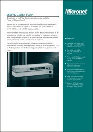
3 Finding Your Way Around<br />
LED indicator<br />
push<br />
button<br />
EAS<br />
connection<br />
(optional)<br />
back<br />
mount<br />
holes<br />
scan window<br />
host POS<br />
terminal<br />
AC adapter<br />
(optional)<br />
auxiliary scanner<br />
Figure 1: Overview<br />
4 Connecting and Mounting<br />
4.1 Power<br />
The scanner requires a minimum of 300mA at 5 Vdc power. The interface cable<br />
that comes with the scanner supports both direct power (where the scanner<br />
takes power from the host machine) and external power (that's what the supplied<br />
power adapter is for). A sufficiently robust POS system can support a<br />
scanner successfully without external power; a POS system with a barely adequate<br />
power supply may produce erratic performance (either of the POS system<br />
itself, or of the scanner, or both) when a scanner is attached. Unless you<br />
2
are sure your POS system can handle the load, it is recommended that you use<br />
the supplied power adapter. When an external adapter is connected, the scanner<br />
does not take power from the host.<br />
The scanner turns on when power is supplied, and turns off when power is<br />
removed. There is no on/off switch on the scanner itself.<br />
Use only an AC/DC power adapter approved for the scanner. Use of other<br />
power supplies may cause damage to the product, and void the factory warranty.<br />
4.2 Verifying Scanner Operation<br />
Before mounting your scanner, please follow the procedure below to verify<br />
scanning operation.<br />
1. Take out the screws and remove the mounting plate.<br />
Figure 2: Remove Mounting Plate<br />
3
2. Insert the 8-pin modular plug of the power link cable into the “host” connector<br />
in the back of the scanner until a firm click is heard.<br />
3. Plug the power adapter into the jack on the power link cable. (See Figure<br />
1.)<br />
4. Plug the AC end of the power adapter into an AC outlet. The scanner powers<br />
up, the buzzer sounds four beeps and the LED indicator glows blue.<br />
5. Present a known-good test barcode to the scanner. The scanner should<br />
issue a short beep and the LED should flash red momentarily. [If the scanner<br />
is connected to a keyboard wedge for this test, it should read one barcode,<br />
beep, then remain with a red LED indicating light. This is normal<br />
when the keyboard wedge is not connected to a live host terminal.]<br />
Note: If the scanner does not produce any beeps, or produces the wrong<br />
beeps, or the LED does not light, remove the power connection and refer to the<br />
section on Troubleshooting.<br />
4.3 Mounting<br />
After the scanner passes its verification test (Section 4.2 above), proceed with<br />
mounting.<br />
The scanner should be installed in a location away from direct sunlight; high<br />
levels of ambient light reduce scanner effectiveness.<br />
The two basic styles of mounting are a) with the included mounting plate, and<br />
b) with a custom bracket (not included) for back mounting. If an auxiliary handheld<br />
scanner is to be attached, it must be properly connected as part of the<br />
mounting process.<br />
4
Mounting Plate Installation<br />
1. Position the mounting plate in the desired location and secure it in place. If<br />
desired, use the full-size boring template in Figure 6 on page 21.<br />
2. Insert the connecting cable in the slot in the mounting plate.<br />
3. Insert the 8-pin modular plug of the power link cable into the “host” connector<br />
in the back of the scanner until a firm click is heard.<br />
5
4. Move the scanner into position on the mounting plate, engaging the tab on<br />
the underside. Be careful not to pinch the cable.<br />
Figure 3: Install Scanner on Mounting Plate<br />
5. Replace the mounting plate screws.<br />
6
Auxiliary Handheld Scanner Connection (optional)<br />
The scanner supports the operation of an auxiliary handheld scanner, which<br />
may be connected via a 10-pin RS-232 modular plug to the connector marked<br />
“aux” in the back of the scanner.<br />
1. Insert the connecting cable in the slot in the mounting plate, but reverse the<br />
cable relief molding of the scanner interface cable in the mounting plate to<br />
allow space for the auxiliary handheld scanner cable.<br />
2. Insert the 8-pin modular plug of the power link cable into the “host” connector<br />
in the back of the scanner until a firm click is heard.<br />
3. Insert the auxiliary cable connector into the 10-pin “aux” jack until it clicks<br />
and route the cable through the space above the scanner interface cable.<br />
4. Move the scanner into position on the mounting plate, engaging the tab on<br />
the underside. Be careful not to pinch any cables.<br />
5. Replace the mounting plate screws.<br />
Back Mounting<br />
If desired the scanner may be mounted to your own custom bracket using the<br />
threaded mounting holes on the back. (See Figure 1.) The mounting holes are<br />
threaded to accommodate M4 x 0.7 machine screws to a depth of 5.0 mm.<br />
Make sure your bracket design allows for the exit of the interface cable. The<br />
supplied mounting plate protects the interface cable connection, but requires<br />
that the cable exits from the back of the unit.<br />
7
4.4 Connecting to the Host<br />
The power link interface cable comes with different host-end connectors,<br />
depending on the host. Follow the steps below to connect the interface cable to<br />
the host.<br />
1. Make sure that the power of the host system is off.<br />
2. Connect the host end of the interface cable to the appropriate connector on<br />
the host system.<br />
3. For those cases where external power is used, plug the external AC power<br />
adapter into the jack on the interface cable. (See Figure 1.)<br />
4. Turn on the host system.<br />
5 Setting Up the Scanner<br />
In some cases no setup is required. The scanner is either pre programmed to<br />
suit the situation, or it auto detects and is ready to go. In other cases the scanner<br />
must be informed about what kind of system it is connected to. This can be<br />
done in a few moments using the included booklet titled Programming Guide.<br />
The Programming Guide may be used to set a number of parameters on the<br />
scanner: communication interface type (RS-232, Keyboard, USB), beep tone,<br />
sleep mode timings, same-code delay time, enable/disable decoding of numerous<br />
code types, and more advanced things like set headers and trailers.<br />
Individual parameters may be set at any time without affecting the other parameters.<br />
5.1 Scan Test<br />
1. With the scanner running (LED blue) and the host system on, try to scan<br />
several known-good barcodes.<br />
2. Check the results on the POS screen. If the scanner is reading okay, no further<br />
setup may be necessary.<br />
3. If the POS screen does not show the expected scans, go to Set Up, below.<br />
5.2 Set Up<br />
1. With the scanner running (LED blue) and the host system on, present the<br />
barcode, found on the inside cover of the<br />
8
Programming Guide, to the scanner. The scanner gives two beeps: low and<br />
high, and the LED turns red. The scanner is in programming mode.<br />
2. Decide which parameters are required and find their barcodes in the Programming<br />
Guide.<br />
3. Cover unwanted codes with your hand and present the desired codes, one<br />
by one, to the scanner. The scanner beeps once as it accepts each code.<br />
4. When done, again present the barcode.<br />
The scanner beeps twice, once long and once short, and the LED returns<br />
to blue. The scanner has been programmed.<br />
5. Test again with known-good barcodes. If results are good, you are done<br />
setting up. Otherwise, return to step 1 and try again.<br />
9
6 Operation<br />
The scanner can read barcodes in either sweep or presentation mode to<br />
accommodate different requirements. Sweep mode means moving items<br />
through the scan volume. Left to right, right to left, top to bottom, bottom to top,<br />
etc. are all okay. This scanner is truly omni directional. Sweep scanning is usually<br />
used for high throughput and reduced product handling. Presentation scanning<br />
is used where counter top space is at a premium. The product is moved<br />
toward the scan window (“presented”) until the barcode is read, then the product<br />
is removed.<br />
6.1 LED Indications<br />
A dual color red-blue LED indicates operating status as follows:<br />
Off<br />
LED status<br />
Steady blue light<br />
One red flash<br />
Steady red light<br />
Flashing blue light<br />
Steady red/blue light<br />
Alternate flashing red and<br />
blue light<br />
Indication<br />
No power supplied to the scanner.<br />
The scanner is on and ready to scan.<br />
A barcode has been successfully decoded.<br />
A barcode has been successfully decoded,<br />
but the object is not removed from the scan<br />
window.<br />
The scanner is in programming mode.<br />
The scanner is in sleep mode.<br />
This indicates the scanner has a motor or<br />
laser failure.<br />
For motor failure, a periodic beep is sounded.<br />
Return the unit for repair.<br />
The scanner detects failing power. Please<br />
check the power supply.<br />
10
6.2 Beeps<br />
A beeper gives audible feedback on scanner operation.<br />
One beep<br />
Beeps<br />
Four beeps in series<br />
Two beeps: low-high<br />
Two beeps: same tone<br />
Continuous tone<br />
6.3 Changing the Beep Volume<br />
The scanner can be programmed with the Programming Guide to change<br />
beeper tone, volume and duration; the beeper volume can also be changed by<br />
using the push button.<br />
The default beep volume is loud. There are three sound levels: loud, medium,<br />
and low.<br />
Press and hold the push button for about 5 seconds. The scanner will cycle to<br />
its next level. Repeat till the desired level is reached.<br />
Note: The volume setting is saved in volatile memory. That means the change<br />
will lost when the scanner powers down. On next power up the scanner resets<br />
to the configured setting. If you wish to keep the changed the volume setting,<br />
use the Programming Guide to set the changes.<br />
6.4 Sleep Mode<br />
Indication<br />
A barcode has been successfully decoded.<br />
This indicates the scanner passed the power<br />
on self-test and is operating properly.<br />
The scanner has entered programming<br />
mode.<br />
Scanner has returned from programming to<br />
normal mode.<br />
This is a failure indication. Return the unit for<br />
repair.<br />
After the scanner has been inactive for a period of time, the laser automatically<br />
turns off; after some more time, the motor turns off and the scanner enters<br />
“sleep mode,” indicated by the blue status LED blinking once a second. To<br />
wake up the unit, simply present an object close to the scanner window, or<br />
press the push button.<br />
Note: The scanner includes a motion sensor that detects activity in front of the<br />
scan window. The detecting distance is up to about 50mm (2 inches) from the<br />
scan window, depending on ambient light.<br />
11
6.5 Controlling the Scanner from a POS System<br />
The scanner can be controlled from the POS system via the RS-232C interface.<br />
Control can be accomplished by transmitting the following single-byte commands<br />
to the scanner. The default settings for the commands are as follows:<br />
ASCII<br />
Code<br />
Function<br />
Byte is Also<br />
Called:<br />
OE Hex enable (resumes from disable) Shift Out or <br />
OF Hex disable Shift In or <br />
05 Hex power-up re-initialization ENQ or <br />
12 Hex sleep DC2 <br />
14 Hex wake up (resumes sleep) DC4 <br />
Note: When the scanner is disabled, the scanner motor will continue running<br />
until the scanner goes into sleep mode.<br />
12
7 Maintaining the Scanner<br />
The scanner is designed for long-term trouble-free operation and rarely needs<br />
any maintenance. Only an occasional cleaning of the scanner window is necessary<br />
in order to remove dirt and fingerprints.<br />
7.1 Cleaning the Scan Window<br />
Wipe the scan window with a soft lint-free cloth and a non-abrasive cleaner to<br />
avoid scratching. The scan window may be cleaned while the scanner is running.<br />
7.2 Replacing the Interface Cable<br />
The standard interface cable is attached to the scanner with an 8-pin modular<br />
connector. When properly seated, the connector is secured in the scanner handle<br />
by a flexible retention tab. The cable is designed to be field replaceable.<br />
Replacement cables can be obtained from your authorized distributor.<br />
To replace the cable, follow these steps.<br />
1. Make sure that the power of your computer system is switched off, and if a<br />
power adapter is used, disconnect it from the scanner cable.<br />
2. Disconnect the old scanner cable from the computer system.<br />
3. Remove the screws that hold the mounting plate on the scanner and disengage<br />
the mounting plate.<br />
4. Press down the small tab on the connector where the old cable is attached<br />
to the scanner and pull. The connector should come out.<br />
5. Insert the connecting cable in the slot in the mounting plate.<br />
6. Insert the 8-pin modular plug of the power link cable into the “host” connector<br />
in the back of the scanner until it clicks.<br />
7. Mate the scanner and the mounting plate, engaging the tab on the underside.<br />
Be careful not to pinch the cable.<br />
8. Replace the mounting plate screws.<br />
9. Plug the new cable into the host.<br />
10. If a power adapter is used, plug the power adapter into the jack on the interface<br />
cable.<br />
13
8 Specifications<br />
OPERATIONAL<br />
Light Source<br />
Depth of Scan Field<br />
Width of Scan Field<br />
Number of Scan Lines 32<br />
Scan Pattern<br />
Scan Speed<br />
Dual 650nm visible laser diodes<br />
0-216mm<br />
90mm @ contact, 218mm @ 216mm<br />
8-direction scan field<br />
2400 scans per second<br />
Minimum Bar Width 5mil @ PCS 90%<br />
PHYSICAL<br />
Print Contrast 30% @ UPC/EAN 100%<br />
Indicators (LED)<br />
Decode Capability<br />
Beeper Operation<br />
System Interfaces<br />
Height<br />
Depth<br />
Width<br />
Weight<br />
Cable<br />
POWER<br />
Input Voltage<br />
Power<br />
Operating Current<br />
Laser Class<br />
EMC<br />
Two-color LED (blue & red)<br />
UPC/EAN/JAN, UPC Versions A&E, EAN-8, EAN-<br />
13, JAN-8, JAN-13, ISBN/ISSN, Japanese Bookland,<br />
Code 39 (with full ASCII), Codabar (NW7),<br />
Code 128/EAN 128, Code 93, Interleaved 2 of 5,<br />
Addendum 2 or 5, MSI/Plessey, China Post Code,<br />
Code 32 (Italian Pharmacode)<br />
Optional: IATA Code, Industrial 2 of 5, Standard 2 of<br />
5, Discrete 2 of 5, Matrix 2 of 5, Code 11, RSS-14,<br />
RSS Limited, RSS Expanded<br />
Programmable tone and beep time<br />
Keyboard, RS-232C, USB1.1, Wand, Aux. RS-232<br />
152mm<br />
82mm<br />
152mm<br />
1.2kg<br />
Standard 2m straight<br />
5VDC±10%<br />
1.5 watts<br />
300mA @ 5 V<br />
CDRH: Class II a; IEC 60825-1: Class I<br />
CE & FCC DOC compliance<br />
14
ENVIRONMENT<br />
Operating Temperature 0°C - 40°C<br />
Storage Temperature -20°C - 60°C<br />
Humidity<br />
Light Level<br />
Shock<br />
5% - 95% RH (non-condensing)<br />
max. 4000 LUX (fluorescent)<br />
Designed to withstand 1m drops<br />
Specifications subject to change without notice.<br />
9 Dimensions<br />
Units: mm (inches)<br />
Figure 4: Dimensions<br />
15
top view<br />
side view<br />
Figure 5: Scan Field<br />
16
10 Pin Assignments<br />
Connecting Ports<br />
HOST Port<br />
Pin<br />
Connector Type<br />
Keyboard Wedge RS-232C<br />
1 DC + 5 V input<br />
2 Keyboard Clock N.C.<br />
3 PC Clock RTS_CMOS<br />
4 Ground<br />
5 N.C. TXD_CMOS<br />
6 N.C. RXD_CMOS<br />
7 Keyboard Data N.C.<br />
8 PC Data CTS_CMOS<br />
AUX Port<br />
Pin<br />
Function<br />
1 NC<br />
2 NC<br />
3 +5 V out. 150mA max.<br />
4 RTS_Out<br />
5 Ground<br />
6 TXD_Out<br />
7 RXD_In<br />
8 NC<br />
9 CTS_In<br />
10 NC<br />
17
11 Troubleshooting<br />
Problem<br />
The scanner is on but cannot<br />
read barcodes. The LED<br />
stays blue.<br />
The scanner is on, but the<br />
motor is not running; the<br />
facet wheel is not rotating. A<br />
barcode cannot be read. The<br />
LED is intermittently flashing<br />
blue.<br />
The LED remains red and<br />
blue.<br />
The scanner does not accept<br />
more than two or three barcode<br />
labels.<br />
Diagnostic Tips<br />
The scanner window is dirty. Clean the scanner<br />
window as described in the Maintenance<br />
section.<br />
The presented barcode type is not enabled.<br />
Use the Programming Guide to tell the scanner<br />
to accept that type of barcode.<br />
The host has disabled the scanner. Check<br />
host setup.<br />
The barcode type presented is not supported<br />
by the scanner.<br />
The scanner has entered into the sleep<br />
mode. Press the push button on the front of<br />
the scanner to wake up the scanner, or<br />
present an object close to the scan window.<br />
Possible failure of the scanning safeguard<br />
circuit. Disconnect the scanner from its power<br />
source immediately and contact your dealer.<br />
There is no proper handshaking with the POS<br />
system. Switch on the POS system and<br />
check connection and communication settings.<br />
A stray barcode is sitting somewhere in the<br />
scanner field of view. Remove all barcode<br />
labels from the scanner’s scan volume and<br />
try again.<br />
The scanner cannot send the data to the<br />
POS system. Make sure that all cables are<br />
connected and your POS system is ready to<br />
receive data.<br />
18
Problem<br />
A barcode is read by the<br />
scanner but not accepted by<br />
the POS system.<br />
Diagnostic Tips<br />
The communication cable is not connected to<br />
the correct port of your POS system. Refer to<br />
the manual of your POS system to locate the<br />
serial port.<br />
The communication settings of the system<br />
and scanner do not match. Adjust the settings<br />
so they match.<br />
The communication cable does not suit your<br />
POS system. Contact your dealer for the correct<br />
communication cable.<br />
The software running on the POS system<br />
does not support the data format of the barcode<br />
label.<br />
19
Notes<br />
20
Figure 6: Mounting Plate Boring Template<br />
21
Part no.: MUL-53251-01