panzerflex cables - Prysmian
panzerflex cables - Prysmian
panzerflex cables - Prysmian

Create successful ePaper yourself
Turn your PDF publications into a flip-book with our unique Google optimized e-Paper software.
p a l a<br />
z z<br />
o<br />
p a a z z o<br />
lPANZERFLEX CABLES<br />
p a l a<br />
z z<br />
o<br />
Leader in rubber since more than 30 years<br />
dega design group<br />
Merlino plant<br />
Sales Head Office<br />
<strong>Prysmian</strong> Cavi e Sistemi Italia srl<br />
Viale Sarca 222, 20126 Milano, Italy, tel. +39 02 6449 1, fax +39 02 6449 5882 / 4610<br />
www.prysmian.it<br />
PANZERFLEX CABLES<br />
2011<br />
FLEXIBLE POWER AND CONTROL CABLE S<br />
for mobile application and heavy duty service
pal<br />
azzo<br />
Introduction<br />
PALAZZO has a history of producing special purpose <strong>cables</strong> for special<br />
applications. For <strong>cables</strong> that will be continuously flexed, reeled, tensioned,<br />
and installed in demanding and harsh environment, PALAZZO has developed<br />
a flexible cable that excels in its use.<br />
PALAZZO PANZERFLEX is the cable and its reliability is very well known<br />
throughout the world.<br />
There is virtually no limit to the types of flexible <strong>cables</strong> that PALAZZO can<br />
produce. Specially tailored <strong>cables</strong> can be designed and manufactured<br />
according to a wide range of specific application.<br />
This specialization means the PALAZZO <strong>cables</strong> are more able to meet<br />
each customer’s particular requirements and demands than general<br />
purpose flexible <strong>cables</strong>, helping customers to improve performance while<br />
reducing down time.<br />
PALAZZO understands the needs of customers to have local approvals<br />
and actively works to carry the Marking and Approvals that are needed.<br />
For the latest technology of <strong>cables</strong> for indoor applications, PALAZZO can<br />
produce the Mobile Cable described in halogen free version, with no toxic<br />
gases and opaque fumes emission according to the most severe international<br />
standards.<br />
The product information given in this catalogue represent only a first step in<br />
introducing our cable. It is a Testament of our ongoing efforts to provide our<br />
customers with not only the best products, but also the right information.<br />
Do not hesitate to contact our Sales Office for any additional information<br />
regarding any flexible cable application you may have.<br />
Panzerflex catalogue 1
2<br />
PANZERFLEX CABLES
pal<br />
azzo<br />
Index<br />
Benefits, standards pag. 04<br />
References and quality certificates pag. 05<br />
Cable use guide pag. 07<br />
LOW VOLTAGE REELING AND FESTOONING<br />
PANZERFLEX-L 0.6/1 kV (N)SHTÖU-J / -O pag. 10<br />
PANZERFLEX-L 0.6/1 kV (N)SHTÖU-JZ/ -OZ pag. 12<br />
PANZERFLEX-SIGNAL 0.6/1 kV (N)SHTÖU-JZ/ -OZ pag. 14<br />
FLEXIFLAT 450/750 V (N)GFLGÖU pag. 16<br />
FESTOONFIBERFLEX pag. 18<br />
VERTICAL APPLICATION AND HIGH TENSILE LOAD<br />
PANZERFLEX-VS 0.6/1 kV NSHTÖU-J/ -O; NSHTÖU -JZ / OZ pag. 22<br />
PANZERLITE 0.6/1 kV pag. 24<br />
BASKET APPLICATION<br />
BASKETHEAVYFLEX 300/500 V GRDGÖU pag. 28<br />
MEDIUM VOLTAGE REELING AND FESTOONING<br />
PANZERFLEX-ELX<br />
3,6 ÷ 12/20 kV (N)TSCGEWÖU pag. 32<br />
PANZERFLEX-ELX+OF 3,6 ÷ 12/20 kV (N)TSCGEWÖU pag. 34<br />
PANZERFLAT-ELX<br />
3,6 ÷ 12/20 kV (N)3GFLCGEWÖU pag. 36<br />
TECHNICAL INFORMATION<br />
Bending Radii pag. 40<br />
Handling and installation pag. 41<br />
Electrical pag. 46<br />
Drum dimensions and weight pag. 53<br />
Panzerflex catalogue 3
PANZERFLEX CABLES<br />
Benefits<br />
According with PALAZZO philosophy and technology, the PANZERFLEX<br />
<strong>cables</strong> can offer several important benefits:<br />
. Highly duration under constant severe movable conditions;<br />
. Tinned copper conductors provide easy solder ability and corrosion resistance;<br />
. Easy stripping;<br />
. Outstanding physical and electrical properties;<br />
. Ozone resistant;<br />
. Extremely resistant to inducted twisting and corkscrewing;<br />
. Increased vertical suspension performance and conductor life;<br />
. Excellent resistance to heat, oil, gasoline, kerosene, and alkalis in both<br />
severe indoor and outdoor applications;<br />
. Short manufacturing lengths availability.<br />
Standards<br />
Our <strong>cables</strong> follow - as main line - the design regulation given by the DIN<br />
VDE standards.<br />
DIN = German Standard Institute.<br />
VDE = Association of German Electrical Engineers.<br />
Moreover, as international standards, we take into account also the UL<br />
standards<br />
UL = Underwriters Laboratories Inc.<br />
VDE<br />
REGISTERED<br />
FIRM<br />
You will find the specific reference to the standards in each cable description.<br />
4
pal<br />
azzo<br />
References<br />
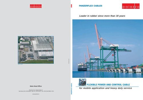
The Palazzo PANZERFLEX <strong>cables</strong> are installed on some of the fastest and<br />
tallest cranes in the today’s market.<br />
We supply some of the worldwide well known cranes producers such as<br />
SPMP, ZPMC, Hyundai, Konecranes, Krupp, Impsa, Liebherr, Mitsubishi,<br />
Samsung, Fantuzzi Reggiane.<br />
Also the major reels constructors like Cavotec/Specimas, Delachaux-Conductix,<br />
Stemmann and Wampfler are our regular customers.<br />
Our Panzerflex <strong>cables</strong> are also installed on the major harbours (Thames<br />
Port, Los Angeles, Hong Kong, Shanghai, Hamburg, Sydney, TCT Taranto,<br />
VTE Genoa, MED CENTER Gioia Tauro, etc.) and in heavy industrial facilities<br />
such as steel mills (ILVA-Riva Acciai, Techint, Arcelor), paper mills, platforms,<br />
shipyards, etc.<br />
Quality certificates<br />
Panzerflex catalogue<br />
5
6<br />
PANZERFLEX CABLES
pal<br />
azzo<br />
Cable use guide<br />
CABLE WINDING REELS<br />
festoons<br />
cable laid on ground or in conduit<br />
vertical cable<br />
cable tender<br />
systems<br />
guide pulley<br />
systems<br />
pendant push<br />
buttons<br />
cable carrier<br />
chains<br />
basket<br />
LOW VOLTAGE CABLES<br />
PANZERFLEX-L 0.6/1 kV<br />
(N)SHTÖU<br />
PANZERFLEX-VS 0.6/1 kV<br />
PANZERLITE 0.6/1 kV<br />
MEDIUM VOLTAGE CABLES<br />
PANZERFLEX-ELX up to 20 kV<br />
(N)TSCGEWÖU<br />
PANZERFLEX-ELX+FO<br />
up to 20 kV (N)TSCGEWÖU<br />
PANZERFLAT-ELX<br />
up to 10 kV<br />
OTHERS CABLES<br />
FLEXIFLAT 450/750 kV<br />
(N)GFLGÖU<br />
BASKETHEAVYFLEX<br />
300/500 kV<br />
FESTOONFIBERFLEX<br />
The above table is designed in order to give an easy reference in cable selection for the main mobile equipment application.<br />
Please keep in mind that when using this guide all the concurrent factors are to be considered: bending radii, speed, ambient<br />
temperature and tension. Even if only one of these parameters stands outside the given data of this catalogue, please contact<br />
our sales department for gaining further information.<br />
NO APPLICATION<br />
MAIN APPLICATION<br />
SUITABLE<br />
Panzerflex catalogue<br />
7
8<br />
PANZERFLEX CABLES
pal<br />
azzo<br />
Courtesy of: REGGIANE CRANES and PLANTS - FANTUZZI GROUP - Italy<br />
LOW VOLTAGE REELING AND FESTOONING<br />
Panzerflex catalogue<br />
9
PANZERFLEX CABLES<br />
Power <strong>cables</strong> in line with VDE 0250 part. 814<br />
Cable type<br />
PANZERFLEX-L 0.6/1 kV<br />
(N)SHTÖU-J / -O rubber <strong>cables</strong> suitable for reeling & festoon system<br />
Main application<br />
Flexible power <strong>cables</strong> for use on connecting movable parts of machine tools and any material handling equipment (i.e. Stacker/reclaimer,<br />
ship to shore crane, container crane festoon, grabtype ship unloading, gantry festoons, timber crane festoons, etc.).<br />
Suitable for any energy supply on cable reels and festoon systems associated to high mechanical stresses, frequent bending/torsional<br />
operation and fast movement with strong acceleration.<br />
Construction<br />
Conductor: Tinned copper conductor, flexible cl.5 IEC 60228<br />
Specially designed for mobile application<br />
Insulation:<br />
HEPR compound better than 3GI3<br />
New specially developed crushproof compound with improved electrical and mechanical characteristics<br />
Cores identification: Colours according to according to DIN VDE 0293 part 308 / HD 308 S2<br />
Standard colours:<br />
- 1 core: black<br />
- 3+3 cores: brown, black, grey + 3 green/yellow<br />
- 4 cores: green/yellow, brown, black, grey<br />
- 5 cores: green/yellow, blue, brown, black, grey<br />
Laying-up:<br />
Short lay length for better flexibilty<br />
≤7,5 times the laying-up cores diameter<br />
Separation (if any): Tape(s)<br />
Inner sheath:<br />
Polychloroprene rubber based compound<br />
Better than GM1b<br />
Antitwisting protection: Synthetic yarns<br />
Firmly bonded between inner and outer sheath<br />
Outer sheath:<br />
Black polychloroprene rubber compound<br />
UV resistant oil and chemical resistant better then 5GM2<br />
Marking:<br />
PALAZZO - PANZERFLEX-L 0,6/1 kV nc x cross section<br />
Parameters<br />
Electrical<br />
Thermal<br />
Mechanical<br />
Rated voltage<br />
Uo/U= 0,6/1 kV<br />
Maximum permissible operating voltage in AC systems Um = 1,2 kV<br />
AC test voltage over 5 minutes<br />
3,5 kV<br />
Current Carrying Capacity According to DIN VDE 0298 part 4<br />
Fully flexible operation - 25 °C<br />
Fixed installation - 40 °C<br />
Maximum permissible operating temperature of the conductor 90 °C<br />
Short-circuit temperature of the conductor 250 °C<br />
Tensile load Up to 20 N/mm 2<br />
Minimum bending radii According to DIN VDE 0298 part 3<br />
Reeling operation<br />
No restriction. Consult the manufacturer<br />
if speed exceeds 180 m/min<br />
Festoon systems<br />
Up to 240 m/min<br />
Chemical<br />
Resistance to oil<br />
Weather resistance<br />
According to VDE / IEC standard<br />
Unrestricted use outdoor and indoor,<br />
UV resistant, moisture resistant.<br />
If the environment reaches – 40 °C, Palazzo can provide a special version of this cable (differentiated from the standard one by the “-K” add<br />
to the code name), which is constructed with a special rubber compound that can face this condition.<br />
For temperature down to – 40 °C we suggest to use the Panzerflex-K. To allow this cable operating at – 40°C we use an outer-sheath<br />
compound that is less resistant to abrasion and tear so please contact our sales department for more information regarding application.<br />
10
Low Voltage Reeling and Festooning<br />
p a l a z z o<br />
Power <strong>cables</strong> in line with<br />
VDE 0250 part. 814<br />
Table Table 1: -0.6/1kV, 1: PANZERFLEX-L unarmoured 0.6/1 <strong>cables</strong> kV (N)SHTÖU-J /-O power <strong>cables</strong><br />
N. of cores and<br />
nominal<br />
section<br />
(n•mm 2 )<br />
Main conductor<br />
D.C. resist. nom. diam.<br />
at 20 °C<br />
Ohm/km mm<br />
Splitted protec.<br />
earth cond.<br />
nom. diam.<br />
mm<br />
Overall diameter Net weight Maximum<br />
Current carrying capacity at 30 °C *<br />
min. max. approx. permissible<br />
Suspended Spiral or<br />
mm mm kg/km<br />
tensile force<br />
N<br />
Laid straight<br />
A<br />
in free air<br />
A<br />
1 layer<br />
A<br />
2 layer<br />
A<br />
3 layer<br />
A<br />
Short circuit<br />
current<br />
80 ° to 200 °C<br />
kA•1 sec.<br />
1x16 1,24 5,4 10,6 12,7 265 240 141 148 - - - 2,0<br />
1x25 0,795 6,6 12,2 14,3 370 375 187 196 - - - 3,2<br />
1x35 0,565 8,0 13,9 15,9 505 525 231 243 - - - 4,5<br />
1x50 0,393 9,3 15,6 17,7 650 750 288 302 - - - 6,4<br />
1x70 0,277 11,2 17,6 19,7 875 1050 357 375 - - - 9,0<br />
1x95 0,210 13,0 20,0 22,1 1120 1425 430 452 - - - 12,2<br />
1x120 0,164 15,0 22,2 24,3 1440 1800 503 528 - - - 15,4<br />
1x150 0,132 16,9 24,9 27,0 1730 2250 577 606 - - - 19,2<br />
1x185 0,108 18,3 26,7 28,8 2070 2775 658 691 - - - 23,7<br />
1x240 0,0817 20,5 29,0 32,2 2660 3600 771 810 - - - 30,7<br />
3x4 5,09 2,4 14,9 17,0 395 240 41 43 33 25 20 0,51<br />
3x6 3,39 3,1 17,2 19,3 525 360 53 56 42 32 26 0,77<br />
3x10 1,95 4,2 20,3 22,4 765 600 74 78 59 45 36 1,3<br />
3x16 1,24 5,4 23,6 25,7 1080 960 99 104 79 60 49 2,0<br />
3x25 0,795 6,6 27,0 29,1 1470 1500 131 138 105 80 64 3,2<br />
3x35 0,565 8,0 30,4 33,6 2030 2100 162 170 130 99 79 4,5<br />
3x50 0,393 9,3 35,4 38,6 2680 3000 202 212 162 123 99 6,4<br />
3x70 0,277 11,2 39,6 42,8 3530 4200 250 263 200 153 123 9,0<br />
3x95 0,210 13,0 43,8 47,0 4400 5700 301 316 241 184 147 12,2<br />
3x120 0,164 15,0 49,0 53,5 5730 7200 352 370 282 215 172 15,4<br />
3x150 0,132 16,9 55,5 60,0 7040 9000 404 424 323 246 198 19,2<br />
3x185 0,108 18,3 59,5 64,0 8320 11100 461 484 369 281 226 23,7<br />
3x240 0,0817 20,5 67,5 72,0 10850 14400 540 567 432 329 265 30,7<br />
4x4 5,09 2,4 16,0 18,1 460 320 41 43 33 25 20 0,51<br />
4x6 3,39 3,1 18,4 20,5 615 480 53 56 42 32 26 0,77<br />
4x10 1,95 4,2 21,9 24,0 920 800 74 78 59 45 36 1,3<br />
4x16 1,24 5,4 25,5 27,6 1310 1280 99 104 79 60 49 2,0<br />
4x25 0,795 6,6 29,6 32,8 1860 2000 131 138 105 80 64 3,2<br />
4x35 0,565 8,0 33,2 36,4 2490 2800 162 170 130 99 79 4,5<br />
4x50 0,393 9,3 38,4 41,6 3300 4000 202 212 162 123 99 6,4<br />
4x70 0,277 11,2 43,6 46,8 4420 5600 250 263 200 153 123 9,0<br />
4x95 0,210 13,0 48,5 53,0 5610 7600 301 316 241 184 147 12,2<br />
4x120 0,164 15,0 55,5 60,0 7360 9600 352 370 282 215 172 15,4<br />
4x150 0,132 16,9 61,0 65,5 8770 12000 404 424 323 246 198 19,2<br />
4x185 0,108 18,3 67,5 72,0 10730 14800 461 484 369 281 226 23,7<br />
4x240 0,0817 20,5 74,0 78,5 13560 19200 540 567 432 329 265 30,7<br />
5x4 5,09 2,4 18,0 20,1 575 400 41 43 33 25 20 0,51<br />
5x6 3,39 3,1 19,8 21,9 725 600 53 56 42 32 26 0,77<br />
5x10 1,95 4,2 24,5 26,6 1140 1000 74 78 59 45 36 1,3<br />
5x16 1,24 5,4 27,6 29,7 1550 1600 99 104 79 60 49 2,0<br />
5x25 0,795 6,6 32,2 35,4 2170 2500 131 138 105 80 64 3,2<br />
5x35 0,565 8,0 37,0 40,2 3080 3500 162 170 130 99 79 4,5<br />
5x50 0,393 9,3 42,2 45,4 4010 5000 202 212 162 123 99 6,4<br />
5x70 0,277 11,2 48,0 52,5 5480 7000 250 263 200 153 123 9,0<br />
5x95 0,210 13,0 54,5 59,0 7010 9500 301 316 241 184 147 12,2<br />
3x50+3x25/3 0,393 9,3 4,0 34,2 37,4 2730 3000 202 212 1 62 123 99 6,4<br />
3x70+3x35/3 0,277 11,2 4,9 39, 6 42,8 3740 4200 250 263 200 153 123 9,0<br />
3x95+3x50/3 0,210 13,0 5,4 43,8 47,0 4 690 5700 301 316 241 184 147 12,2<br />
3x120+3x70/3 0,1 64 15,0 6,6 49,5 54,0 6220 7200 352 370 282 215 172 15,4<br />
3x150+3x70/3 0,132 1 6,9 6,6 55,5 60,0 7480 9000 404 424 323 246 198 19,2<br />
3x185+3x95/3 0,108 18,3 8,0 59,5 64,0 9020 11100 461 484 369 281 226 23,7<br />
3x240+3x120/3 0,0817 20,5 9,3 67,5 72,0 11760 14400 540 567 432 329 265 30,7<br />
4x10+4x2.5 1,95 4,2 23,2 25,3 1060 80 74 78 59 45 36 1,3<br />
4x16+4x2.5 1,24 5,4 25,5 27,6 1360 1280 99 104 79 60 4 2,0<br />
4x25+4x2.5 0,795 6,6 29,6 32,8 1910 2000 131 138 105 80 64 3,2<br />
4x35+4x2.5 0,565 8,0 32,8 36,0 2530 2800 162 170 130 99 79 4,5<br />
4x50+4x4 0,393 9,3 38,0 41,2 3370 4000 202 212 162 123 99 6,4<br />
*Tabulated values are valid up to three loaded conductors with or without earth<br />
Panzerflex catalogue<br />
11
PANZERFLEX CABLES<br />
Control <strong>cables</strong> in line with<br />
VDE 0250 part. 814<br />
Cable type<br />
PANZERFLEX-L 0.6/1 kV<br />
(N)SHTÖU-JZ / -OZ rubber <strong>cables</strong> suitable for reeling & festoon system<br />
Main application<br />
Flexible control <strong>cables</strong> for use on connecting movable parts of machine tools and any material handling equipment (i.e. Stacker/reclaimer,<br />
ship to shore crane, container crane, festoon, grabtype ship unloading, gantry festoons, timber crane festoons, etc.).<br />
Suitable for signalling supply on cable reels and festoon systems associated to high mechanical stresses, frequent bending/torsional<br />
operation and fast movement with strong acceleration.<br />
Construction<br />
Conductor: Tinned copper conductor, flexible cl.5 IEC 60228<br />
Specially designed for mobile application<br />
Insulation:<br />
HEPR compound better than 3GI3<br />
New specially developed crushproof compound with improved electrical and mechanical characteristics<br />
Cores identification: Black with printed numbers with or without 1 green/yellow<br />
Standard: with green/yellow core in the outer layer<br />
Laying-up:<br />
Short lay length for better flexibilty<br />
≤7,5 times the laying-up cores diameter in maximum 3 layer<br />
Separation (if any): Tape(s)<br />
Inner sheath:<br />
Polychloroprene rubber based compound<br />
Better than GM1b<br />
Antitwisting protection: Synthetic yarns<br />
Firmly bonded between inner and outer sheath<br />
Outer sheath:<br />
Black polychloroprene rubber compound<br />
UV resistant, oil and chemical rsistant better then 5GM2<br />
Marking:<br />
PALAZZO - PANZERFLEX-L 0,6/1 kV nc x cross section<br />
Parameters<br />
Electrical<br />
Thermal<br />
Mechanical<br />
Rated voltage<br />
Uo/U= 0,6/1 kV<br />
Maximum permissible operating voltage in AC systems Um = 1,2 kV<br />
AC test voltage over 5 minutes<br />
3,5 kV<br />
Current Carrying Capacity According to DIN VDE 0298 part 4<br />
Fully flexible operation - 25 °C<br />
Fixed installation - 40 °C<br />
Maximum permissible operating temperature of the conductor 90 °C<br />
Short-circuit temperature of the conductor 250 °C<br />
Tensile load Up to 15 N/mm 2<br />
Minimum bending radii According to DIN VDE 0298 part 3<br />
Reeling operation<br />
No restriction. Consult the manufacturer<br />
if speed exceeds 180 m/min<br />
Festoon systems<br />
Up to 240 m/min<br />
Chemical<br />
Resistance to oil<br />
Weather resistance<br />
According to VDE / IEC standard<br />
Unrestricted use outdoor and indoor,<br />
UV resistant, moisture resistant.<br />
If the environment reaches – 40 °C, Palazzo can provide a special version of this cable (differentiated from the standard one by the “-K” add<br />
to the code name), which is constructed with a special rubber compound that can face this condition.<br />
For temperature down to – 40 °C we suggest to use the Panzerflex-K. To allow this cable operating at – 40°C we use an outer-sheath<br />
compound that is less resistant to abrasion and tear so please contact our sales department for more information regarding application.<br />
12
Low Voltage Reeling and Festooning<br />
p a l a z z o<br />
Control <strong>cables</strong> in line with<br />
VDE 0250 part. 814<br />
Table Table 1: -0.6/1kV, 1: PANZERFLEX-L unarmoured 0.6/1 <strong>cables</strong> kV (N)SHTÖU-JZ / -OZ control <strong>cables</strong><br />
N. of cores<br />
and nominal<br />
section<br />
(n•mm 2 )<br />
Conductor<br />
D.C. resist. nom. diam.<br />
at 20 °C<br />
Ohm/km mm<br />
Overall diameter Net weight Maximum<br />
Current carrying capacity at 30 °C *<br />
min. max. approx. permissible<br />
Suspended Spiral or<br />
mm mm kg/km<br />
tensile force<br />
N<br />
Laid straight<br />
A<br />
in free air<br />
A<br />
1 layer<br />
A<br />
2 layer<br />
A<br />
3 layer<br />
A<br />
Short circuit<br />
current<br />
80 ° to 200 °C<br />
kA•1 sec.<br />
3x1.5 13,7 1,5 12,4 14,5 255 68 23 24 18 14 11 0,19<br />
4x1.5 13,7 1,5 13,1 15,2 285 90 23 24 18 14 11 0,19<br />
5x1.5 13,7 1,5 14,0 16,0 320 113 23 24 18 14 11 0,19<br />
7x1.5 13,7 1,5 15,8 17,9 415 158 23 24 18 14 11 0,19<br />
12x1.5 13,7 1,5 19,1 21,2 585 270 23 24 18 14 11 0,19<br />
18x1.5 13,7 1,5 21,6 23,7 765 405 23 24 18 14 11 0,19<br />
24x1.5 13,7 1,5 25,6 27,6 1040 540 23 24 18 14 11 0,19<br />
30x1.5 13,7 1,5 26,6 28,7 1140 675 23 24 18 14 11 0,19<br />
36x1.5 13,7 1,5 28,6 31,8 1370 810 23 24 18 14 11 0,19<br />
3x2.5 8,21 2,0 13,4 15,5 310 113 30 32 24 18 15 0,32<br />
4x2.5 8,21 2,0 14,3 16,3 355 150 30 32 24 18 15 0,32<br />
5x2.5 8,21 2,0 15,2 17,3 410 188 30 32 24 18 15 0,32<br />
7x2.5 8,21 2,0 18,1 20,2 570 263 30 32 24 18 15 0,32<br />
12x2.5 8,21 2,0 21,1 23,2 760 450 30 32 24 18 15 0,32<br />
18x2.5 8,21 2,0 24,7 26,8 1070 675 30 32 24 18 15 0,32<br />
24x2.5 8,21 2,0 28,6 31,8 1450 900 30 32 24 18 15 0,32<br />
30x2.5 8,21 2,0 30,0 33,0 1600 1125 30 32 24 18 15 0,32<br />
36x2.5 8,21 2,0 31,8 35,0 1850 1350 30 32 24 18 15 0,32<br />
7x4 5,09 2,4 20,6 22,6 760 420 41 43 33 25 20 0,51<br />
12x4 5,09 2,4 25,0 27,0 1085 720 41 43 33 25 20 0,51<br />
18x4 5,09 2,4 28,4 30,4 1460 1080 41 43 33 25 20 0,51<br />
*Tabulated values are valid up to three loaded conductors with or without earth.<br />
Derating factor shall be used for multicore <strong>cables</strong> depending on loaded conductors. See page 49.<br />
The Tensile Load on control <strong>cables</strong> is calculated considering the limit of 15N/mm 2 instead of the standard 20N/mm 2 . This is due to the construction of these multi-core <strong>cables</strong>. For higher Tensile Load<br />
please consider to use our VS type as it is provided of a central Kevlar ® strainer that allows much higher tensile loads.<br />
Panzerflex catalogue<br />
13
PANZERFLEX CABLES<br />
Signal and control <strong>cables</strong> in line with<br />
VDE 0250 part. 814<br />
Cable type<br />
PANZERFLEX-SIGNAL 0.6/1 kV<br />
(N)SHTÖU-JZ / -OZ suitable for festoon system and simple reeeling operation<br />
Main application<br />
Flexible signal/control for use on connecting movable parts of machine tools and any material handling equipment<br />
Suitable for signalling supply on festoon systems with fast movement with strong acceleration, suitable also for simple reeling.<br />
Construction<br />
Conductor: Tinned copper conductor, flexible cl.5 IEC 60228<br />
Specially designed for mobile application<br />
Insulation:<br />
EPR compound better than 3GI3<br />
Specially developed crushproof compound with improved electrical and mechanical characteristics<br />
Cores identification: Black with printed numbers with or without 1 green/yellow<br />
Each cores consecutively numbered<br />
Shield (on single core or pair): Tinned copper braid screen<br />
At least 70 % on cores<br />
At least 80 % on pairs<br />
Pairs (if any):<br />
Two cores layed-up<br />
Textile filler in the interstices to mantein good geometrical characteristics<br />
Laying-up:<br />
Short lay length for better flexibilty<br />
≤7 times the laying-up cores diameter (in maximum 3 layer for multicores <strong>cables</strong>)<br />
Separation (if any): Tape(s)<br />
Inner sheath:<br />
Polychloroprene rubber based compound<br />
Better than GM1b<br />
Antitwisting protection: Synthetic yarns<br />
Firmly bonded between inner and outer sheath<br />
Outer sheath:<br />
Black polychloroprene rubber compound<br />
UV resistant oil and chemical resistant better then 5GM2<br />
Marking:<br />
PALAZZO - PANZERFLEX 0,6/1 kV n. of cores/pairs x cross section<br />
Parameters<br />
Electrical<br />
Thermal<br />
Mechanical<br />
Rated voltage<br />
Uo/U= 0,6/1 kV<br />
Maximum permissible operating voltage in AC systems<br />
Um = 1,2 kV<br />
AC test voltage over 5 minutes<br />
2,5 kV<br />
Current Carrying Capacity According to DIN VDE 0298 part 4<br />
Bus compatbility<br />
Cable with twisted and individually shielded<br />
pairs can be used for bus systems<br />
Fully flexible operation - 25 °C<br />
Fixed installation - 40 °C<br />
Maximum permissible operating temperature of the conductor 90 °C<br />
Short-circuit temperature of the conductor 250 °C<br />
Tensile load Up to 15 N/mm 2<br />
Minimum bending radii According to DIN VDE 0298 part 3<br />
Reeling operation<br />
Up to 60 m/min<br />
Festoon systems<br />
Up to 180 m/min<br />
Chemical<br />
Resistance to oil<br />
Weather resistance<br />
According to VDE / IEC standard<br />
Unrestricted use outdoor and indoor,<br />
UV resistant, moisture resistant.<br />
If the environment reaches – 40 °C, Palazzo can provide a special version of this cable (differentiated from the standard one by the “-K” add<br />
to the code name), which is constructed with a special rubber compound that can face this condition.<br />
For temperature down to – 40 °C we suggest to use the Panzerflex-K. To allow this cable operating at – 40°C we use an outer-sheath<br />
compound that is less resistant to abrasion and tear so please contact our sales department for more information regarding application.<br />
14
Low Voltage Reeling and Festooning<br />
pal<br />
azzo<br />
Signal and control <strong>cables</strong> in line with<br />
VDE 0250 part. 814<br />
Table Table 1: -0.6/1kV, 1: PANZERFLEX-signal unarmoured <strong>cables</strong> 0.6/1 kV (N)SHTÖU-JZ / -OZ<br />
N. of cores and<br />
nominal<br />
section<br />
(n•mm 2 )<br />
Conductor<br />
D.C. resist. nom. diam.<br />
at 20 °C<br />
Ohm/km mm<br />
Overall diameter Net weight Maximum<br />
Current carrying capacity at 30 °C *<br />
min. max. approx. permissible<br />
Suspended Spiral or<br />
mm mm kg/km<br />
tensile force<br />
N<br />
Laid straight<br />
A<br />
in free air<br />
A<br />
1 layer<br />
A<br />
2 layer<br />
A<br />
3 layer<br />
A<br />
Short circuit<br />
current<br />
80 ° to 200 °C<br />
kA•1 sec.<br />
3x(2x1.0)C 20,0 1,3 20,9 23,0 670 90 - - - - - 0,13<br />
3x(2x1.5)C 13,7 1,5 21,4 23,5 740 135 - - - - - 0,19<br />
6x(2x1.0)C 20,0 1,3 26,9 29,0 1080 180 - - - - - 0,13<br />
6x(2x1.5)C 13,7 1,5 28,3 30,3 1210 270 - - - - - 0,19<br />
6x(2x2.5)C 8,21 2 30,6 33,6 1570 450 - - - - - 0,32<br />
19x2,5+5x1(c ) 8,21 2 30,6 33,8 1580 713 30 32 24 18 15 0,32<br />
19x2,5+5x1,5(c ) 8,21 2 30,6 33,8 1630 713 30 32 24 18 15 0,32<br />
25x2,5+5x1(c ) 8,21 2 32,6 35,8 1820 938 30 32 24 18 15 0,32<br />
25x2,5+5x1,5(c ) 8,21 2 32,6 35,8 1850 938 30 32 24 18 15 0,32<br />
26x2,5+10x1(c ) 8,21 2 36,2 39,4 2150 975 30 32 24 18 15 0,32<br />
*Tabulated values are valid up to three loaded conductors with or without earth.<br />
Derating factor shall be used for multicore <strong>cables</strong> depending on loaded conductors. See page 49.<br />
The Tensile Load on control <strong>cables</strong> is calculated considering the limit of 15N/mm 2 instead of the standard 20N/mm 2 . This is due to the construction of these multi-core <strong>cables</strong>. For higher Tensile Load<br />
please consider to use our VS type as it is provided of a central Kevlar ® strainer that allows much higher tensile loads.<br />
Panzerflex catalogue<br />
15
PANZERFLEX CABLES<br />
Flexible power and control flat <strong>cables</strong> in line with<br />
CEI 20-19 part.4<br />
Cable type<br />
FLEXIFLAT 450/750 V<br />
(N)GFLGÖU- J/ (N)GFLGÖU- JZ flat rubber <strong>cables</strong> for festoon system<br />
Main application<br />
Flexible power and control <strong>cables</strong> for use on connecting movable parts of machine tools and any material handling equipment.<br />
Suitable for power and signalling supply on festoon systems with fast movement with strong acceleration.<br />
Construction<br />
Conductor: Plain or tinned copper conductor, flexible to IEC 60228 cl.6 up to 6 mm 2 , cl. 5 from 10 mm 2<br />
Specially designed for mobile application<br />
Insulation:<br />
EPR compound better than 3GI3<br />
Specially developed compound with improved electrical and mechanical characteristics<br />
Cores identification: Colours according to HD 308 S2<br />
Standard colours:<br />
- 4 cores: green/yellow, brown, black, grey<br />
- ≥ 6 cores: black with printed numbers + green/yellow<br />
Green/yellow approximatly in the middle<br />
Core arrangement: Parallel, starting from 12 cores in parallel bundle<br />
Green/yellow approximatly in the middle of the cable<br />
Separation (if any): Tape(s)<br />
Outer sheath:<br />
Black polychloroprene rubber compound<br />
UV resistant, oil and chemical resistant better then 5GM2<br />
Marking:<br />
PALAZZO - FLEXIFLAT 450/750 V n. of cores x cross section<br />
Parameters<br />
Electrical<br />
Thermal<br />
Mechanical<br />
Rated voltage<br />
Uo/U = 450/750 V<br />
Maximum permissible operating voltage in AC systems<br />
Um = 900 V<br />
AC test voltage over 5 minutes<br />
2,5 kV<br />
Current Carrying Capacity According to DIN VDE 0298 part 4<br />
Bus compatibility<br />
Cable with twisted and individually<br />
shielded pairs can be used for bus systems<br />
Fully flexible operation - 25 °C<br />
Fixed installation - 40 °C<br />
Maximum permissible operating temperature of the conductor 90 °C<br />
Short-circuit temperature of the conductor 250 °C<br />
Tensile load Up to 15 N/mm 2<br />
Minimum bending radii According to DIN VDE 0298 part 3<br />
Reeling operation<br />
NO APPLICATION<br />
Festoon systems<br />
Up to 180 m/min<br />
Chemical<br />
Resistance to oil<br />
Weather resistance<br />
According to VDE / IEC standard<br />
Unrestricted use outdoor and indoor,<br />
UV resistant, moisture resistant.<br />
16
Low Voltage Reeling and Festooning<br />
Flexible power and control flat <strong>cables</strong> in line with<br />
pal<br />
azzo<br />
CEI 20-19 part.4<br />
Table Table 1: -0.6/1kV, 1: FLEXIFLAT unarmoured 450/750 <strong>cables</strong> V (N)GFLGÖU-JZ<br />
N. of cores and<br />
nominal cross section<br />
(n•mm 2 )<br />
Nominal<br />
conductor diameter<br />
(mm 2 )<br />
Max. D. C. electr.<br />
res. at 20 °C<br />
(Ohm/km)<br />
Nominal overall dimensions<br />
WixTh<br />
(mm)<br />
Weight<br />
for 1000 m<br />
(kg/km)<br />
Max. permissible<br />
tensile load<br />
(N)<br />
3 x 4 x 1.5 1.5 13.7 15 x 35 810 270<br />
4 x 4 x 1.5 1.5 13.7 15 x 45 1055 360<br />
3 x 4 x 2.5 2.0 8.21 17 x 41 1125 450<br />
4 x 4 x 2.5 2.0 8.21 17 x 53 1465 600<br />
4 x 10 4.2 1.95 11 x 35 870 600<br />
4 x 16 5.4 1.24 13 x 41 1250 960<br />
4 x 25 6.7 0.795 14,9 x 48 1785 1500<br />
4 x 35 8.2 0.565 16,8 x 52 2330 2100<br />
4 x 50 9.6 0.393 19,5 x 61 3200 3000<br />
4 x 70 11.6 0.277 22 x 70 4280 4200<br />
4 x 95 13.2 0.210 24 x 79 5550 5700<br />
With integrated fibre-optics on request<br />
Panzerflex catalogue<br />
17
PANZERFLEX CABLES<br />
Festoonfiberflex loose tube optical cable for data transmission<br />
Cable type<br />
FESTOONFIBERFLEX<br />
Rubber sheathed flexible fibre-optics cable<br />
Main application<br />
Flexible signal and data trasmission <strong>cables</strong> for use on cranes and material handling equipment,suitable for use on festoon systems, simple reeling<br />
Fibre-optics for absolute immunity from electrical interferences.<br />
Construction<br />
Fibre optics:<br />
Tubes:<br />
Cores identification:<br />
Tubes arrengement:<br />
Antitwisting protection:<br />
Outer sheath:<br />
Marking:<br />
Core diameter: 50 µm, 62,5 µm, 9µm.<br />
Cladding 125 µm, coating 250 µm<br />
Main type 62,5/125, the others on request<br />
Basic material PBTF<br />
Hollow core with filling compond<br />
Color code for tubes (pilot directional system)<br />
Different fibre colour in case of 2 o 3 fibres per tube<br />
Six tubes specially laid-up around a central support element<br />
- main construction 6 fibre-optics (1 fibre per tube)<br />
- on request 12, 18 fibre-optics (2 or 3 fibres per tube)<br />
Double layer of synthetic yarns af aramidic fibres<br />
Black polychloroprene based compound<br />
UV resistant, oil and chemical resistant better then 5GM2 compound<br />
PALAZZO - FESTOONFIBERFLEX n. of fibres & type<br />
Parameters<br />
Optical<br />
Thermal<br />
Graded index fibre Single mode fibre<br />
Fiber type 50/125 62,5 /125 E9/125<br />
Max attenuation at 850 nm dB/km 2,8 3,0 -<br />
Max attenuation at 1300 nm dB/km 0,8 0,9 0,4<br />
Max attenuation at 1550 nm dB/km - -<br />
0,3<br />
Bandwidth at 850 / 1300 nm MHz ≥ 400/800 ≥ 160/500 -<br />
Numerical aperture 0,200 ± 0,02 0,275 ± 0,02 -<br />
Mode field diameter at 1310 nm µm - - 9,2 ± 0,4<br />
Chromatic dispersion<br />
at 1300 nm ps/(nm x km) - - < 3,5<br />
at 1550 nm ps/(nm x km) - - < 18<br />
Fully flexible operation - 20 °C to +60 °C<br />
Fixed installation - 40 °C to +80 °C<br />
Mechanical<br />
Chemical<br />
Tensile load<br />
Minimum bending radii<br />
Reeling operation<br />
Festoon /cable tender systems<br />
Resistance to oil<br />
Weather resistance<br />
1200 N max<br />
200 mm<br />
Up to 120 m/min<br />
(NO RANDOM WOUND REEL)<br />
Up to 240 m/min<br />
According to VDE / IEC standard<br />
Unrestricted use outdoor and indoor,<br />
UV resistant, moisture resistant.<br />
18
Low Voltage Reeling and Festooning<br />
pal<br />
azzo<br />
Festoonfiberflex loose tube optical cable for data transmission<br />
Table Table 1: -0.6/1kV, 1: FESTOONFIBERFLEX<br />
unarmoured <strong>cables</strong><br />
N. of fibers<br />
and dimension<br />
Fibre x tubes<br />
(n)<br />
min. value<br />
mm<br />
Overall diameter<br />
max. value<br />
mm<br />
Net weight<br />
approx.<br />
kg/km<br />
Max. permissible<br />
tensile force<br />
N<br />
*Main type<br />
6G62,5/125* 1 13,0 15,0 230 1200<br />
6G50/125 1 13,0 15,0 230 1200<br />
6E9/125 1 13,0 15,0 230 1200<br />
12G62,5/125 2 13,0 15,0 230 1200<br />
12G50/125 2 13,0 15,0 230 1200<br />
12E9/125 2 13,0 15,0 230 1200<br />
18G62,5/125 3 13,5 15,5 230 1200<br />
18G50/125 3 13,5 15,5 230 1200<br />
18E9/125 3 13,5 15,5 230 1200<br />
Panzerflex catalogue<br />
19
20<br />
PANZERFLEX CABLES
pal<br />
azzo<br />
VERTICAL APPLICATION AND HIGH TENSILE LOAD<br />
Panzerflex catalogue<br />
21
PANZERFLEX CABLES<br />
Power and control <strong>cables</strong> for extreme application according to VDE 0250 part. 814<br />
Cable type<br />
PANZERFLEX-VS 0.6/1 kV<br />
NSHTÖU-J/ -O; NSHTÖU -JZ / OZ tough rubber sheathed cable<br />
Main application<br />
Extra heavy duty power and control <strong>cables</strong>. For application with high mechanical stresses<br />
(i.e.: tensile and torsion simoultaneously applied).<br />
These <strong>cables</strong> have a tensile load of minimum 2000 N (standard for control <strong>cables</strong>) and are indicated to be used on equipment such as<br />
container crane spreader reels, rack and pinion elevators using shave guided <strong>cables</strong>, pendant station, all tenders etc.<br />
Construction<br />
Conductor: Tinned copper conductor, extraflexible cl.6 IEC 60228 up to 6 mm 2 , flexible cl.5 IEC 60228 from 10 mm 2<br />
Both the class of conductors are specially designed for mobile application<br />
Insulation:<br />
EPR compound better than 3GI3<br />
special compound with improved electrical and mechanical characteristics<br />
Cores identification: Colours according to according to DIN VDE 0293 part 308 / HD 308 S2<br />
Standard colours:<br />
- 4 cores: green/yellow, brown, black, grey<br />
- 5 cores: green/yellow, blue, brown, black, grey<br />
- ≥ 6 cores: black with printed numbers, green/yellow in the outer layer<br />
Central strainer (if any): Made of aramidic yarns<br />
To be used as support element<br />
Laying-up:<br />
Short lay length for better flexibilty<br />
≤ 6,5 times the laying-up cores diameter in maximum 3 layer (for control <strong>cables</strong>)<br />
Separation (if any): Tape(s)<br />
Inner sheath:<br />
Polychloroprene rubber based compound<br />
Better than 5GM2<br />
Antitwisting protection: Textile braid of synthetic yarns<br />
Firmly vulcanized bonded between inner and outer sheath<br />
Outer sheath:<br />
Yellow polychloroprene rubber compound<br />
Oil and chemical resistant, 5GM3/5GM5 abrasion and notch resistant<br />
Marking:<br />
PALAZZO - PANZERFLEX-VS 0,6/1 kV n. of cores x cross section<br />
Parameters<br />
Electrical<br />
Thermal<br />
Mechanical<br />
Rated voltage<br />
Uo/U= 0,6/1 kV<br />
Maximum permissible operating voltage in AC systems Um = 1,2 kV<br />
AC test voltage over 5 minutes<br />
3,5 kV<br />
Current Carrying Capacity According to DIN VDE 0298 part 4<br />
Fully flexible operation - 25 °C<br />
Fixed installation - 40 °C<br />
Maximum permissible operating temperature of the conductor 90 °C<br />
Short-circuit temperature of the conductor 250 °C<br />
Tensile load Up to 20 N/mm 2<br />
with a minimum of 2000 N<br />
Minimum bending radii According to DIN VDE 0298 part 3<br />
Reeling operation<br />
No restriction. Consult the manufacturer<br />
if speed exceeds 180 m/min<br />
Chemical<br />
Resistance to oil<br />
Weather resistance<br />
According to VDE / IEC standard<br />
Unrestricted use outdoor and indoor,<br />
UV resistant, moisture resistant.<br />
22
Vertical Application and High Tensile Load<br />
pal<br />
azzo<br />
Power and control <strong>cables</strong> for extreme application according to VDE 0250 part. 814<br />
Table Table 1: -0.6/1kV, 1: PANZERFLEX-VS unarmoured 0.6/1 <strong>cables</strong> kV NSHTÖU -J / -O; NSHTÖU -JZ / OZ<br />
N. of cores<br />
and nominal<br />
section<br />
(n•mm 2 )<br />
Conductor<br />
D.C. resist. nom. diam.<br />
at 20 °C<br />
Ohm/km mm<br />
Overall diameter Net weight Maximum<br />
Current carrying capacity at 30 °C *<br />
min. max. approx. permissible<br />
Suspended Spiral or<br />
mm mm kg/km<br />
tensile force<br />
N<br />
Laid straight<br />
A<br />
in free air<br />
A<br />
1 layer<br />
A<br />
2 layer<br />
A<br />
3 layer<br />
A<br />
Short circuit<br />
current<br />
80 ° to 200 °C<br />
kA•1 sec.<br />
7G1.5 13,7 1,6 17,3 19,4 495 2000 23 24 18 14 11 0,19<br />
12G1.5 13,7 1,6 23,6 25,7 885 2000 23 24 18 14 11 0,19<br />
18G1.5 13,7 1,6 24,2 26,3 940 2000 23 24 18 14 11 0,19<br />
24G1.5 13,7 1,6 28,8 30,9 1300 2000 23 24 18 14 11 0,19<br />
30G1.5 13,7 1,6 30,8 34,0 1430 2000 23 24 18 14 11 0,19<br />
36G1.5 13,7 1,6 31,0 34,2 1600 2000 23 24 18 14 11 0,19<br />
7G2.5 8,21 2,1 19,6 21,6 650 2000 30 32 24 18 15 0,32<br />
12G2.5 8,21 2,1 27,4 29,5 1230 2000 30 32 24 18 15 0,32<br />
18G2.5 8,21 2,1 28,5 30,6 1340 2000 30 32 24 18 15 0,32<br />
24G2.5 8,21 2,1 33,4 36,6 1880 2000 30 32 24 18 15 0,32<br />
30G2.5 8,2 2,1 37,0 40,2 2310 2000 30 32 24 18 15 0,32<br />
36G2.5 8,21 2,1 37,2 40,4 2350 2000 30 32 24 18 15 0,32<br />
7G4 5,09 2,7 23,3 25,4 945 2000 41 43 33 25 20 0,51<br />
12G4 5,09 2,7 32,4 35,6 1830 2000 41 43 33 25 20 0,51<br />
18G4 5,09 2,7 32,8 36,0 2020 2000 41 43 33 25 20 0,51<br />
4G10 1,95 4,2 25,1 27,1 1140 2000 74 78 59 45 36 1,3<br />
4G16 1,24 5,4 28,0 30,1 1520 2000 99 104 79 60 49 2,0<br />
4G25 0,795 6,6 32,8 36,0 2160 2000 131 138 105 80 64 3,2<br />
4G35 0,565 8,0 35,8 39,0 2780 2800 162 170 130 99 79 4,5<br />
4G50 0,393 9,3 41,8 45,0 3700 4000 202 212 162 123 99 6,4<br />
4G70 0,277 11,2 46,2 49,4 4800 5600 250 263 200 153 123 9,0<br />
4G95 0,210 13,0 53,0 57,5 6300 7600 301 316 241 184 147 12,2<br />
*Tabulated values are valid up to three loaded conductors with or without earth.<br />
Derating factor shall be used for multicore <strong>cables</strong> depending on loaded conductors. See page 49.<br />
Panzerflex catalogue<br />
23
PANZERFLEX CABLES<br />
Control <strong>cables</strong> for vertical application<br />
Cable type<br />
PANZERLITE 0.6/1 kV<br />
Polyurethane double sheathed <strong>cables</strong><br />
Main application<br />
Extra heavy duty control <strong>cables</strong>. For application with high mechanical stresses (i.e.: tensile and torsion simoultaneously applied).<br />
This cable has been developed and designed in order to meet special conditions of application, in particular where small dimensions<br />
and light weight are mandatory.<br />
Among its main features we can define:<br />
. small dimension<br />
. lighter weight<br />
. excellent flexibility<br />
. high operating speed (up to 240m/1’)<br />
. excellent mechanical performances<br />
Construction<br />
Conductor: Plain copper conductor, extraflexible better than cl.6 IEC 60228<br />
Specially designed for mobile application.<br />
Insulation:<br />
Thin thickness made of special tecnopolymer<br />
Special compound with improved electrical and mechanical characteristics<br />
Cores identification: White with printed numbers<br />
Central strainer:<br />
Made of aramidic yarns<br />
To be used as support element<br />
Laying-up:<br />
Short lay length for better flexibilty<br />
In maximum 3 layer<br />
Separation (if any): Tape(s)<br />
Inner sheath:<br />
Made of special polyurethane<br />
A combination of high flexibility characteristics with improved abrasion and tear resistance characteristics<br />
Antitwisting protection: Textile braid of synthetic yarns<br />
Firmly bonded between inner and outer sheath<br />
Outer sheath:<br />
Made of Yellow special polyurethane<br />
A combination of high flexibility characteristics with improved abrasion and tear resistance characteristics<br />
Marking:<br />
PALAZZO - PANZERLITE 0,6/1 kV n. of cores x cross section<br />
Parameters<br />
Electrical<br />
Thermal<br />
Mechanical<br />
Rated voltage<br />
Uo/U= 0,6/1 kV<br />
Maximum permissible operating voltage in AC systems Um = 1,2 kV<br />
AC test voltage over 5 minutes<br />
2,5 kV<br />
Current Carrying Capacity According to DIN VDE 0298 part 4<br />
Fully flexible operation - 30 °C<br />
Fixed installation - 40 °C<br />
Maximum permissible operating temperature of the conductor 90 °C<br />
Short-circuit temperature of the conductor 200 °C<br />
Tensile load<br />
2000 N (up to 4000 N on request)<br />
Minimum bending radii According to DIN VDE 0298 part 3<br />
Reeling operation<br />
No restriction. Consult the manufacturer<br />
if speed exceeds 240 m/min<br />
Chemical<br />
Resistance to oil<br />
Weather resistance<br />
According to VDE / IEC standard<br />
Unrestricted use outdoor and indoor,<br />
UV resistant, moisture resistant.<br />
24
Vertical Application and High Tensile Load<br />
pal<br />
azzo<br />
Control <strong>cables</strong> for vertical application<br />
Table Table 1: -0.6/1kV, 1: PANZERLITE unarmoured 0.6/1 <strong>cables</strong> kV<br />
N. of cores<br />
and nominal<br />
section<br />
(n•mm 2 )<br />
Conductor<br />
D.C. resist. nom. diam.<br />
at 20 °C<br />
Ohm/km mm<br />
Overall diameter Net weight Maximum<br />
Current carrying capacity at 30 °C *<br />
min. max. approx. permissible<br />
Suspended Spiral or<br />
mm mm kg/km<br />
tensile force<br />
N<br />
Laid straight<br />
A<br />
in free air<br />
A<br />
1 layer<br />
A<br />
2 layer<br />
A<br />
3 layer<br />
A<br />
Short circuit<br />
current<br />
80 ° to 200 °C<br />
kA•1 sec.<br />
18x2.5 8,21 2,2 21,0 24,0 805 2000 30 32 24 18 15 0,32<br />
37x2.5 8,21 2,2 29,5 32,5 1540 4000 30 32 24 18 15 0,32<br />
44x2.5 8,21 2,2 32,5 35,5 1780 4000 30 32 24 18 15 0,32<br />
*Tabulated values are valid up to three loaded conductors with or without earth.<br />
Derating factor shall be used for multicore <strong>cables</strong> depending on loaded conductors. See page 49.<br />
Other sizes or configurations are available on specific request.<br />
Panzerflex catalogue<br />
25
26<br />
PANZERFLEX CABLES
pal<br />
azzo<br />
BASKET APPLICATION<br />
Panzerflex catalogue<br />
27
PANZERFLEX CABLES<br />
Flexible <strong>cables</strong> for gravity-fed collector in basket in line with DIN VDE 0250 part. 814<br />
Cable type<br />
BASKETHEAVYFLEX 300/500 V<br />
3GRDGÖU for gravity-fed collector basket operation<br />
Main application<br />
For vertical operation with high mechanical stress, suitable to be collected in gravity-fed collector basket.<br />
Construction<br />
Conductor: Tinned copper conductor, flexible cl.5 IEC 60228<br />
Specially designed for mobile application<br />
Insulation:<br />
EPR compound better than 3GI3<br />
Specially developed compound with improved mechanical characteristics<br />
Cores identification: Black with printed numbers+1 green/yellow<br />
Each cores consecutively numbered<br />
Bundle:<br />
Six cores layed-up with suitable tape(s)<br />
Central strainer:<br />
Made of aramidic yarns<br />
To be used as support element with a minimun tensile stregth of 10 kN<br />
Laying-up:<br />
Short lay length for better flexibilty<br />
≤ 8 times the laying-up bundle diameter<br />
Separation (if any): Tape(s)<br />
Outer sheath:<br />
Special CSP compound<br />
High density specially developed compound UV resistant, lubricants resistant<br />
Marking:<br />
PALAZZO - BASKETHEAVYFLEX 300/500 V n. of bundles x cross section<br />
Parameters<br />
Electrical<br />
Rated voltage<br />
Maximum permissible operating voltage in AC systems<br />
AC test voltage over 5 minutes<br />
Uo/U= 300/500 V<br />
Um = 550 V<br />
2,0 kV<br />
Thermal<br />
Fully flexible operation - 25 °C<br />
Fixed installation - 40 °C<br />
Maximum permissible operating temperature of the conductor 90 °C<br />
Short-circuit temperature of the conductor 250 °C<br />
Mechanical<br />
Chemical<br />
Tensile load<br />
Travel speed<br />
Resistance to oil<br />
Weather resistance<br />
Up to 15 N/mm 2 with minimum 4000 N<br />
Up to 160 m/min<br />
According to VDE / IEC standard<br />
Unrestricted use outdoor and indoor,<br />
UV resistant, moisture resistant.<br />
28
Basket Application<br />
p a l a z z o<br />
Flexible <strong>cables</strong> for gravity-fed collector in basket in line with DIN VDE 0250 part. 814<br />
Table 1: BASKETHEAVYFLEX 300/500 V 3GRDGÖU<br />
U º<br />
/U(Um) 300/500 (550) V<br />
N. of cores x<br />
cross<br />
section<br />
n x sect.<br />
(n x n sect.)<br />
Conductors<br />
nom. diam.<br />
mm<br />
Cores<br />
nom. diam.<br />
mm<br />
Overall diameter<br />
min. max.<br />
value value<br />
mm mm<br />
Net weight<br />
approx.<br />
kg/km<br />
Max D.C.<br />
resistance at<br />
20 °C<br />
Ohm/km<br />
Maximum<br />
permissible<br />
tensile force<br />
N<br />
Bending *<br />
radius<br />
min.<br />
mm<br />
Short circuit<br />
current<br />
80 °C to 200 °C<br />
kA<br />
36 x 2,5<br />
42 x 2,5<br />
48 x 2,5<br />
54 x 2,5<br />
(6x6x 2,5)<br />
(7x6x 2,5)<br />
(8x6x 2,5)<br />
(9x6x 2,5)<br />
2,0<br />
2,0<br />
2,0<br />
2,0<br />
3,6<br />
3,6<br />
3,6<br />
3,6<br />
39,1<br />
43,0<br />
46,4<br />
50,1<br />
43,1<br />
47,0<br />
50,4<br />
54,1<br />
2.790<br />
3.260<br />
3.690<br />
4.280<br />
8,21<br />
8,21<br />
8,21<br />
8,21<br />
4000<br />
4000<br />
4000<br />
4000<br />
650<br />
710<br />
760<br />
820<br />
0,32<br />
0,32<br />
0,32<br />
0,32<br />
36 x 3,3<br />
42 x 3,3<br />
48 x 3,3<br />
54 x 3,3<br />
(6x6x 3,3)<br />
(7x6x 3,3)<br />
(8x6x 3,3)<br />
(9x6x 3,3)<br />
2,6<br />
2,6<br />
2,6<br />
2,6<br />
4,1<br />
4,1<br />
4,1<br />
4,1<br />
42,7<br />
47,1<br />
51,2<br />
55,5<br />
46,7<br />
51,1<br />
55,2<br />
59,5<br />
3.380<br />
3.980<br />
4.560<br />
5.310<br />
6,11<br />
6,11<br />
6,11<br />
6,11<br />
4000<br />
4000<br />
4000<br />
4000<br />
710<br />
770<br />
830<br />
900<br />
0,42<br />
0,42<br />
0,42<br />
0,42<br />
Cables with intergrated optical fibers or shielded available upon request.<br />
Cables must be laid into the basket in a counter-clockwise direction.<br />
Maximum spees: up to 160 m/min.<br />
* See note on technical information about suggested cable coiling.<br />
Panzerflex catalogue<br />
29
30<br />
PANZERFLEX CABLES
pal<br />
azzo<br />
MEDIUM VOLTAGE REELING AND FESTOONING<br />
Panzerflex catalogue<br />
31
PANZERFLEX CABLES<br />
Reeling <strong>cables</strong> in line with VDE 0250 part. 813<br />
Cable type<br />
PANZERFLEX-ELX 3,6 ÷ 12/20 kV<br />
(N)TSCGEWÖU - H.V. reeling cable 6 to 20 kV<br />
Main application<br />
Flexible H.V. reeeling power <strong>cables</strong> for use on connecting movable parts of machine tools and any material handling equipment<br />
(i.e. Stacker/reclaimer, ship to shore crane, container crane, excavators, also suitable for festoon system).<br />
Perfectly suitable for any energy supply on cable reels systems associated from high to extreme mechanical stresses, frequent<br />
bending/torsional operation and fast movement with strong acceleration.<br />
Construction<br />
Conductor: Tinned copper conductor, flexible cl.5 IEC 60228<br />
Specially designed for mobile application<br />
Insulation:<br />
Micro filtered HEPR rubber compound better than 3GI3<br />
New specially developed compound with improved electrical and mechanical characteristics<br />
Cores identification: Main cores: natural colour with black semiconductive layer<br />
Splitted earth cores: identified by position and covered with special black semiconductive compound<br />
Field control:<br />
- Conductor screen: semiconductive layer<br />
- Insulation screen: semiconductive layer of special compound<br />
Applied with insulation<br />
Identification:<br />
Laying-up:<br />
Separation (if any):<br />
Inner sheath:<br />
Antitwisting protection:<br />
Outer sheath:<br />
Marking:<br />
Printed numbers on semiconductor layer<br />
Short lay length for better flexibilty and mechanical characteristics<br />
≤ 8 times the laying-up cores diameter, three cores design with protective earth cores split in 3 intersticial areas<br />
Tape(s)<br />
Polychloroprene rubber based compound<br />
Special developed with improved mechanical characteristics<br />
Textile braid of synthetic yarns<br />
Firmly bonded between inner and outer sheath<br />
Red polychloroprene rubber compound<br />
UV resistant, oil and chemical resistant better then 5GM3 compound<br />
PALAZZO - PANZERFLEX-ELX rated voltage nc x cross section year of manufacturing<br />
Parameters<br />
Electrical<br />
Rated voltage<br />
Uo/U= 3,6/6 kV to 12/20 kV*<br />
Maximum permissible operating voltage in AC systems<br />
Um = 7,2 kV to 24 kV<br />
AC test voltage over 5 minutes<br />
11 kV to 29 kV<br />
according to VDE 0250 part 813<br />
Current Carrying Capacity According to DIN VDE 0298 part 4<br />
EMC<br />
Simmetrical design + narrow production tolerances<br />
Very low interference<br />
Thermal<br />
Mechanical<br />
Fully flexible operation - 30 °C<br />
Fixed installation - 40 °C<br />
Maximum permissible operating temperature of the conductor 90 °C<br />
Short-circuit temperature of the conductor 250 °C<br />
Tensile load Up to 20 N/mm 2<br />
Minimum bending radii According to DIN VDE 0298 part 3<br />
Reeling operation<br />
No restriction. Consult the manufacturer<br />
if speed exceeds 180 m/min<br />
Festoon systems<br />
Up to 120 m/min<br />
Chemical<br />
Resistance to oil<br />
Weather resistance<br />
According to VDE / IEC standard<br />
Unrestricted use outdoor and indoor,<br />
UV resistant, moisture resistant.<br />
32
Medium Voltage Reeling and Festooning<br />
p a l a z z o<br />
Reeling <strong>cables</strong> in line with VDE 0250 part. 813<br />
Table Table 1: -0.6/1kV, 1: PANZERFLEX-EL unarmoured X<strong>cables</strong><br />
3.6 ÷ 12/20 kV (N)TSCGEWÖU<br />
N. of cores and<br />
nominal<br />
section<br />
n•mm 2 +n•mm 2 /3<br />
Main conductor<br />
D.C. resist. nom. diam.<br />
at 20 °C<br />
Ohm/km mm<br />
Protective<br />
earth cond.<br />
nom. diam.<br />
mm<br />
Overall diameter Net weight Maximum<br />
Current carrying capacity at 30 °C<br />
min. max. approx. permissible<br />
Spiral or<br />
mm mm kg/km<br />
tensile force<br />
N<br />
Laid straight<br />
A<br />
1 layer<br />
A<br />
2 layer<br />
A<br />
3 layer<br />
A<br />
Short circuit<br />
current<br />
80 ° to 200 °C<br />
kA•1 sec.<br />
3,6/6 kV<br />
3x25+3x25/3 0,795 6,6 4,0 38,5 41,5 2460 1500 131 105 80 64 3,2<br />
3x35+3x25/3 0,5 65 8,0 4,0 41,2 44,2 2970 2100 162 130 99 79 4,5<br />
3x50+3x25/3 0,393 9,3 4,0 44,0 47,0 3500 3000 202 162 123 99 6,4<br />
3x70+3x35/3 0,277 11,2 4,9 48,1 51,1 4460 4200 250 200 153 123 9,0<br />
3x95+3x50/3 0,210 13,0 5,4 52,7 56,7 5560 5700 301 241 184 147 12,2<br />
3x120+3x70/3 0,1 64 15,0 6,6 57,0 61,0 6930 7200 352 282 215 172 15,4<br />
3x150+3x70/3 0,132 1 6,9 6,6 62,7 66,7 8190 9000 404 323 246 198 19,2<br />
3x185+3x95/3 0,108 18,3 8,0 66,8 70,8 9750 11100 461 369 281 226 23,7<br />
3x240+3x120/3 0,0817 20,5 9,3 73,9 77,9 12 450 14400 540 432 329 2 65 30,7<br />
6/10 kV<br />
3x25+3x25/3 0,795 6,6 4,0 39,4 42,4 2530 1500 131 105 80 64 3,2<br />
3x35+3x25/3 0,5 65 8,0 4,0 42,0 45,0 3050 2100 162 130 99 79 4,5<br />
3x50+3x25/3 0,393 9,3 4,0 4 4,8 47,8 3590 3000 202 162 123 99 6,4<br />
3x70+3x35/3 0,277 11,2 4,9 48,4 52,4 4550 4200 250 200 153 123 9,0<br />
3x95+3x50/3 0,210 13,0 5,4 53,5 57,5 5 670 5700 301 241 184 147 12,2<br />
3x120+3x70/3 0,1 64 15,0 6,6 57,8 61,8 7040 7200 352 282 215 172 15,4<br />
3x150+3x70/3 0,132 1 6,9 6,6 63,5 67,5<br />
8310 9000 404 323 246 198 19,2<br />
3x185+3x95/3 0,108 18,3 8,0 67,4 71,4 9820 11100 461 369 281 226 23,7<br />
3x240+3x120/3 0,0817 20,5 9,3 74,8 78,8 12600 14400 540 432 329 265 30,7<br />
8,7/15 kV<br />
3x25+3x25/3 0,795 6,6 4,0 42,8 45,8 2840 1500 139 111 85 68 3,2<br />
3x35+3x25/3 0,5 65 8,0 4,0 45,5 48,5 3380 2100 172 138 105 84 4,5<br />
3x50+3x25/3 0,393 9,3 4,0 48,3 51,3 3940 3000 215 172 131 105 6,4<br />
3x70+3x35/3 0,277 11,2 4,9 53,1 57,1 5080 4200 2 65 212 162 130 9,0<br />
3x95+3x50/3 0,210 13,0 5,4 57,0 61,0 6100 5700 319 255 195 156 12,2<br />
3x120+3x70/3 0,1 64 15,0 6,6 62,9 66,9 7730 7200 371 297 226 182 15,4<br />
3x150+3x70/3 0,132 1 6,9 6,6 67,0 71,0 8800 9000 428 342 261 210 19,2<br />
3x185+3x95/3 0,108 18,3 8,0 70,0 74,0 10230 11100 488 390 298 239 23,7<br />
3x240+3x120/3 0,0817 20,5 9,3 7 7,4 81,4 13020<br />
14400 574 459 350 281 30,7<br />
12/20 kV<br />
3x25+3x25/3 0,795 6,6 4,0 48,0 51,0 3360 1500 139 111 85 68 3,2<br />
3x35+3x25/3 0,5 65 8,0 4,0 51,4<br />
55,4<br />
4070 2100 172 138 105 84 4,5<br />
3x50+3x25/3 0,393 9,3 4,0 54,2 58,2 4660 3000 215 172 131 105 6,4<br />
3x70+3x35/3 0,277 11,2 4,9 58,3 62,3<br />
5730 4200 265 212 162 130 9,0<br />
3x95+3x50/3 0,210 13,0 5,4 63,7<br />
67,7 7020 5700 319 255 195 156 12,2<br />
3x120+3x70/3 0,1 64 15,0 6,6 68,0 72,0 8470 7200 371 297 226 182 15,4<br />
3x150+3x70/3 0,132 1 6,9 6,6 73,9 77,9 9890 9000 428 342 261 210 19,2<br />
3x185+3x95/3 0,108 18,3 8,0 77,0 8 1,0 11370 11100 488 390 298 239 23,7<br />
3x240+3x120/3 0,0817 20,5 9,3 82,6 86,6 13890 14400 574 459 350 281 34,3<br />
*18/30 kV available on request<br />
Panzerflex catalogue<br />
33
PANZERFLEX CABLES<br />
Reeling <strong>cables</strong> in line with<br />
VDE 0250 part. 813<br />
Cable type<br />
PANZERFLEX-ELX 3,6 ÷ 12/20 kV<br />
with integrated OPTICAL FIBRES- (N)TSCGEWÖU - H.V. reeling cable 6 to 20 kV<br />
Main application<br />
Flexible H.V. reeling combined power and data trasmission <strong>cables</strong> for use on connecting movable parts of machine tools and any material<br />
handling equipment (i.e. Stacker/reclaimer, ship to shore crane, container crane, excavators, also suitable for festoon system).<br />
Perfectly suitable for any energy supply on cable reels systems associated from high to extreme mechanical stresses, frequent<br />
bending/torsional operation and fast movement with strong acceleration.<br />
Construction<br />
Conductor: Tinned copper conductor, flexible cl.5 IEC 60228<br />
Specially designed for mobile application<br />
Insulation:<br />
Micro filtered HEPR rubber compound better than 3GI3<br />
New specially developed compound with improved electrical and mechanical characteristics<br />
Cores identification: Main cores: natural colour with black semiconductive layer<br />
Splitted earth cores: identified by position and covered with special black semiconductive compound<br />
Field control:<br />
- Conductor screen: semiconductive layer<br />
- Insulation screen: semiconductive layer of special compound<br />
Applied with insulation<br />
Identification:<br />
Printed numbers on semiconductor layer<br />
Laying-up:<br />
Separation (if any):<br />
Inner sheath:<br />
Antitwisting protection:<br />
Outer sheath:<br />
Marking:<br />
Parameters<br />
Short lay length for better flexibilty and mechanical characteristics<br />
≤ 8 times the laying-up cores diameter, three cores design with protective earth cores split in 2 intersticial areas<br />
Tape(s)<br />
Polychloroprene rubber based compound<br />
Special developed with improved mechanical charatcteristics<br />
Textile braid of synthetic yarns<br />
Firmly bonded between inner and outer sheath<br />
Red polychloroprene rubber compound<br />
UV resistant, oil and chemical resistant better then 5GM3 compound<br />
PALAZZO - PANZERFLEX-ELX rated voltage nc x cross section, fiber optics n. & type<br />
OPTICAL FIBER year of manufacturing<br />
Electrical<br />
Rated voltage<br />
Uo/U= 3,6/6 kV to 12/20 kV*<br />
Maximum permissible operating voltage in AC systems<br />
Um = 7,2 kV to 24 kV<br />
AC test voltage over 5 minutes<br />
11 kV to 29 kV<br />
according to VDE 0250 part 813<br />
Current Carrying Capacity According to DIN VDE 0298 part 4<br />
EMC<br />
Simmetrical design + narrow production tolerances<br />
Very low interference<br />
Data trasmission<br />
Thermal<br />
Mechanical<br />
Fibre-optics for absolute immunity from electrical interferences.<br />
Main type: graded index 62,5/125. Available also graded index 50/125 and monomode E9/125<br />
6 (main type), 12, 18 fibre-optics in a structure composed by 6 loose tubes (1, 2 or 3 fibres per tube)<br />
Fully flexible operation - 30 °C<br />
Fixed installation - 40 °C<br />
Maximum permissible operating temperature of the conductor 90 °C<br />
Short-circuit temperature of the conductor 250 °C<br />
Tensile load Up to 20 N/mm 2<br />
Minimum bending radii According to DIN VDE 0298 part 3<br />
Reeling operation<br />
No restriction. Consult the manufacturer<br />
if speed exceeds 180 m/min<br />
Festoon systems<br />
Up to 120 m/min<br />
34<br />
Chemical<br />
Resistance to oil<br />
Weather resistance<br />
According to VDE / IEC standard<br />
Unrestricted use outdoor and indoor,<br />
UV resistant, moisture resistant.
Medium Voltage Reeling and Festooning<br />
p a l a z z o<br />
Reeling <strong>cables</strong> in line with VDE 0250 part. 813<br />
Table Table 1: -0.6/1kV, 1: PANZERFLEX-EL unarmoured X<strong>cables</strong><br />
+ FO 3.6 ÷ 12/20 kV (N)TSCGEWÖU<br />
N. of cores and nominal<br />
section<br />
n•mm 2 +n•mm 2 /2<br />
Main conductor<br />
D.C. resist. nom. diam.<br />
at 20 °C<br />
Ohm/km mm<br />
Protective<br />
earth cond.<br />
nom. diam.<br />
mm<br />
Overall diameter Net weight Maximum<br />
Current carrying capacity at 30 °C<br />
min. max. approx. permissible<br />
Spiral or<br />
mm mm kg/km<br />
tensile force<br />
N<br />
Laid straight<br />
A<br />
1 layer<br />
A<br />
2 layer<br />
A<br />
3 layer<br />
A<br />
Short circuit<br />
current<br />
80 ° to 200 °C<br />
kA•1 sec.<br />
3,6/6 kV<br />
3x25+2x25/2+1x( 6 OF) 0,795 6,6 4,9 38,8 41,8 2490 1500 131 105 80 64 3,2<br />
3x35+2x25/2+1x( 6 OF) 0,565 8,0 4,9 41,2 44,2 2980 2100 162 130 99 79 4,5<br />
3x50+2x25/2+1x( 6 OF) 0,393 9,3 4,9 44,0 47,0 3510 3000 202 162 123 99 6,4<br />
3x70+2x35/2+1x( 6 OF) 0,277 11,2 6,6 48,1 51,1 4500 4200 250 200 153 123 9,0<br />
3x95+2x50/2+1x( 6 OF) 0,210 13,0 6,6 52,7 56,7 5580 5700 301 241 184 147 12,2<br />
3x120+2x70/2+1x( 6 OF) 0,164 15, 8,0 56,9 60,9<br />
6950 7200 352 282 215 172 15,4<br />
3x150+2x70/2+1x( 6 OF) 0,132 16,9 8,0 62,7<br />
66,7 8190 9000 404 323 246 198 19,2<br />
3x185+2x95/2+1x( 6 OF) 0,108 18,3 9,3 66,4 70,4 9630 11100 461 369 281 226 23,7<br />
3x240+2x120/2+1x( 6 OF) 0,0817 20,5 11,2 76, 1 80, 1 12770<br />
14400 540 432 329 265 30,7<br />
6/10 kV<br />
3x25+2x25/2+1x( 6 OF) 0,795 6,6 4,9 39,5 42,5 2540 1500 131 105 80<br />
64 3,2<br />
3x35+2x25/2+1x( 6 OF) 0,565 8,0 4,9 42,0 45,0 3060 2100 162 130 99 79 4,5<br />
3x50+2x25/2+1x( 6 OF) 0,393 9,3 4,9 44,8 47,8 3590 3000 202 162 123 99 6,4<br />
3x70+2x35/2+1x( 6 OF) 0,277 11,2 6,6 48,3 52,3 4570 4200 250 200 153 123 9,0<br />
3x95+2x50/2+1x( 6 OF) 0,210 13,0 6,6 53,5 57,5 5680 5700 301 241 184 147 12,2<br />
3x120+2x70/2+1x( 6 OF) 0,164 15,0 8,0 57,6 61,6 7020 7200 352 282 215 172 15,4<br />
3x150+2x70/2+1x( 6 OF) 0,132 16,9 8,0 63,3 67,3 8280 9000 404 323 246 198 19,2<br />
3x185+2x95/2+1x( 6 OF) 0,108 18,3 9,3 67,0 71,0 9720 11100 461 369 281 226 23,7<br />
3x240+2x120/2+1x( 6 OF) 0,0817 20,5 11,2 76,8 80,8 12880 14400 540 432 329 265 30,7<br />
8,7/15 kV<br />
3x25+2x25/2+1x( 6 OF) 0,795 6,6 4,9 42,7 45,7 2830 1500 139 111 85 68 3,2<br />
3x35+2x25/2+1x( 6 OF) 0,565 8, 4,9 45,5 48,5 3390 2100 172 138 105 84 4,5<br />
3x50+2x25/2+1x( 6 OF) 0,393 9,3 4,9 48,3 51,3 3590 3000 215 172 131 105 6,4<br />
3x70+2x35/2+1x( 6 OF) 0,277 11,2 6,6 53,1 57,1 5130 4200 265 212 162 130 9,0<br />
3x95+2x50/2+1x( 6 OF) 0,210 13,0 6,6 57,0 61,0 6120 5700 319 255 195 156 12,2<br />
3x120+2x70/2+1x( 6 OF) 0,164 15,0 8,0 62,9 66,9 7770 7200 371 297 226 182 15,4<br />
3x150+2x70/2+1x( 6 OF) 0,132 16,9 8,0 67,0 71,0 8820 9000 428 342 261 210 19,2<br />
3x185+2x95/2+1x( 6 OF) 0,108 18,3 9,3 70,0 74,0 10190 11100 488 390 298 239 23,7<br />
3x240+2x120/2+1x( 6 OF) 0,0817 20,5 11,2 78,2<br />
83,2 13190 14400 574 459 350 281 30,7<br />
12/20 kV<br />
3x25+2x25/2+1x( 6 OF) 0,795 6,6 4,9 48,0 51,0 3360 1500 139 111 85 68 3,2<br />
3x35+2x25/2+1x( 6 OF) 0,565 8,0 4,9 51,4 55,4 4080 2100 172 138 105 84 4,5<br />
3x50+2x25/2+1x( 6 OF) 0,393 9,3 4,9 54,2 58,2 4670 3000 215 172 131 105 6,4<br />
3x70+2x35/2+1x( 6 OF) 0,277 11,2 6,6 58,3 62,3<br />
5790 4200 265 212 162 130 9,0<br />
3x95+2x50/2+1x( 6 OF) 0,210 13,0 6,6 63,7 67,7 7040 5700 319 255 195 156 12,2<br />
3x120+2x70/2+1x( 6 OF) 0,164 15,0 8,0 68,0 72,0 8510 7200 371 297 226 182 15,4<br />
3x150+2x70/2+1x( 6 OF) 0,132 16,9 8,0 73,9 77,9 9920 9000 428 342 261 210 19,2<br />
3x185+2x95/2+1x( 6 OF) 0,108 18,3 9,3 77, 0 81,0 11310 11100 488 390 298 239 23,7<br />
3x 240+3x120/2+<br />
1x(6 OF)<br />
0,0817 20,5 11,1 82,1 87,1 13840 14400 574 459 350 281 34,3<br />
*18/30 kV available on request<br />
Panzerflex catalogue<br />
35
PANZERFLEX CABLES<br />
Reeling <strong>cables</strong> in line with<br />
VDE 0250 part. 813<br />
Cable type<br />
PANZERFLAT-EL X 3 ÷ 10 kV<br />
with or without integrated OPTICAL FIBRES - (N)3GFLCGEWÖU; H.V. reeling cable 3 to 10 kV<br />
Main application<br />
Flexible H.V. reeling combined power with or without data trasmission <strong>cables</strong> for use on connecting movable parts of machine tools and<br />
any material handling equipment (i.e. Stacker/reclaimer, ship to shore crane, container crane, also suitable for festoon system).<br />
Suitable for any energy supply on cable reels systems associated from mechanical stresses, frequent bending operation (IN ONE PLANE<br />
ONLY) in movement with medium acceleration.<br />
Construction<br />
Conductor: Tinned copper conductor, flexible cl.5 IEC 60228<br />
Specially designed for mobile application<br />
Insulation:<br />
Micro filtered HEPR rubber compound better than 3GI3<br />
New specially developed compound with improved electrical and mechanical characteristics<br />
Cores identification: Main cores: natural colour with black semiconductive layer<br />
Earth core:<br />
- of the same size of main conductor identified by yellow/green colour of insulation<br />
- splitted on the main cores<br />
Field control:<br />
- Conductor screen: semiconductive layer<br />
- Insulation screen: semiconductive layer of special compound<br />
Applied with insulation<br />
Identification:<br />
Printed numbers on semiconductor layer<br />
Metallic screen:<br />
Cores arrangement:<br />
Separation (if any):<br />
Outer sheath:<br />
Marking:<br />
Tinned copper wire braid on phase cores<br />
Parallel<br />
Fiber optic module (if any) in the centre<br />
Tape(s)<br />
Red polychloroprene based compound<br />
UV resistant, oil and chemical resistant better then 5GM3 compound<br />
PALAZZO - PANZERFLAT-EL X rated voltage nc x cross section year of manufacturing<br />
Parameters<br />
Electrical<br />
Rated voltage<br />
Uo/U= 1,8/3 kV to 6/10 kV<br />
Maximum permissible operating voltage in AC systems<br />
Um = 3,6 kV to 12 kV<br />
AC test voltage over 5 minutes<br />
6 kV to 11 kV<br />
according to VDE 0250 part 813<br />
Current Carrying Capacity According to DIN VDE 0298 part 4<br />
Data trasmission (if any)<br />
Fibre-optics for absolute immunity from electrical interferences.<br />
Main type: graded index 62,5/125<br />
Available also graded index 50/125 and monomode E9/125<br />
6 , 12, 18 fibre-optics<br />
In a structure composed by 6 loose tubes<br />
(1, 2 or 3 fibres per tube)<br />
Thermal<br />
Mechanical<br />
Fully flexible operation - 30 °C<br />
Fixed installation - 40 °C<br />
Maximum permissible operating temperature of the conductor 90 °C<br />
Short-circuit temperature of the conductor 250 °C<br />
Tensile load Up to 15 N/mm 2<br />
Minimum bending radii According to DIN VDE 0298 part 3<br />
Reeling operation<br />
No restriction. Consult the manufacturer<br />
if speed exceeds 180 m/min<br />
Chemical<br />
Resistance to oil<br />
Weather resistance<br />
According to VDE / IEC standard<br />
Unrestricted use outdoor and indoor,<br />
UV resistant, moisture resistant.<br />
36
Medium Voltage Reeling and Festooning<br />
p a l a z z o<br />
Note: Designed according to customers’ requirement.<br />
Panzerflex catalogue<br />
37
38<br />
PANZERFLEX CABLES
pal<br />
azzo<br />
Courtesy of: REGGIANE CRANES and PLANTS - FANTUZZI GROUP - Italy<br />
TECHNICAL INFORMATION<br />
Panzerflex catalogue<br />
39
PANZERFLEX CABLES<br />
Foreword<br />
In the following pages, you will find some major technical information<br />
organized in handling/installation and Electrical.<br />
Our goal is provide you with all the easy, most common information<br />
in order to deal correctly with all our <strong>cables</strong> (from the project to the<br />
final handling).<br />
Obviously we prefer if you would contact us for any specific, as our<br />
sales department and our technicians can act together in order to<br />
help you best in this way.<br />
BENDING RADII<br />
Table 1<br />
TYPE OF USE<br />
ANCHORING<br />
REEL<br />
FESTOONS<br />
CABLE WINDING REELS<br />
BASKET<br />
CABLE CARRIER<br />
CHAINS<br />
CABLE TENDER<br />
SYSTEMS<br />
GUIDE PULLEY SYSTEMS<br />
OPERATING<br />
VOLTAGE<br />
(V)<br />
CABLE’S<br />
OVERALL<br />
DIAMETER<br />
(mm 2 )<br />
FIXED<br />
INSTALLATION<br />
≤ 1000<br />
< 8.0<br />
< 12.0<br />
≤ 20.0<br />
> 20.0<br />
3xOD<br />
3xOD<br />
4xOD<br />
4xOD<br />
3xOD<br />
4xOD<br />
5xOD<br />
5xOD<br />
5xOD<br />
5xOD<br />
5xOD<br />
6xOD<br />
-<br />
-<br />
-<br />
15xOD<br />
8xOD<br />
9xOD<br />
10xOD<br />
11xOD<br />
7.5xOD<br />
7.5xOD<br />
7.5xOD<br />
7.5xOD<br />
> 1000<br />
6xOD<br />
10xOD<br />
12xOD<br />
-<br />
10xOD<br />
15xOD<br />
The above table gives the recommended minimum bending radii for<br />
different cable uses. Observance of these recommendations and a<br />
precise calculation of the bending radius is important as one of the<br />
most important factors of reliability. Increase on minimum bending<br />
radius has a more than proportional effect on the life of a cable<br />
because it causes stretching and internal torsions due to increased<br />
mechanical stresses in the conductors.<br />
As the frequency of movements is important, a tighter bending<br />
radius may be considered where movement is slow and/or occasional.<br />
Care must also be taken and limits imposed on design where pulleys<br />
or guide rollers (same radii as for collection reels) are present or<br />
where there is a flexion and torsional stress due to reel being<br />
parallel to the line of travel of the machine.<br />
40
Technical information<br />
pal<br />
azzo<br />
HANDLING AND INSTALLATION<br />
Cable guides<br />
After considering the correct reeling system, the cable guides became the next step to be looked at properly.<br />
Some misuse of the handling of these guides lead to some major reeling system problems. Amongst the various guide types the best are<br />
the radius types as they provide generous bending radii with minimum cable deflection. Our last mandatory recommendation is to keep the<br />
guide exactly aligned with the payout plane of the cable: every misalignment can lead to an increase of torsion on the cable itself.<br />
One way or two ways guides<br />
A one way guide often appears even on two directions payout as it seems<br />
the most economic solution.<br />
However a considerable increase in cable life is obtained if a two way<br />
guide is used: in fact the net torsional and “massaging” effects imparted<br />
by the guide to the <strong>cables</strong> are balanced using a symmetrical two way one.<br />
This problem doesn’t occur if the reeling system is end fed. In this case<br />
the one-directional guide is in contact with the cable regardless of the<br />
direction of travel of the machine.<br />
Correct<br />
Incorrect<br />
A part from this, the two-way guide or the<br />
multi roller systems, this is the preferred one.<br />
Multi roller or two-way guide should be<br />
designed to continue the arc beyond the angle<br />
of deflection. In this way the minimum<br />
bending radii is always maintained.<br />
As a general note, you have to absolutely<br />
avoid any abrupt changes of the bending<br />
radius (often this is due to a not enough long<br />
angle of deflection of the roller guide arc).<br />
These changes lead to a punctual overpressure<br />
that results into a cable breakage.<br />
Over and under tension protection<br />
It is highly recommended that cable guiding systems include both<br />
under and over tension protection systems. Even a short exposure<br />
to over tension caused by mechanical failure or accidents can render<br />
a cable inoperable due to permanent conductor deformation or<br />
breakage. Conversely, under tension protection is desirable to ensure<br />
that cable cannot free spool from the reel and sustain damage. This<br />
protection is particularly important for high mounted cable reels. All<br />
over tension protection devices should be set to the maximum<br />
continuous safe working tension defined for each cable section.<br />
Sheaves<br />
Comparing them with the previously described guide types, some<br />
difficulties are clear. The sheaves’ weight increases inertia, so more<br />
torque is needed to compensate it giving a final increase on cable tension<br />
so reducing its life. Another disadvantage to be considered from using<br />
a sheaved guide is the detrimental effect onto the cable outer sheath<br />
that is directly in contact with the sheave circumference. This contact<br />
area should increase if a hollow internal sheave shape is used. This<br />
becomes a particularly significant condition that will lead to a considerable<br />
reducing of the cable life and this is why we suggest to use a correct<br />
sheave profile as shown in the below image.<br />
Incorrect sheaved profile<br />
Torsion is induced on the<br />
cable due to rolling effect<br />
leading to a reducing in cable<br />
life.<br />
Correct sheaved profile<br />
This design minimizes torsion<br />
applied on the cable.<br />
Change of direction<br />
At the designing stage of a cable winding system, please keep an eye<br />
on leaving enough distance between any changes of direction. The<br />
best and recommended distance should be at least 20 times the cable<br />
OD (even longer for high speed systems). This behavior will leave the<br />
cable to regain its starting shape before suffering another bending.<br />
Panzerflex catalogue<br />
41
PANZERFLEX CABLES<br />
Anchoring systems<br />
Correct cable anchoring is important in establishing reliable<br />
operation of a cable handling system. According to the cable<br />
handling system typology, different methods may be used, but all of<br />
them share the same basic intent: spread the tensile forces over a<br />
sufficient large cable sheath area in order to avoid damage or<br />
failures at the anchoring point.<br />
The most common mobile anchor points are performed using the<br />
ordinary terminals or “cable grips”.<br />
In these cases it is recommended that the tensile load would be<br />
distributed over an end length of the cable equal to 20/25 times its<br />
OD, and that a slack loop of cable will be left before entry into the<br />
terminal box in order to allow the operating movements.<br />
When an underground centre point attachment is installed, the<br />
vertical distance between the entry bell and the crane’s payout<br />
guide should not be less than 15 times the cable OD or 1m, whichever<br />
is larger. At least 2 ½cable turns should be wound around the fixed<br />
stress relief drum to ensure sufficient contact area for an adequate<br />
stress relief.<br />
Dynamic tensile stress on the cable can lead to premature failure,<br />
especially in high travel speed applications. In order to minimize<br />
this, several solutions are at hand, as the most important - according<br />
to our experience - is a travel speed reduction device. This system<br />
can be incorporated with most reel drive designs. It reduces the<br />
travel speed before reaching the centre point, and then<br />
re-accelerates once the centre point has been passed and the reel<br />
direction of rotation has been reversed.<br />
Anchoring system for center crossover<br />
4.<br />
2.<br />
Cable reels<br />
Cable life and performances is tightly connected to the reeling<br />
design. A well designed reeling system, combined with the correct<br />
choice of the <strong>cables</strong>, secures optimal performances of the whole<br />
system and also can assure a long lasting operative <strong>cables</strong>, increasing<br />
their life and reliability.<br />
Today’s market uses a wide range of cable reels that can be sum<br />
marized in three main types: you can find herewith a brief<br />
description of each one with some hints about their advantages and<br />
disadvantages.<br />
Mono-Spiral reel<br />
It is one of the most diffused. It has a simple guide route that<br />
gives - as a result - an extension to the cable’s own life in<br />
comparison to the other types.<br />
Moreover on these cable reels (due to the improved heat<br />
dissipation), the conductor size for the power <strong>cables</strong> are<br />
generally smaller in comparison to the other kind of reels.<br />
The cable diameter and length are main factors to be considered<br />
for the application on mono-spiral reels: the good balance between<br />
reel’s inner and outer diameter, will be critical for determining<br />
and controlling the cable tension.<br />
Random Wound reel<br />
It is the simplest type amongst the existing cable reels: it<br />
operates without guides so the random layering can create<br />
severe operational difficulties such as slippage of coils,<br />
abrupt tensile forces, torsion, abrasions and abnormal<br />
build-ups.<br />
For these main reasons this application can support only small<br />
cable diameters and short runs: 250m maximum run, and a<br />
weight approx. < 4 kg/m.<br />
1.<br />
7.<br />
3.<br />
1. Cable support<br />
2. Entry bell<br />
3. Stress bearing drum<br />
4. Cable wound twice (2 1 /2) around stress bearing drum<br />
6.<br />
5.<br />
5. Supply cable<br />
6. Cable termination box<br />
7. Clamp<br />
Multi-spiral reel<br />
It is indicated for large cable diameters and long lengths.<br />
The main advantage on using this type of reel is its ability to<br />
carry large amount of cable (even with large diameters) at a<br />
constant reeling tension and for long distances.<br />
On the other hand, normally due to the reel location, is also<br />
difficult to reduce the number of guides and changes of direction<br />
on this type of installation.<br />
42
Technical information<br />
pal<br />
azzo<br />
Handling and installation<br />
For optimum long life service, laying operations must be carried out<br />
by expert personnel. In addition to the normal measures to be observed<br />
when laying <strong>cables</strong>, the following recommendations, specific to the<br />
operating conditions for mobile <strong>cables</strong>, must be strictly adhered to.<br />
Fork lifting operating<br />
Incorrect<br />
It’s always a good practice to test the installation a few times as<br />
soon as the cable as been laid to check operation and immediately<br />
correct any eventual defects or faults.<br />
Correct<br />
Handling of cable<br />
Storing and handling of <strong>cables</strong> on the original drums is<br />
recommended in order to prevent the formation of defects caused<br />
by loose coils.<br />
If possible avoid, or at least minimize, to roll the drums on its<br />
flanges: on the other hand, use a fork-lifter or crane to move the<br />
reel. If you cannot avoid to roll the drum, do it against the coiling<br />
direction not following. This small suggestion will keep the cable<br />
coiled tight to the reel and will prevent any torsion or abrupt<br />
tensions given by loose coil action.<br />
A further recommendation regards storage.<br />
Spare <strong>cables</strong> have to remain on their original drums (it prevents<br />
coils slumping); moreover - even you consider either a short or long<br />
cable storage - the <strong>cables</strong>’ drums must be kept in a cool, dry and<br />
shaded location and the cable’s ends must be sealed (as done on<br />
first delivery) in order to prevent the entrance of moisture and dirt.<br />
Correct<br />
Incorrect<br />
Incorrect<br />
Cable installation<br />
Generally, when a cable is installed onto a force guidance system as<br />
the reeler, festoons, gravity-fed (spreader) basket, the transport<br />
drum should be jacked up above ground level.<br />
The preferred method to operate a cable installation on site consist<br />
first of all in jacking up the original drum then unwinding the cable<br />
all along the entire machine’s travel route. You can use conventional<br />
cable pulling equipment and rollers to perform this action.<br />
Sometimes these procedures cannot be used due to the environment<br />
or site conditions so you can act transferring it directly from the<br />
drum to the reel. It is also a recommended method when reel location<br />
and/or cable runaway are not accessible.<br />
In this case you must avoid to introduce “S” bending between the<br />
drum and the reel. Whenever possible the cable should be transferred<br />
directly without passing through or over any rollers or change of<br />
directions.<br />
The directly transferring from the transport drum to the final reel<br />
must be done slowly and with a minimum tension: this behavior<br />
would avoid any torsional influence during cable installation.<br />
The following pictures show how to proceed generally when unreeling<br />
the cable from the original drum and transferring it directly to the<br />
final operating system.<br />
Panzerflex catalogue<br />
43
PANZERFLEX CABLES<br />
Incorrect<br />
The spiral will be rolled to the free end of the cable in order to remove<br />
any twisting. This action must be performed again for each founded<br />
twisting. Then re-anchor the cable to start operation.<br />
If during the first test-running of the equipment you still find a slight<br />
or residual twisting, lead the machine to the end run then un-anchor<br />
the cable (eventually cutting 25/50cm of cable) and eliminate the<br />
torsion. After this, re-anchor the cable and have a final check.<br />
Please keep in mind that a cable correctly installed, if no torsions<br />
are introduced by guides or unnatural bending, it cannot twist (for<br />
an evident physical law).<br />
For this reason we suggest that during the final check, you draw<br />
some marks on the cable than let the machine run in order to can<br />
easily determinate if the cable starts to twist.<br />
If yes the whole system has to be stopped in order to find and eliminate<br />
the external cause of the torsion.<br />
Correct<br />
Note: the cable marking can show a natural slight spiral effect (more evident on long<br />
cable lengths), but this aspect is totally not related to any kind of twisting problem.<br />
Twist removal<br />
If, during the above procedure, the cable has become twisted, we<br />
strongly recommend to eliminate it. Normally two methods are foreseen<br />
to perform this action.<br />
Wave Motion<br />
Insert a cylinder roller (the diameter of which should be between<br />
15/20 cm) underneath the cable near to the twisting. At this point<br />
two people should walk handling the roller and pushing the “wave”<br />
towards the end of the cable.<br />
You can perform this action until the detected twist is removed.<br />
Spiral Method<br />
This could be carried out by one person only and will reach the<br />
same effect described above. Allow enough cable from the fixed<br />
end of the cable (better from the drum jacked on) in order to obtain<br />
a spiral. This should be a right side or a left side one according to<br />
the direction of the detected twist.<br />
Cable installation on multi-spire reels<br />
PANZERFLEX crane <strong>cables</strong> are manufactured with right hand lay-up<br />
of the conductors (power and control cable) and therefore when<br />
winding onto multi-spiral reels, the first turn must be with the cable<br />
against the right flange of the reel.<br />
This will have the effect of exploiting the natural tendency of the<br />
cable under traction to move to the right, keeping subsequent turns<br />
close together.<br />
Incorrect<br />
Correct<br />
To assist the movement of the cable over guide rollers, sheaves,<br />
etc. a dry lubricant or a silicone based grease may be used as<br />
these types of lubricants avoid dust and dirt from adhering to the<br />
lubricated surface.<br />
44
Technical information<br />
pal<br />
azzo<br />
Cables installation for vertical application<br />
(BASKETHEAVYFLEX, PANZERFLEX-VS, PANZERLITE)<br />
Anchoring systems<br />
Cables installation on a spreader or other kind of vertical application,<br />
needs to follow some major attention, mainly due to the specific<br />
kind of application.<br />
Main recommendations given in the previous paragraphs (wound<br />
the cable from the original drum; avoid to subject the cable to<br />
unnecessary loops, torsion or twisting; eliminate any eventual<br />
torsion, etc.) must be followed also for these <strong>cables</strong>.<br />
Moreover the installation has to go after all the topics given herewith.<br />
The best anchoring is achieved with a stress relief drum as shown<br />
on the below picture. The open ended construction facilitates<br />
installation and replacement while affording better stress relieve<br />
and sheath protection than cable grips. In this case at least 2½<br />
cable turns should be wound around the drum. The table “Bending<br />
radii” show the minimum bending radii of stress relief.<br />
If, on the other hand, the anchoring would be made with a grip, a<br />
recommended length of coverage over the cable is 20/25 times the<br />
cable OD. This will aid in spreading the dynamic stresses over a<br />
sufficient sheath surface area to inhibit cable damage.<br />
Connection point<br />
Fixed mounting<br />
Suggested<br />
Single clamp<br />
Stress relief drum<br />
Fixed mounting<br />
PANZERFLEX-VS, PANZERLITE<br />
Fix the bottom<br />
When necessary, the bottom of these <strong>cables</strong> would be fixed by a<br />
suitable grip. The sheath coverage is the same of the anchoring<br />
system (20/25 OD of the cable). The distance from the end of<br />
anchoring device to the end of the machine travel should be at least<br />
40 x cable OD. If frequent dynamic stresses near the anchor point<br />
are anticipated a spring may be used.<br />
Typical cable<br />
anchoring method<br />
using a Kellems Grip ®<br />
BASKETHEAVYFLEX<br />
Suggested cable coiling<br />
Even if the Basketheavyflex cable has been especially designed for this<br />
type of application, the correct design of the basket is important not only<br />
as far as cable life is concerned, but also to avoid operating malfunction.<br />
High stress applications will be typically involve long vertical lengths, high<br />
speed combined ascent and descent with movement and, often, the<br />
presence of strong winds.<br />
In these cases care must be taken to ensure that coiling diameter is not<br />
less than 1.5 m. A centrally guide cone centrally placed into the basket is<br />
recommended for even coiling the cable correctly.<br />
The shape of the basket and of the opening are also important<br />
operating factors: with high lift and high speed a height of at least 2 m and<br />
a conical opening are recommended.<br />
Typical cable<br />
anchoring method<br />
using a Kellems Grip ®<br />
Good cable coiling Less controlled coiling Poor coiling control<br />
Panzerflex catalogue<br />
45
PANZERFLEX CABLES<br />
The cable has to be laid, from the bottom of the basket, in anticlockwise<br />
direction starting from the outer layer of the original cable drum.<br />
Scope of the information given herewith is to assure the PALAZZO<br />
PRYSMIAN’s deep commitment to giving the customer the best<br />
support for a perfect use of our products.<br />
Life and performance of our PANZERFLEX, depend directly on all the<br />
recommendations and figures stated in this technical section.<br />
Furthermore we would like to underline that the main topics that<br />
must be regularly and carefully checked are:<br />
• the perfect alignment of all equipments such as: lyres,reels,<br />
sheaves, etc.<br />
• all the protection devices in order to avoid over and under tensions.<br />
• any twisting induced (and not released) during installation or<br />
test-run activities.<br />
The misuse of even one the above instructions will surely lead to<br />
premature cable failures.<br />
ELECTRICAL<br />
Electrical parameters<br />
Voltages<br />
For the rated,operating and test voltages of <strong>cables</strong>, the definitions<br />
given in DIN VDE 0298, Part3, apply. Some of these are mentioned<br />
in table 2.<br />
AC - alternating current<br />
DC - direct current<br />
Rated voltage<br />
The rated voltage of an insulated electric cable is the voltage<br />
which is used as the basis for the design and the testing of the<br />
cable with regard to its electrical characteristics.<br />
The rated voltage is expressed by the two values of power<br />
frequency voltage U O /U in V.<br />
• U O rms value between one conductor and “earth“<br />
• U rms value between two conductors of a multi-core cable or of<br />
a system of single-core <strong>cables</strong><br />
In a system with AC voltage, the rated voltage of a cable must be<br />
at least equal to the rated voltage of the system for which it is used. This<br />
requirement applies both to the value U O and the value U.<br />
In a system with DC voltage, its rated voltage must not be more than<br />
1.5 times the value of the rated voltage of the cable.<br />
Operating voltage<br />
The operating voltage is the voltage applied between the conductors<br />
and earth of a power installation with respect to time and place<br />
with trouble-free operation.<br />
• l Cables with a rated voltage U O /U up to 0.6/1 kV<br />
These <strong>cables</strong> are suitable for use in three-phase AC, single-phase<br />
AC and DC installations, the maximum continuously permissible<br />
operating voltage of which does not exceed the rated voltage of<br />
the <strong>cables</strong> by more than 10% for <strong>cables</strong> with a rated voltage U O /U<br />
up to and including 450/750 V 20% for <strong>cables</strong> with a rated voltge<br />
U O /U = 0.6/1 kV.<br />
• l Cables with a rated voltage U O /U greater than 0.6/1 kV<br />
These <strong>cables</strong> are suitable for use in three-phase and single-phase<br />
AC installations, the maximum operating voltage of which does<br />
not exceed the rated voltage of the cable by more than 20%.<br />
• Cables in DC installations<br />
If the <strong>cables</strong> are used in DC installations, the continuously<br />
permissible DC operating voltage between the conductors must<br />
not exceed 1.5 times the value of the permissible AC operating<br />
voltage. In single-phase earthed DC installations, this value should<br />
be multiplied by a factor of 0.5.<br />
Test voltage<br />
Regarding the test voltage of flexible <strong>cables</strong>, the values given in the<br />
corresponding parts of DIN VDE 0250 apply.<br />
46
Technical information<br />
p a l a z z o<br />
Table 2<br />
FLEXIBLE CABLE<br />
RATED VOLTAGE<br />
U o/U<br />
IN AC SYSTEM<br />
U o/U<br />
MAX PERMISSIBLE OPERATING VOLTAGE<br />
IN DC SYSTEM<br />
U<br />
kV<br />
SINGLE-PHASE EARTHED<br />
U<br />
kV<br />
TEST VOLTAGE APPLIED TO THE COMPLETE CABLE<br />
POWER CORES<br />
CONTROL CORES<br />
kV<br />
kV<br />
PILOT CORES<br />
kV<br />
BasketHeavyFlex<br />
Flexiflat<br />
Panzerflex-L / Panzerflex-V S / Panzerlite<br />
Panzerflex-ELX / Panzerflat<br />
300/500 V<br />
450/750 V<br />
0.6/1 kV<br />
3.6/6 kV<br />
6/10 kV<br />
8.7/15 k1V<br />
12/20 kV<br />
18/30 kV<br />
318/550 V<br />
476/825 V<br />
0.7/1.2 kV<br />
4.2/7.2 kV<br />
6.9/12 kV<br />
10.4/18 kV<br />
13.9/24 kV<br />
20.8/36 kV<br />
0.825<br />
1.238<br />
1.8<br />
10.8<br />
18<br />
27<br />
36<br />
54<br />
0.413<br />
0.619<br />
0.9<br />
5.4<br />
8<br />
14<br />
18<br />
27<br />
2<br />
2.5<br />
3.5<br />
11<br />
17<br />
24<br />
29<br />
43<br />
-<br />
-<br />
2<br />
2<br />
2<br />
2<br />
2<br />
2<br />
-<br />
-<br />
-<br />
2<br />
2<br />
2<br />
2<br />
2<br />
Calculation of cable cross section<br />
For the transmission of a given current under given operating<br />
conditions, the current carrying capacities for standard conditions<br />
of continuous operation discussed herewith must be adopted and<br />
necessary corrected.<br />
Downwards adjustment may be required using correction factors<br />
for conditions relating to:<br />
• ambient temperature<br />
• number of layers and turns on reels<br />
• number of conductors simultaneously under tension<br />
It should not be forgotten that non continuous operation will mean<br />
better cable performance.<br />
With the actual tendency to increase cable operating lengths it is<br />
wise to check voltage drop, not just for Low Voltages but for<br />
Medium to High Voltages too.<br />
In some circumstances it may be necessary to check the resistance<br />
of the cable to short circuit currents both from a thermal view point<br />
and electro-dynamically induced forces.<br />
Current carrying capacity for continuous operation<br />
The values for current carrying capacity and various correction<br />
factors given in the below table are the same as those defined by<br />
standard VDE 02 98 Part 4, 08-2003.<br />
Although the <strong>cables</strong> contained in this catalogue are insulated with<br />
ethylene propylene rubber (EPR) for which the admissible operating<br />
temperature for continuous operation is 90 °C, the current carrying<br />
capacities given here are for conductor temperature of 80 °C.<br />
This is to conform to VDE standards and also as a precautionary<br />
measure to take into account greater difficulties with heat<br />
dispersion for this type of cable.<br />
The values are for three core cable, with or without earth conductor, not<br />
wound and resting on the ground with ambient air temperature of 30°C.<br />
For installations where it is known that the life of the cable will be<br />
reduced as a result of high mechanical stress or wear in the sheathing,<br />
then thermal ageing will be of less importance. In this cases a maximum<br />
operating temperature of 90 °C can be considered and the capacities<br />
given in table from 3 to 6 can be increased by, approximately, 7%.<br />
Courtesy of: REGGIANE CRANES and PLANTS - FANTUZZI GROUP - Italy<br />
Courtesy of: REGGIANE CRANES and PLANTS - FANTUZZI GROUP - Italy<br />
Panzerflex catalogue<br />
47
PANZERFLEX CABLES<br />
Table 3<br />
Cables up to 10 kV<br />
CURRENT CARRYING CAPACITY<br />
mm 2<br />
CROSS-SECTION<br />
mm2<br />
STRETCHED LAYING<br />
A<br />
Factor 1<br />
SUSPENDED<br />
FREELY IN AIR<br />
A<br />
1.05<br />
1 LAYER<br />
A<br />
0,8<br />
2 LAYERS<br />
A<br />
0,61<br />
3 LAYERS*<br />
A<br />
0,49<br />
4 LAYERS<br />
A<br />
0,42<br />
REELED IN<br />
5 LAYERS<br />
A<br />
0,34<br />
6 LAYERS<br />
A<br />
0,27<br />
7 LAYERS<br />
A<br />
0,22<br />
1<br />
1,5<br />
2,5<br />
4<br />
6<br />
10<br />
16<br />
25<br />
35<br />
50<br />
70<br />
95<br />
120<br />
150<br />
185<br />
240<br />
300<br />
18<br />
23<br />
30<br />
41<br />
53<br />
74<br />
99<br />
131<br />
162<br />
202<br />
250<br />
301<br />
352<br />
404<br />
461<br />
540<br />
620<br />
19<br />
24<br />
32<br />
43<br />
56<br />
78<br />
104<br />
138<br />
170<br />
212<br />
263<br />
316<br />
370<br />
424<br />
484<br />
567<br />
651<br />
14<br />
18<br />
24<br />
33<br />
42<br />
59<br />
79<br />
105<br />
130<br />
162<br />
200<br />
241<br />
282<br />
323<br />
369<br />
432<br />
496<br />
11<br />
14<br />
18<br />
25<br />
32<br />
45<br />
60<br />
80<br />
99<br />
123<br />
153<br />
184<br />
215<br />
246<br />
281<br />
329<br />
378<br />
9<br />
11<br />
15<br />
20<br />
26<br />
36<br />
49<br />
64<br />
79<br />
99<br />
123<br />
147<br />
172<br />
198<br />
226<br />
275<br />
304<br />
8<br />
10<br />
13<br />
17<br />
22<br />
31<br />
42<br />
55<br />
68<br />
85<br />
105<br />
126<br />
148<br />
170<br />
194<br />
227<br />
260<br />
6<br />
8<br />
10<br />
14<br />
18<br />
25<br />
34<br />
45<br />
55<br />
69<br />
85<br />
102<br />
120<br />
137<br />
157<br />
184<br />
211<br />
5<br />
6<br />
8<br />
11<br />
14<br />
20<br />
27<br />
35<br />
44<br />
55<br />
68<br />
81<br />
95<br />
109<br />
124<br />
146<br />
167<br />
4<br />
5<br />
7<br />
9<br />
12<br />
16<br />
22<br />
29<br />
36<br />
44<br />
55<br />
66<br />
77<br />
89<br />
101<br />
119<br />
136<br />
Cables above 10 kV<br />
16<br />
25<br />
35<br />
50<br />
70<br />
95<br />
120<br />
150<br />
185<br />
240<br />
300<br />
105<br />
139<br />
172<br />
215<br />
265<br />
319<br />
371<br />
428<br />
488<br />
574<br />
660<br />
84<br />
111<br />
138<br />
172<br />
212<br />
255<br />
297<br />
342<br />
390<br />
459<br />
528<br />
64<br />
85<br />
105<br />
131<br />
162<br />
195<br />
226<br />
261<br />
298<br />
350<br />
403<br />
51<br />
68<br />
84<br />
105<br />
130<br />
156<br />
182<br />
210<br />
239<br />
281<br />
323<br />
44<br />
58<br />
72<br />
90<br />
111<br />
134<br />
156<br />
180<br />
205<br />
241<br />
277<br />
36<br />
47<br />
58<br />
73<br />
90<br />
108<br />
126<br />
146<br />
166<br />
195<br />
224<br />
28<br />
38<br />
46<br />
58<br />
72<br />
86<br />
100<br />
116<br />
132<br />
155<br />
178<br />
23<br />
31<br />
38<br />
47<br />
58<br />
70<br />
82<br />
94<br />
107<br />
126<br />
145<br />
* The reduction factor is also valid for flat reeling <strong>cables</strong> (spirally)<br />
De rating factors<br />
The de-rating factors take into account the installation and operating<br />
conditions, such as temperature, grouping, intermittent periodic<br />
duty and the number of simultaneously loaded cores.<br />
They are to be used for determining the current-carrying capacity<br />
in accordance with table 3.<br />
48
Technical information<br />
pal<br />
azzo<br />
Table 4<br />
DE-RATING FACTORS FOR VARYING AMBIENT TEMPERATURES<br />
AMBIENT TEMPERATURE °C<br />
10<br />
15<br />
20<br />
25<br />
30<br />
35<br />
40<br />
45<br />
50<br />
55<br />
60<br />
65<br />
70<br />
1.18<br />
1.14<br />
1.10<br />
1.05<br />
1.00<br />
0.95<br />
0.89<br />
0.84<br />
0.77<br />
0.71<br />
0.63<br />
0.55<br />
0.45<br />
Table 5<br />
DE-RATING FACTORS FOR GROUPING<br />
ARRANGEMENT<br />
Number of multi-core <strong>cables</strong> or number of single or three-phase circuits made up of single-core <strong>cables</strong> (2 or 3 loaded conductors)<br />
1 2 3 4 5 6 7 8 9 10 12 14 16 18 20<br />
Bunched directly at the<br />
wall, the floor, in conduit<br />
or ducting, on or in the<br />
wall<br />
1,0 0,8 0,7 0,65 0,6 0,57 0,54 0,52 0,5 0,48 0,45 0,43 0,41 0,39 0,38<br />
Single layer on the wall<br />
or floor, touching 1,0 0,85 0,79 0,75 0,73 0,72 0,72 0,72 0,71 0,70<br />
Single layer on the wall<br />
or floor, spaced with a<br />
clearance of 1 x cable<br />
diameter between<br />
adjacent <strong>cables</strong><br />
1,0 0,94 0,9 0,9 0,9 0,9 0,9 0,9 0,9 0,9 0,9 0,9 0,9 0,9 0,9<br />
Single layer under<br />
ceiling, touching 0,95 0,81 0,72 0,68 0,66 0,64 0,63 0,62 0,61<br />
Single layer under ceiling,<br />
spaced with a clearance<br />
of 1 x cable diameter<br />
between adjacent <strong>cables</strong><br />
0,95 0,85 0,85 0,85 0,85 0,85 0,85 0,85 0,85 0,85 0,45 0,85 0,85 0,85 0,85<br />
Table 6<br />
DE-RATING FACTORS FOR MULTI-CORE CABLES WITH CONDUCTOR CROSS-SECTIONS UP TO 10 mm 2<br />
NUMBER OF LOADED CORES<br />
5<br />
7<br />
12<br />
18<br />
24<br />
30<br />
36<br />
42<br />
61<br />
DE-RATING FACTORS<br />
0.75<br />
0.65<br />
0.53<br />
0.44<br />
0.40<br />
0.37<br />
0.36<br />
0.35<br />
0.30<br />
DE-RATING FACTOR<br />
0,8<br />
0,7<br />
0,6<br />
0,5<br />
0,4<br />
0,3<br />
0,2<br />
0 10 20 30 40 50 60<br />
NUMBER OF SIMULTANEOUSLY LOADED CORES<br />
Panzerflex catalogue<br />
49
PANZERFLEX CABLES<br />
Current carrying capacities for NON continuous operation<br />
In some cases electrical operation is not continuous or it is only<br />
partially continuous. It may therefore be advisable to check the<br />
values for current circulating and operating times, to see whether<br />
the cross cection of the cable can be reduced.<br />
These 10 minutes taken as a percentage of total duration DT of the<br />
cycle provides provides a percentage load factor.<br />
Load Factor FC % = (10 mi / DT) x 100<br />
A typical example of intermittent operation with hoisting equipment<br />
consists of repeated cycles where, for example, an operating period<br />
of 10 minutes of full load is followed by a longer period with no load.<br />
In this case the current carrying capacity as calculated using table<br />
3, can be increased using factors given in table 7.<br />
Table 7<br />
CORRECTION FACTORS FOR INTERMITTENT OPERATION<br />
CABLE CROSS SECTION<br />
(mm 2 )<br />
LOAD FACTOR (FC %)<br />
1.5 2.5 4 6 10 16 25 35 50 70 95 120 150 185 240 300<br />
CORRECTION FACTORS<br />
60 %<br />
40 %<br />
25 %<br />
20 %<br />
15 %<br />
1.00<br />
1.00<br />
1.00<br />
1.00<br />
1.00<br />
1.00<br />
1.00<br />
1.02<br />
1.04<br />
1.08<br />
1.00<br />
1.03<br />
1.05<br />
1.11<br />
1.19<br />
1.00<br />
1.04<br />
1.13<br />
1.18<br />
1.27<br />
1.03<br />
1.09<br />
1.21<br />
1.31<br />
1.44<br />
1.07<br />
1.16<br />
1.34<br />
1.45<br />
1.62<br />
1.10<br />
1.23<br />
1.45<br />
1.59<br />
1.79<br />
1.13<br />
1.28<br />
1.53<br />
1.69<br />
1.90<br />
1.16<br />
1.34<br />
1.62<br />
1.79<br />
2.03<br />
1.18<br />
1.38<br />
1.69<br />
1.87<br />
2.13<br />
1.20<br />
1.42<br />
1.74<br />
1.93<br />
2.21<br />
1.21<br />
1.44<br />
1.78<br />
1.97<br />
2.26<br />
1.22<br />
1.46<br />
1.81<br />
2.01<br />
2.30<br />
1.23<br />
1.48<br />
1.82<br />
2.04<br />
2.32<br />
1.24<br />
1.49<br />
1.85<br />
2.10<br />
2.36<br />
1.25<br />
1.50<br />
1.87<br />
2.15<br />
2.39<br />
50
Technical information<br />
pal<br />
azzo<br />
Short circuit current<br />
THERMAL limit of short circuit<br />
In accordance with VDE standards 0250 c.8/75 the admissible<br />
THERMAL limits for short circuit current in heavy duty mobile service<br />
<strong>cables</strong>, must be calculated using the following reference values:<br />
Initial = 80 °C (cable under full load)<br />
Final short circuit temperature = 200 °C<br />
Table 9<br />
FINAL SHORT CIRCUIT<br />
TEMPERATURE IN C<br />
160<br />
200<br />
250<br />
INITIAL SHORT CIRCUIT TEMPERATURE<br />
OF THE CONDUCTOR<br />
UNDER NORMAL OPERATING CONDITIONS<br />
30 °C 40 °C 50° C 60 °C 70 °C 80 °C 90 °C<br />
143<br />
159<br />
176<br />
136<br />
153<br />
170<br />
129<br />
147<br />
159<br />
122<br />
141<br />
159<br />
115<br />
135<br />
154<br />
107<br />
128<br />
148<br />
100<br />
122<br />
143<br />
The short circuit currents (thermal limit) given in the below table 8<br />
have been calculated using these reference values and are valid for<br />
a base time of 1 sec.<br />
For other time periods, taking into account the protection<br />
characteristics of the apparatus, the value in the table must be divided<br />
by the square root of the effective time (in seconds).<br />
For different initial and final temperatures (i.e. with 90 °C and 250 °C<br />
admissible according to standards for EPR), the short circuit current<br />
(thermal limit) can be calculated using the following formula:<br />
Icc (A) = kcc x cond. cross section (mm 2 )<br />
√ t (sec)<br />
where the coefficient kkc assumes the values in table 9.<br />
Table 8<br />
SHORT CIRCUIT CURRENT<br />
NOMINAL CABLE<br />
CROSS SECTION<br />
(mm 2 )<br />
1.5<br />
2.5<br />
4<br />
6<br />
10<br />
16<br />
25<br />
35<br />
50<br />
70<br />
95<br />
120<br />
150<br />
185<br />
240<br />
ONE SECOND THERMAL<br />
LIMIT FOR ALL VOLTAGES<br />
(kA)<br />
0.20<br />
0.32<br />
0.51<br />
0.77<br />
1.29<br />
2.06<br />
3.22<br />
4.50<br />
6.43<br />
9.00<br />
12.2<br />
15.4<br />
19.3<br />
23.8<br />
31.0<br />
Courtesy of: REGGIANE CRANES and PLANTS - FANTUZZI GROUP - Italy<br />
Panzerflex catalogue<br />
51
PANZERFLEX CABLES<br />
Table 10<br />
VOLTAGE DROP CALCULATION<br />
NOMINAL<br />
CROSS SECTION<br />
mm 2<br />
A.C. RESISTANCE<br />
AT 50 Hz and 80 °C<br />
(R)<br />
Ohm/km<br />
≤ 0,6/1 kV<br />
(X)<br />
Ohm/km<br />
REACTANCE AT 50 Hz FOR THREE CORE CABLE (3 PHASE + EARTH) AT OPERATING VOLTAGE:<br />
3,6/6 kV<br />
(X)<br />
Ohm/km<br />
6/10<br />
(X)<br />
Ohm/km<br />
8,7/15<br />
(X)<br />
Ohm/km<br />
12/20<br />
(X)<br />
Ohm/km<br />
1,5<br />
2,5<br />
4<br />
6<br />
10<br />
16<br />
25<br />
35<br />
50<br />
70<br />
95<br />
120<br />
150<br />
185<br />
240<br />
16,9<br />
10,1<br />
6,29<br />
4,19<br />
2,41<br />
1,53<br />
0,983<br />
0,699<br />
0,486<br />
0,343<br />
0,261<br />
0,204<br />
0,165<br />
0,136<br />
0,104<br />
0,103<br />
0,095<br />
0,092<br />
0,086<br />
0,083<br />
0,078<br />
0,078<br />
0,075<br />
0,075<br />
0,073<br />
0,072<br />
0,071<br />
0,071<br />
0,071<br />
0,070<br />
0,106<br />
0,100<br />
0,095<br />
0,090<br />
0,087<br />
0,084<br />
0,082<br />
0,080<br />
0,079<br />
0,107<br />
0,101<br />
0,097<br />
0,092<br />
0,088<br />
0,085<br />
0,083<br />
0,081<br />
0,079<br />
0,114<br />
0,107<br />
0,102<br />
0,097<br />
0,093<br />
0,089<br />
0,087<br />
0,085<br />
0,083<br />
0,123<br />
0,116<br />
0,110<br />
0,104<br />
0,099<br />
0,095<br />
0,092<br />
0,090<br />
0,087<br />
Calculation of voltage drop<br />
Three phase voltage drop<br />
Voltage drop should be checked not just for Low Voltage but also for<br />
Medium Voltage connections where lengths are long.<br />
The value is calculated by multiplying the factors K (mV/Am)<br />
of the cable then by the length of the connection L (in km).<br />
The formula to calculate the voltage drop is the following:<br />
60Hz the reactance X must be multiplied by 1.2 and the value for K<br />
(mV/Am) recalculated.<br />
∆V= I x L x K (Volt)<br />
where K=1,73 x (R cos ϕ + X senϕ)<br />
I = (A) effective current capacity<br />
L = (km) length of the connection<br />
R = (Ohm/km) a.c. conductor resistance at 80 °C (see table 10 above)<br />
X = (Ohm/km) cable reactance at 50 Hz (see table 10 above)<br />
Values for electrical resistance R (80°C) and for reactance X (calculated<br />
for round <strong>cables</strong>, 3 cores + 3 earth, but valid also for flat <strong>cables</strong> with<br />
sufficient approximation) are also given in the above table 10.<br />
It should be noted that for conductor temperatures of<br />
90 °C the<br />
resistance R must be multiplied by 1.03 while for a frequency of<br />
Courtesy of: REGGIANE CRANES and PLANTS - FANTUZZI GROUP - Italy<br />
52
Technical information<br />
pal<br />
azzo<br />
DRUM DIMENSIONS AND WEIGHT<br />
TYPE<br />
(n)<br />
D1<br />
(mm)<br />
D2<br />
(mm)<br />
L2<br />
(mm)<br />
L1<br />
(mm)<br />
NET<br />
WEIGHT<br />
(kg)<br />
BULK<br />
SPACE<br />
(mm 2 )<br />
VOLUME<br />
(STAVED)<br />
(mm 3 )<br />
06<br />
07<br />
08<br />
09<br />
10<br />
12<br />
14<br />
16<br />
18<br />
20<br />
22R<br />
22<br />
25<br />
26S<br />
25S<br />
25S pal<br />
26S pal<br />
630<br />
710<br />
800<br />
900<br />
1000<br />
1250<br />
1400<br />
1600<br />
1800<br />
2000<br />
2240<br />
2240<br />
2450<br />
2600<br />
2450<br />
2450<br />
2600<br />
315<br />
355<br />
400<br />
450<br />
500<br />
630<br />
710<br />
900<br />
1120<br />
1250<br />
1300<br />
1400<br />
1500<br />
1600<br />
1250<br />
1250<br />
1250<br />
335<br />
420<br />
470<br />
470<br />
580<br />
630<br />
750<br />
900<br />
1140<br />
1140<br />
1000<br />
1140<br />
1140<br />
1140<br />
1140<br />
1270<br />
1270<br />
410<br />
495<br />
545<br />
565<br />
675<br />
740<br />
870<br />
1055<br />
1315<br />
1325<br />
1185<br />
1325<br />
1325<br />
1365<br />
1325<br />
1455<br />
1455<br />
16<br />
20<br />
28<br />
36<br />
55<br />
85<br />
125<br />
190<br />
270<br />
365<br />
450<br />
480<br />
600<br />
770<br />
600<br />
650<br />
800<br />
0.34<br />
0.45<br />
0.54<br />
0.63<br />
0.81<br />
1.09<br />
1.41<br />
1.92<br />
2.63<br />
2.94<br />
2.96<br />
3.28<br />
3.58<br />
3.90<br />
3.58<br />
3.90<br />
3.56<br />
0.23<br />
0.33<br />
0.46<br />
0.59<br />
0.84<br />
1.42<br />
2.04<br />
3.18<br />
4.90<br />
6.05<br />
6.80<br />
7.54<br />
8.98<br />
10.37<br />
8.98<br />
9.80<br />
11.00<br />
L2<br />
L1<br />
D2<br />
D1<br />
On the above table you can find our most common types of drum. For each one also we provide internal and external dimensions, weight,<br />
bulk space and volume. Please consider that a staved drum increase its dimension D1 of 5mm in total.<br />
Panzerflex catalogue<br />
53
54<br />
PANZERFLEX CABLES
Notes<br />
pal<br />
azzo<br />
Panzerflex catalogue<br />
55
PANZERFLEX CABLES<br />
<strong>Prysmian</strong> reserves the right to modify at any time the technical,<br />
dimensional and weight characteristics shown in this catalogue anyhow<br />
always in accordance to the mentioned Standards in case it improves the<br />
features of its products.<br />
There is no responsibility of the manufacturer for damages to persons and<br />
property in case of improper use and/or neglecting the recommendations<br />
for using <strong>cables</strong> and norms, contained in this catalogue, relevant to<br />
installation and operation.<br />
Warranty: all <strong>cables</strong> described in this catalogue are warranted in<br />
accordance with the standards terms and sales conditions of PALAZZO<br />
PRYSMIAN. The warranty will cover the 18 months from the cable buy or<br />
the 12 months for the installation on site. This period warranty is strictly<br />
based on the correct use of the product as described in this catalogue.<br />
We insist on the importance of the correct cable selection for the specific<br />
installation in order to ensure either that the warranty will be applicable,<br />
either to provide a long and trouble free performance.<br />
56