Lecture 9 - Myers Research Group
Lecture 9 - Myers Research Group
Lecture 9 - Myers Research Group

You also want an ePaper? Increase the reach of your titles
YUMPU automatically turns print PDFs into web optimized ePapers that Google loves.
Asynchronous Circuit Design<br />
Chris J. <strong>Myers</strong><br />
<strong>Lecture</strong> 9: Applications<br />
Chapter 9<br />
Chris J. <strong>Myers</strong> (<strong>Lecture</strong> 9: Applications) Asynchronous Circuit Design 1 / 1<br />
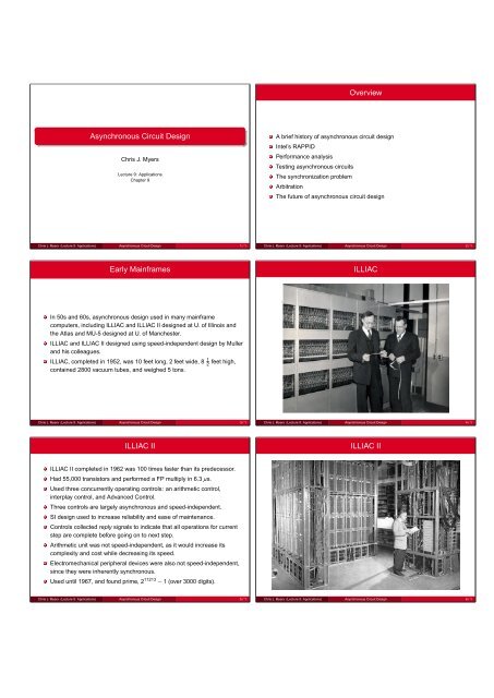
Early Mainframes<br />
In 50s and 60s, asynchronous design used in many mainframe<br />
computers, including ILLIAC and ILLIAC II designed at U. of Illinois and<br />
the Atlas and MU-5 designed at U. of Manchester.<br />
ILLIAC and ILLIAC II designed using speed-independent design by Muller<br />
and his colleagues.<br />
ILLIAC, completed in 1952, was 10 feet long, 2 feet wide, 8 1<br />
feet high,<br />
2<br />
contained 2800 vacuum tubes, and weighed 5 tons.<br />
Chris J. <strong>Myers</strong> (<strong>Lecture</strong> 9: Applications) Asynchronous Circuit Design 3 / 1<br />
ILLIAC II<br />
ILLIAC II completed in 1962 was 100 times faster than its predecessor.<br />
Had 55,000 transistors and performed a FP multiply in 6.3 µs.<br />
Used three concurrently operating controls: an arithmetic control,<br />
interplay control, and Advanced Control.<br />
Three controls are largely asynchronous and speed-independent.<br />
SI design used to increase reliability and ease of maintenance.<br />
Controls collected reply signals to indicate that all operations for current<br />
step are complete before going on to next step.<br />
Arithmetic unit was not speed-independent, as it would increase its<br />
complexity and cost while decreasing its speed.<br />
Electromechanical peripheral devices were also not speed-independent,<br />
since they were inherently synchronous.<br />
Used until 1967, and found prime, 2 11213 − 1 (over 3000 digits).<br />
Chris J. <strong>Myers</strong> (<strong>Lecture</strong> 9: Applications) Asynchronous Circuit Design 5 / 1<br />
Overview<br />
A brief history of asynchronous circuit design<br />
Intel’s RAPPID<br />
Performance analysis<br />
Testing asynchronous circuits<br />
The synchronization problem<br />
Arbitration<br />
The future of asynchronous circuit design<br />
Chris J. <strong>Myers</strong> (<strong>Lecture</strong> 9: Applications) Asynchronous Circuit Design 2 / 1<br />
ILLIAC<br />
Chris J. <strong>Myers</strong> (<strong>Lecture</strong> 9: Applications) Asynchronous Circuit Design 4 / 1<br />
ILLIAC II<br />
Chris J. <strong>Myers</strong> (<strong>Lecture</strong> 9: Applications) Asynchronous Circuit Design 6 / 1
ILLIAC II Control Panel<br />
Chris J. <strong>Myers</strong> (<strong>Lecture</strong> 9: Applications) Asynchronous Circuit Design 7 / 1<br />
Macromodules<br />
Chris J. <strong>Myers</strong> (<strong>Lecture</strong> 9: Applications) Asynchronous Circuit Design 9 / 1<br />
Macromodules<br />
Chris J. <strong>Myers</strong> (<strong>Lecture</strong> 9: Applications) Asynchronous Circuit Design 11 / 1<br />
Macromodules<br />
Developed in 60s and 70s at Washington University in St. Louis.<br />
Macromodules are “building blocks ... from which it is possible for the<br />
electronically-naive to construct arbitrarily large and complex computers<br />
that work.”<br />
Asynchronous to allow easy interconnection and to allow designers to<br />
worry only about logical and not electrical problems.<br />
Used to build macromodular computer systems by placing in a rack and<br />
interconnecting with wires.<br />
Wires carry data signals as well as a bundled data control signal.<br />
Wires also for control to sequence operations.<br />
Developed directly from a flowchart description of an algorithm.<br />
Many computing engines designed using macromodules.<br />
Chris J. <strong>Myers</strong> (<strong>Lecture</strong> 9: Applications) Asynchronous Circuit Design 8 / 1<br />
Macromodules<br />
Chris J. <strong>Myers</strong> (<strong>Lecture</strong> 9: Applications) Asynchronous Circuit Design 10 / 1<br />
Macromodules<br />
Chris J. <strong>Myers</strong> (<strong>Lecture</strong> 9: Applications) Asynchronous Circuit Design 12 / 1
Macromodules<br />
Chris J. <strong>Myers</strong> (<strong>Lecture</strong> 9: Applications) Asynchronous Circuit Design 13 / 1<br />
Caltech’s Asynchronous Microprocessors<br />
In 1989, designed first fully asynchronous microprocessor.<br />
Processor has a 16-bit datapath with 16- and 32-bit instructions.<br />
Has twelve 16-bit registers, 4 buses, an ALU, and 2 adders.<br />
Consists of 20,000 transistors, fabricated in 2 µm and 1.6 µm, and took<br />
five people only five months to design.<br />
2 µm version could perform 12 million ALU instructions per second, while<br />
the 1.6 µm version could perform 18 million.<br />
Chips operate with VDD from 0.35 to 7 V, and achieve almost double the<br />
performance when cooled in liquid nitrogen.<br />
Design is entirely quasi-delay insensitive (QDI).<br />
Design was derived from a high-level channel description using program<br />
transformations to introduce ideas like pipelining.<br />
Chris J. <strong>Myers</strong> (<strong>Lecture</strong> 9: Applications) Asynchronous Circuit Design 15 / 1<br />
Caltech’s Asynchronous Microprocessors (cont)<br />
Also designed first asynchronous GaAs microprocessor.<br />
This processor ran at 100 MIPS while consuming 2 W.<br />
Designed an asynchronous MIPS R3000 microprocessor.<br />
Design fabricated in 0.6 µm CMOS, and it uses 2 million transistors, of<br />
which 1.25 million are in its caches.<br />
Measured performance ranged from 60 MIPS and 220 mW at 1.5 V and<br />
25 ◦ C to 180 MIPS and 4 W at 3.3 V and 25 ◦ C.<br />
Running Dhrystone, the chip achieved about 185 MHz at 3.3 V.<br />
Chris J. <strong>Myers</strong> (<strong>Lecture</strong> 9: Applications) Asynchronous Circuit Design 17 / 1<br />
Data Driven Machines<br />
Rather than single PC, flow of data controls operation speed.<br />
In 70s, first operational dataflow computer, DDM-1, designed at U. of Utah<br />
and first commercial graphics system designed at Evans and Sutherland.<br />
In the 80s, Matsushita, Sanyo, Sharp, and Mitsubishi designed several<br />
data-driven processors.<br />
Most recently, a data-driven media processor (DDMP) has been designed<br />
at Sharp capable of 2400 million signal processing operations per second<br />
while consuming only 1.32 W.<br />
Videonics has utilized DDMP design in a high-speed video DSP.<br />
Asynchronous design of DDMP is cited to have simplified the board<br />
layout and reduced RF interference.<br />
Chris J. <strong>Myers</strong> (<strong>Lecture</strong> 9: Applications) Asynchronous Circuit Design 14 / 1<br />
Caltech’s Asynchronous Microprocessors<br />
Chris J. <strong>Myers</strong> (<strong>Lecture</strong> 9: Applications) Asynchronous Circuit Design 16 / 1<br />
AMULET<br />
AMULET1 completed in 1994 at U. of Manchester was the first<br />
asynchronous processor to be code-compatible with an existing<br />
synchronous processor, the ARM.<br />
Design style followed Sutherland’s two-phase micropipeline idea.<br />
Chip fabricated in a 1 µm and a 0.7 µm process.<br />
Performance was measured for the 1 µm part from 3.5 to 6 V completing<br />
between 15 and 25 thousand Dhrystones per second.<br />
MIPS/watt value was also measured to be from 175 down to 50.<br />
Chip operates correctly between −50 ◦ C and 120 ◦ C.<br />
Chris J. <strong>Myers</strong> (<strong>Lecture</strong> 9: Applications) Asynchronous Circuit Design 18 / 1
AMULET (cont)<br />
AMULET2e, targeting embedded systems, contained an AMULET2 core<br />
with a cache/RAM, a memory interface, and other control functions on<br />
chip.<br />
This design used four-phase bundled-data style.<br />
Design was fabricated in 0.5 µm CMOS, and its measured performance<br />
at 3.3 V was 74 kDhrystones, which is roughly equivalent to 42 MIPS and<br />
consumed 150 mW.<br />
The radio-frequency emission spectrum or EMC was shown to be<br />
significantly spread as compared with a clocked system.<br />
When processor enters “halt” mode, power is under 0.1 mW.<br />
AMULET3 has incorporated ARM thumb code and new architectural<br />
features to improve performance.<br />
Chris J. <strong>Myers</strong> (<strong>Lecture</strong> 9: Applications) Asynchronous Circuit Design 19 / 1<br />
SUN Pipelines<br />
In 1994, group at SUN suggested replicating synchronous architecture<br />
may not be the best for asynchronous design.<br />
Suggested a radically different architecture, the counterflow pipeline in<br />
which instructions are injected up the pipeline while contents of registers<br />
are injected down.<br />
When instruction meets register values, computes a result.<br />
Key to the performance of such a design are circuits to move data very<br />
quickly.<br />
This group has designed several very fast FIFO circuits.<br />
Test chips fabricated in 0.6 µm have a maximum throughput of between<br />
1.1 and 1.7 Giga data items per second.<br />
Chris J. <strong>Myers</strong> (<strong>Lecture</strong> 9: Applications) Asynchronous Circuit Design 21 / 1<br />
Designs at Philips <strong>Research</strong> Laboratories<br />
Most notable accomplishment is a fully asynchronous pager sold by<br />
Philips using standby circuits and 80C51 microcontroller.<br />
Major reason Philips uses asynchronous pager is it has a more evenly<br />
spread emission spectrum over the frequency range.<br />
Interference at clock frequency and harmonics requires digital circuitry in<br />
synchronous design to be shut off as message arrives.<br />
Spread-spectrum emission for asynchronous design allows digital<br />
circuitry to remain active as the message is received.<br />
Permits pager to be capable of being universal in that it can accept all<br />
three of the international pager standards.<br />
Chris J. <strong>Myers</strong> (<strong>Lecture</strong> 9: Applications) Asynchronous Circuit Design 23 / 1<br />
AMULET 3 Microprocessor<br />
Chris J. <strong>Myers</strong> (<strong>Lecture</strong> 9: Applications) Asynchronous Circuit Design 20 / 1<br />
Designs at Philips <strong>Research</strong> Laboratories<br />
Designed many asynchronous designs targeting low power.<br />
Developed design procedure from specification in TANGRAM to a chip,<br />
and applied to several commercially interesting designs.<br />
In 1994, produced an error corrector chip for a DCC player that<br />
consumed only 10 mW at 5 V, 1<br />
of synchronous counterpart.<br />
5<br />
Design also required only 20 percent more area.<br />
In 1997, designed standby circuits for a pager decoder which uses 4<br />
times less power while 40% larger than synchronous design.<br />
Results in a 37 percent decrease in power for entire pager.<br />
In 1998, this group designed an 80C51 microcontroller.<br />
Chip in 0.5 µm is 3 to 4 times more power efficient than synchronous<br />
counterpart, consuming only 9 mW at 4 MIPS.<br />
Chris J. <strong>Myers</strong> (<strong>Lecture</strong> 9: Applications) Asynchronous Circuit Design 22 / 1<br />
Epson’s Flexible 8-bit Asynchronous Microcontroller<br />
Chris J. <strong>Myers</strong> (<strong>Lecture</strong> 9: Applications) Asynchronous Circuit Design 24 / 1
Fulcrum’s 1GHz Processor using Asynchronous Circuits<br />
Chris J. <strong>Myers</strong> (<strong>Lecture</strong> 9: Applications) Asynchronous Circuit Design 25 / 1<br />
An Asynchronous Instruction-Length Decoder<br />
RAPPID (Revolving Asynchronous Pentium Processor Instruction<br />
Decoder) is a fully asynchronous instruction-length decoder for the<br />
complete PentiumII 32-bit MMX instruction set.<br />
RAPPID project conducted at Intel between 1995 and 1999.<br />
Achieved 3 fold improvement in speed and 2 fold improvement in power<br />
compared with existing synchronous design.<br />
Chris J. <strong>Myers</strong> (<strong>Lecture</strong> 9: Applications) Asynchronous Circuit Design 27 / 1<br />
100%<br />
80%<br />
60%<br />
100%<br />
80%<br />
60%<br />
40%<br />
20%<br />
0%<br />
RAPPID Data<br />
Instruction Length Statistics<br />
40%<br />
33.2%<br />
14.5% 24.4%<br />
20%<br />
0%<br />
9.8% 6.7% 8.1%<br />
2.8% 0.4% 0.0% 0.1% 0.0%<br />
Opcode Type Statistics<br />
Instruction Type<br />
Frequency<br />
Cummulative<br />
1 2 3 4 5 6 7 8 9 10 11<br />
Frequency<br />
Cummulative<br />
Chris J. <strong>Myers</strong> (<strong>Lecture</strong> 9: Applications) Asynchronous Circuit Design 29 / 1<br />
Cornel’s Asynchronous FPGAs (Achronix)<br />
Chris J. <strong>Myers</strong> (<strong>Lecture</strong> 9: Applications) Asynchronous Circuit Design 26 / 1<br />
x86 Instruction-Length Decoding<br />
Each instruction can be from 1 to 15 bytes long.<br />
To allow concurrent execution of instructions, necessary to rapidly<br />
determine positions of each instruction in a cache line.<br />
It was the critical bottleneck in this architecture.<br />
A partial list of rules to determine instruction length:<br />
Opcode can be 1 or 2 bytes.<br />
Opcode determines presence of the ModR/M byte.<br />
ModR/M determines presence of the SIB byte.<br />
ModR/M and SIB set length of displacement field.<br />
Opcode determines length of immediate field.<br />
Instructions may be preceded by as many as 15 prefix bytes.<br />
A prefix may change the length of an instruction.<br />
The maximum instruction length is 15 bytes.<br />
Chris J. <strong>Myers</strong> (<strong>Lecture</strong> 9: Applications) Asynchronous Circuit Design 28 / 1<br />
Byte Unit (BU)<br />
Row 0<br />
Row 1<br />
Row 2<br />
Row 3<br />
RAPPID Microarchitecture<br />
Input FIFO (IF)<br />
Decode and Steer Unit (DU)<br />
Column 0 1 2 3 4 5 6 7 8 9 10 11 12 13 14 15<br />
Byte<br />
Byte<br />
Latch<br />
Ctrl<br />
Length<br />
(BC) Decode<br />
(LD)<br />
Tag Unit (TU)<br />
Tag Unit (TU)<br />
Tag Unit (TU)<br />
Tag Unit (TU)<br />
Steering Switch (SS)<br />
Steering Switch (SS)<br />
Steering Switch (SS)<br />
Steering Switch (SS)<br />
Output Buffer<br />
Output Buffer<br />
Output Buffer<br />
Output Buffer<br />
Chris J. <strong>Myers</strong> (<strong>Lecture</strong> 9: Applications) Asynchronous Circuit Design 30 / 1
A<br />
B<br />
C<br />
Balanced Versus Unbalanced Logic<br />
Chris J. <strong>Myers</strong> (<strong>Lecture</strong> 9: Applications) Asynchronous Circuit Design 31 / 1<br />
B<br />
C<br />
A<br />
RAPPID Test Results<br />
Test chip fabricated in May 1998 using a 0.25 µm process.<br />
Capable of decoding and steering instructions at a rate of 2.5 to 4.5<br />
instructions per ns.<br />
Fastest synchronous 3-issue product in same fabrication process clocked<br />
at 400 MHz is capable of only 1.2 instructions per ns.<br />
Chip operated correctly between 1.0 and 2.5 V while synchronous design<br />
could only tolerate about 1.9 to 2.1 V.<br />
Consumes only 1<br />
of energy of clocked design.<br />
2<br />
Found to achieve these gains with only a 22 percent area penalty.<br />
Chris J. <strong>Myers</strong> (<strong>Lecture</strong> 9: Applications) Asynchronous Circuit Design 33 / 1<br />
Wine Shop Example: Timed Circuit<br />
CSC0<br />
ack_wine<br />
req_wine<br />
ack_patron<br />
req_patron<br />
ack_wine<br />
req_patron<br />
ack_patron<br />
C<br />
C<br />
ack_wine<br />
CSC0<br />
req_patron<br />
Chris J. <strong>Myers</strong> (<strong>Lecture</strong> 9: Applications) Asynchronous Circuit Design 35 / 1<br />
InstRdy<br />
SSRdy<br />
Tagln 1<br />
Tagln 2<br />
. . .<br />
Tagln 7<br />
Tag Unit Circuit<br />
Length 1<br />
Length 2<br />
TagArrived<br />
Length 7<br />
. . .<br />
. . .<br />
TagOut 1<br />
TagOut 2<br />
TagOut 7<br />
Chris J. <strong>Myers</strong> (<strong>Lecture</strong> 9: Applications) Asynchronous Circuit Design 32 / 1<br />
Performance Analysis<br />
For asynchronous design, cannot simply find critical path delay or count<br />
number of clock cycles per operation.<br />
Worst-case analysis may be quite pessimistic, as goal is to achieve high<br />
rates of performance on average.<br />
Must take a probabilistic approach to performance analysis.<br />
In TEL structure, it is necessary to extend model to include a distribution<br />
function for each delay.<br />
Simple approach is assume delay is uniform in its range.<br />
Another possibility is to use a truncated Gaussian.<br />
Most direct approach to determine performance analysis is a Monte Carlo<br />
simulation.<br />
Chris J. <strong>Myers</strong> (<strong>Lecture</strong> 9: Applications) Asynchronous Circuit Design 34 / 1<br />
Timing Assumptions<br />
Assumption Delay<br />
Winery delays 2 to 3 minutes<br />
Patron responds 5 to ∞ minutes<br />
Patron resets 2 to 3 minutes<br />
Inverter delay 0 to 6 seconds<br />
AND gate delay 6 to 12 seconds<br />
OR gate delay 6 to 12 seconds<br />
C-element delay 12 to 18 seconds<br />
Synchronous worst-case cycle time is 18.3 minutes<br />
Asynchronous average-case cycle time is 14.2 minutes<br />
Chris J. <strong>Myers</strong> (<strong>Lecture</strong> 9: Applications) Asynchronous Circuit Design 36 / 1
Testing Asynchronous Circuits (Bad News)<br />
Once chip fabricated, must test it to determine presence of manufacturing<br />
defects, or faults, before delivering to consumer.<br />
In asynchronous circuits, there is no global clock which can be used to<br />
single step the design through a sequence of steps.<br />
Asynchronous circuits have more state holding elements, which<br />
increases overhead to apply and examine test vectors.<br />
Huffman circuits use redundant circuitry to remove hazards which tends<br />
to hide some faults, making them untestable.<br />
Asynchronous circuits may fail due to glitches caused by delay faults,<br />
which are difficult to detect.<br />
Chris J. <strong>Myers</strong> (<strong>Lecture</strong> 9: Applications) Asynchronous Circuit Design 37 / 1<br />
Fault Locations<br />
Chris J. <strong>Myers</strong> (<strong>Lecture</strong> 9: Applications) Asynchronous Circuit Design 39 / 1<br />
req_wine<br />
ack_wine<br />
Testing Example 2<br />
r2<br />
r1<br />
x<br />
C<br />
x<br />
a2<br />
a1<br />
Consider r1 stuck-at-0<br />
req_wine+, x+, req_patron+<br />
req_patron<br />
ack_patron<br />
Chris J. <strong>Myers</strong> (<strong>Lecture</strong> 9: Applications) Asynchronous Circuit Design 41 / 1<br />
Testing Asynchronous Circuits (Good News)<br />
Since many asynchronous styles use handshakes, for many faults, a<br />
defective circuit simply halts.<br />
In the stuck-at fault model, a defect is assumed to cause a wire to<br />
become permanently stuck-at-0 or stuck-at-1.<br />
If acknowledge wire is stuck-at-0, the request is never acknowledged,<br />
causing the circuit to stop and wait forever.<br />
Easy to detect with a timeout.<br />
The circuit is said to be self-checking.<br />
Delay-insensitive circuits halt in the presence of any stuck-at fault on any<br />
wire in the design.<br />
Muller circuits halt for any output stuck-at fault.<br />
Chris J. <strong>Myers</strong> (<strong>Lecture</strong> 9: Applications) Asynchronous Circuit Design 38 / 1<br />
req_wine1<br />
ack_wine1<br />
ack_wine2<br />
Testing Example 1<br />
C<br />
req_wine2 C<br />
req_patron1<br />
ack_patron1<br />
ack_patron2<br />
req_patron2<br />
Chris J. <strong>Myers</strong> (<strong>Lecture</strong> 9: Applications) Asynchronous Circuit Design 40 / 1<br />
Other Testing Issues<br />
In the isochronic fork fault model, faults can be detected on all branches<br />
of a nonisochronic fault by the circuit halting, but only on the input to forks<br />
that are isochronic.<br />
More complex delay fault and bridging fault models have been<br />
successfully adapted to asynchronous circuits.<br />
Once have fault model, next step is to add circuitry to apply and analyze<br />
test vectors, such as scan paths.<br />
Must also generate sufficient set of test vectors to guarantee a high<br />
degree of coverage of all possible faults in our model.<br />
While traditional synchronous test methods don’t work off the shelf, many<br />
popular methods adapted to asynchronous problem.<br />
Chris J. <strong>Myers</strong> (<strong>Lecture</strong> 9: Applications) Asynchronous Circuit Design 42 / 1
The Synchronization Problem<br />
It is difficult to reliably communicate between asynchronous and<br />
synchronous modules without substantial latency penalties.<br />
Synchronous circuit sampling asynchronous signal changing too close to<br />
the clock edge may end up in a metastable state.<br />
If this state persists so long that something bad happens, this is called a<br />
synchronization failure.<br />
Chris J. <strong>Myers</strong> (<strong>Lecture</strong> 9: Applications) Asynchronous Circuit Design 43 / 1<br />
Flip-Flop Response Time<br />
t<br />
0<br />
t t<br />
su<br />
r<br />
Chris J. <strong>Myers</strong> (<strong>Lecture</strong> 9: Applications) Asynchronous Circuit Design 45 / 1<br />
Probability of Synchronization Failure (cont)<br />
If tb − tpd ≥ 5τ, Equation ?? can be simplified as follows:<br />
P(tr > tb) ≈ th − tsu<br />
T<br />
h<br />
· e−(tb−tpd)/τ<br />
1 − k<br />
By combining constants, Equation ?? can be changed to<br />
P(tr > tb) ≈ T0<br />
· e−tb/τ<br />
T<br />
T0 and τ scale linearly with feature size.<br />
Equation ?? has been verified experimentally and found to be a good<br />
estimate as long as tb is not too close to tpd.<br />
There is no finite value of tb such that P(tr > tb) = 0.<br />
Chris J. <strong>Myers</strong> (<strong>Lecture</strong> 9: Applications) Asynchronous Circuit Design 47 / 1<br />
t<br />
pd<br />
t<br />
d<br />
(5)<br />
(6)<br />
Asynchronous<br />
Input<br />
Voltage<br />
D<br />
CLK<br />
Metastability<br />
D<br />
CLK<br />
Q<br />
Q<br />
Q’<br />
Synchronized<br />
Input<br />
Time<br />
Chris J. <strong>Myers</strong> (<strong>Lecture</strong> 9: Applications) Asynchronous Circuit Design 44 / 1<br />
Probability of Synchronization Failure<br />
Data arrive at time uniformly distributed within clock cycle, T .<br />
P(td ∈ [tsu,th]) = th − tsu<br />
T<br />
Assume flip-flop is given bounded amount of time, tb:<br />
P(tr > tb | td ∈ [tsu,th]) =<br />
1<br />
k +(1 − k)e (tb−tpd)/τ<br />
k is a positive fraction less than 1 and τ is a time constant with values on<br />
the order of a few picoseconds for modern technologies.<br />
Combine Equations ?? and ?? using Bayes rule:<br />
P(tr > tb) = P(td ∈ [tsu,th]) · P(tr > tb | td ∈ [tsu,th]) (3)<br />
= th − tsu<br />
1<br />
·<br />
T k +(1 − k)e (tb−tpd)/τ<br />
(4)<br />
Chris J. <strong>Myers</strong> (<strong>Lecture</strong> 9: Applications) Asynchronous Circuit Design 46 / 1<br />
Synchronization Error<br />
A synchronization error occurs when tr is greater than time available to<br />
respond, ta.<br />
A synchronization failure occurs when there is an inconsistency caused<br />
by the error.<br />
Expected number of errors is<br />
(1)<br />
(2)<br />
Ee(ta) = P(tr > ta) · λ · t (7)<br />
where λ is the average rate of change of the signal being sampled and t<br />
is the time over which the errors are counted.<br />
Chris J. <strong>Myers</strong> (<strong>Lecture</strong> 9: Applications) Asynchronous Circuit Design 48 / 1
Mean Time Between Failure<br />
If we set Ee(ta) to 1, change t to MTBF (mean time between failure),<br />
substitute Equation ?? for P(tr > ta), and rearrange Equation ??, we get<br />
MTBF =<br />
T · eta/τ<br />
T0 · λ<br />
This equation increases rapidly as ta is increased.<br />
Though no absolute bound in which no failure can ever occur, there does<br />
exist an engineering bound.<br />
Chris J. <strong>Myers</strong> (<strong>Lecture</strong> 9: Applications) Asynchronous Circuit Design 49 / 1<br />
Reducing the Probability of Failure<br />
If n extra latches are added in series with an asynchronous input, the new<br />
value of ta is given by<br />
(8)<br />
t ′ a = ta + n(T − tpd) (9)<br />
where T is the clock period and tpd is the propagation delay through the<br />
added flip-flops.<br />
IMPORTANT: INCORRECT IN THE BOOK.<br />
Cost is extra n cycles of delay when communicating data from an<br />
asynchronous module to a synchronous module.<br />
This scheme only minimizes probability and does not eliminate the<br />
possibility of synchronization failure.<br />
Chris J. <strong>Myers</strong> (<strong>Lecture</strong> 9: Applications) Asynchronous Circuit Design 51 / 1<br />
ACK<br />
REQ<br />
Stoppable Ring Oscillator Clock with ME<br />
R1<br />
ME<br />
A1<br />
R2 A2<br />
Odd number of inverters<br />
CLK<br />
Chris J. <strong>Myers</strong> (<strong>Lecture</strong> 9: Applications) Asynchronous Circuit Design 53 / 1<br />
Asynchronous<br />
Input<br />
CLK<br />
Double Latch Solution<br />
D Q<br />
D Q<br />
Q’<br />
Q’<br />
Synchronized<br />
Input<br />
Chris J. <strong>Myers</strong> (<strong>Lecture</strong> 9: Applications) Asynchronous Circuit Design 50 / 1<br />
RUN<br />
Stoppable Ring Oscillator Clock<br />
Odd number of inverters<br />
CLK<br />
Chris J. <strong>Myers</strong> (<strong>Lecture</strong> 9: Applications) Asynchronous Circuit Design 52 / 1<br />
R1<br />
R2<br />
Circuit for Mutual Exclusion<br />
V1<br />
V2<br />
T1<br />
T2<br />
Chris J. <strong>Myers</strong> (<strong>Lecture</strong> 9: Applications) Asynchronous Circuit Design 54 / 1<br />
A2<br />
A1
Basic Module of a GALS Architecture<br />
Data in<br />
Synchronous<br />
Module<br />
Data out<br />
ReqIn<br />
AckIn<br />
Local<br />
Clock<br />
Generator<br />
CLK<br />
ReqOut<br />
AckOut<br />
Chris J. <strong>Myers</strong> (<strong>Lecture</strong> 9: Applications) Asynchronous Circuit Design 55 / 1<br />
Arbitration<br />
Arbitration necessary when two or more modules want mutually exclusive<br />
access to a shared resource.<br />
If modules are asynchronous, arbitration also cannot be guaranteed in a<br />
bounded amount of time.<br />
If all modules are asynchronous, it is possible to build an arbiter with zero<br />
probability of failure.<br />
Chris J. <strong>Myers</strong> (<strong>Lecture</strong> 9: Applications) Asynchronous Circuit Design 57 / 1<br />
R1<br />
A1<br />
R2<br />
A2<br />
R3<br />
A3<br />
R4<br />
A4<br />
Four-Way Arbiters<br />
R<br />
A<br />
R1<br />
A1<br />
R2<br />
A2<br />
Chris J. <strong>Myers</strong> (<strong>Lecture</strong> 9: Applications) Asynchronous Circuit Design 59 / 1<br />
R3<br />
A3<br />
R4<br />
A4<br />
R<br />
A<br />
Sync<br />
Module<br />
Interface<br />
Controller<br />
LAGS Architecture<br />
Reg. Reg. Reg. Reg.<br />
Async / Sync<br />
Async<br />
Async<br />
Module<br />
Sync<br />
Module<br />
Module<br />
REQ ACK REQ ACK<br />
Handshake<br />
Controller<br />
Stoppable<br />
Clock<br />
RUN<br />
Handshake<br />
Controller<br />
Chris J. <strong>Myers</strong> (<strong>Lecture</strong> 9: Applications) Asynchronous Circuit Design 56 / 1<br />
A1<br />
R1<br />
R2<br />
A2<br />
ME<br />
Circuit for Arbitration<br />
Chris J. <strong>Myers</strong> (<strong>Lecture</strong> 9: Applications) Asynchronous Circuit Design 58 / 1<br />
Future of Asynchronous Design<br />
Papers in 60s and 70s cite same advantages of asynchronous design<br />
used in papers today.<br />
C<br />
C<br />
CLK<br />
Synchronous design has been so simple to understand and use.<br />
Asynchronous revolution may be quite gradual.<br />
Even if it never happens asynchronous research has been useful.<br />
Hopefully when you reach industry, you will consider using asynchronous<br />
design!<br />
Chris J. <strong>Myers</strong> (<strong>Lecture</strong> 9: Applications) Asynchronous Circuit Design 60 / 1<br />
A3<br />
R3