Software Defined Radios for VHF Through SHF By Gerald ... - TAPR
Software Defined Radios for VHF Through SHF By Gerald ... - TAPR
Software Defined Radios for VHF Through SHF By Gerald ... - TAPR

You also want an ePaper? Increase the reach of your titles
YUMPU automatically turns print PDFs into web optimized ePapers that Google loves.
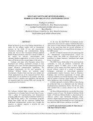
<strong>Software</strong> <strong>Defined</strong> <strong>Radios</strong> <strong>for</strong> <strong>VHF</strong> <strong>Through</strong> <strong>SHF</strong><br />
<strong>By</strong><br />
<strong>Gerald</strong> Youngblood, K5SDR (ex. AC5OG)<br />
FlexRadio Systems<br />
The FlexRadio Systems’ SDR-1000 is the first commercially available <strong>Software</strong> <strong>Defined</strong><br />
Radio (SDR) transceiver <strong>for</strong> the amateur radio market. The SDR-1000 began shipping in<br />
April of 2003 with GPL open source software, a first <strong>for</strong> a commercial transceiver. This<br />
has created a groundswell of support <strong>for</strong> the radio from contributors worldwide. This is<br />
evidenced by the constant improvement available through free software downloads on<br />
almost a weekly basis. These enhancements are well documented in the October 2005<br />
QST product review, “FlexRadio Systems SDR-1000 HF+<strong>VHF</strong> <strong>Software</strong> <strong>Defined</strong> Radio<br />
Redux.” The current SDR-1000 now boasts dynamic range per<strong>for</strong>mance that meets or<br />
exceeds that of radios costing ten times its cost.<br />
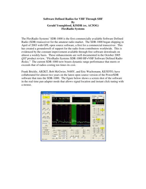
Frank Brickle, AB2KT, Bob McGwier, N4HY, and Eric Wachsmann, KE5DTO, have<br />
collaborated <strong>for</strong> almost two years on the latest open source version of the PowerSDR<br />
software that runs the SDR-1000. The figure below shows a screen shot of the software<br />
in the real time pan adapter mode that allows signal location and instant click tuning with<br />
a mouse.
The SDR-1000 Moves to <strong>VHF</strong> and Beyond<br />
While the SDR-1000 has been thought of as a HF radio, many prominent amateurs are<br />
moving to the SDR-1000 as their IF radio of choice <strong>for</strong> <strong>VHF</strong>, UHF and microwave. Key<br />
features that are available on the SDR-1000 <strong>for</strong> <strong>VHF</strong>+ enthusiasts are:<br />
• Real time click to tune pan adapter spotting<br />
• No ring filters to 25Hz<br />
• SDROM impulse noise removal<br />
• 10 or 20MHz LO reference input option<br />
• Extremely high dynamic range IF (99dB IMD DR3)<br />
• 2m DEMI IF option<br />
• Integrated transverter and antenna software control with UCB<br />
• 48KHz Bandwidth IF Record/Playback<br />
<strong>Through</strong> collaboration between Mike King, KM0T, Tony Parks, KB9YIG, Terry van<br />
Benschoten, W0VB, and FlexRadio Systems, a Universal Controller Board (UCB) has<br />
been developed and integrated with the SDR-1000 to allow transparent software control<br />
of up to 16 external transverters and/or antennas. In fact, there are also 16 possible<br />
combinations of those 16 devices that may be controlled under the software. It allows <strong>for</strong><br />
full control of band switching, sequencing, and PTT by simply changing the frequency on<br />
the PowerSDR console. <strong>By</strong> the time this paper is in print, the software will provide direct<br />
frequency readout in GHz with transverter-offset correction. That means that one could<br />
within seconds QSY from 144MHz to 24GHz with a single click, find the signal on the<br />
real time spectrum and click to tune on frequency.<br />
This paper will describe the integration and operation of the UCB with the SDR-1000 IF<br />
<strong>for</strong> microwave operation at the KM0T location. A special thanks goes to KM0T and<br />
W0VB <strong>for</strong> allowing FlexRadio to use their materials to show a real world user<br />
application of the SDR-1000.<br />
The UCB hardware was designed and has been produced by W9YIG. While the UCB is<br />
currently available only through W9YIG, FlexRadio Systems is considering its addition<br />
to the standard product line.<br />
The UCB is a single PCB with a 15-pin connection to the External Control (X2)<br />
connector on the back panel of the SDR-1000. The X2 connector provides PTT input and<br />
output as well as six spare open collector switched outputs. These six outputs can be set<br />
under software control <strong>for</strong> simple external control by band with no other external<br />
hardware. However, with the addition of the UCB, very sophisticated control options are<br />
available including separate antenna, transverter and PTT control. It even allows the<br />
choice of binary or BCD control of antenna switching relays as seen in the KM0T<br />
installation.<br />
The photo below shows the UCB on the right with an 8-position SMA coaxial relay on<br />
the left. The coax relay uses BCD encoding <strong>for</strong> control so the UCB must provide the
necessary codes to select each band. Headers are provided <strong>for</strong> the normally open and<br />
normally closed contacts on each of the 16 relays. LEDs provide status indication <strong>for</strong><br />
each relay as well as other control and data lines. The board is powered by an external<br />
__V supply. A 15-pin loop through connector allows dedicated control signals from the<br />
X2 connector to be passed through the UCB.<br />
KM0T has designed his new station <strong>for</strong> operation on all microwave bands from 50MHz<br />
to 47GHz, with room to grow. He decided to integrate the UCB, 8-position coax relay,<br />
and all PTT connections in a single enclosure <strong>for</strong> a clean installation in the shack. The<br />
following two photos show the rear panel layout in progress. The coax relay is mounted<br />
on a bracket on the left with semi rigid coax connections to the panel mounted SMA<br />
connectors. A bank of 12 gold plated RCA connectors are mounted on the right hand<br />
side <strong>for</strong> PTT control outputs.
The photo above shows the completed controller module with all interface wiring<br />
installed. The single red and black wiring pair protruding from the grommet at the<br />
bottom center of the back panel is the DC power supply input. The final station<br />
installation may be seen in the following two photos. Note the neatness of the<br />
installation <strong>for</strong> coverage of all bands from 50MHz through 24GHz!
KM0T QTH<br />
Integration of the SDR-1000 with UCB in the station requires a careful planning. The<br />
key steps are as follows:<br />
1. Draw a wiring diagram of the station with all accessories to be controlled.<br />
Include all relays, PTT, power wiring, and other control logic required <strong>for</strong> the<br />
installation.<br />
2. Create a spreadsheet matrix <strong>for</strong> the control logic by band and map each band to a<br />
UCB control register address.<br />
3. Wire the station according to the schematic and control logic matrix.<br />
4. Program the PowerSDR software by band according the control logic matrix.<br />
5. Turn on the SDR-1000 and have fun.<br />
The schematic on the next page provides the final wiring configuration at the KM0T<br />
location. Note the UCB at the bottom left of the drawing shows each relay and how it is<br />
connected to the other major components. The BCD control signals <strong>for</strong> the 8-position<br />
coax relay are clearly indicated. The SDR-1000 is used as a 28MHz IF <strong>for</strong> all bands.<br />
Note the two relays to the right and above the 28-144MHz transverter provide <strong>for</strong> low<br />
band selection. The SDR-1000 allows a sequenced PTT output with a user<br />
programmable delay time in milliseconds.
KM0T STATION WIRING DIAGRAM
KM0T CONTROL MATRIX TABLE
Note how the UCB registers control multiple functions on each address. Application of<br />
the control bits is as follows:<br />
1. B0-B2 – BCD control of 8-position coax relay<br />
2. B3 – Low/High band selection relay<br />
3. B4-B7 – Binary control of low band PTT relays<br />
4. B8-B15 – Binary control <strong>for</strong> high band PTT relays<br />
Once the hardware is installed it is time to program the PowerSDR software to properly<br />
control the station. At the time of writing, the UCB Configuration and Setup <strong>for</strong>m is<br />
shown below. Note how the previous spreadsheet data is directly programmed into the<br />
<strong>for</strong>m’s matrix. Testing of each band is accomplished by clicking on the respective radio<br />
button on the left.
Now that setup is done, the moment of truth is to make contacts on all the microwave<br />
bands in just minutes with N0DQS. The presentation will include a video recording of<br />
the sequence of contacts from 902MHz through 24GHZ!<br />
Coming Soon to a SDR-1000 Near You<br />
PowerSDR software plans include instant band switching and direct frequency readout.<br />
Using the <strong>VHF</strong>+ button on the front console the band buttons will convert to <strong>VHF</strong>+<br />
bands three band-stacking registers per band. The setup <strong>for</strong>m will allow programming of<br />
offsets <strong>for</strong> each transverter so that direct frequency readout is possible that corrects <strong>for</strong><br />
oscillator-offset error in each transverter. With the SDR-1000, UCB, and PowerSDR<br />
software, QSY to any of the <strong>VHF</strong>+ bands becomes as easy as switching HF bands. Now<br />
“DC to light” operation is possible from a single operating position.