Installation Instructions - Omix-ADA
Installation Instructions - Omix-ADA
Installation Instructions - Omix-ADA

Create successful ePaper yourself
Turn your PDF publications into a flip-book with our unique Google optimized e-Paper software.
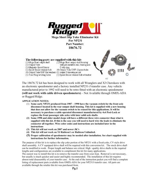
Mega Short Slip Yoke Eliminator Kit<br />
For NP231<br />
Part Number:<br />
18676.72<br />
The 18676.72 kit has been designed to work with all Wranglers and XJ Cherokees with<br />
an electronic speedometer and a factory installed NP231-J transfer case. Any vehicle<br />
manufactured prior to 1992 will need to be retro fitted with an electronic speedometer<br />
(will not work with cable driven speedometers) – Not Available through OMIX-<strong>ADA</strong><br />
or Rugged Ridge.<br />
APPLICATION NOTES:<br />
(1) Some early NP231 produced from 1987 – 1990 have the vacuum switch for the front axle<br />
disconnect located in the rear output shaft housing. This kit is supplied with a new housing<br />
that does not allow for the vacuum switch to be reused for this applications. It will be<br />
necessary to purchase a cable operated disconnect manufactured by 4x4 Posi-Lock or<br />
replace the front passenger side axles with later solid axle shafts.<br />
(2) Some 1998 and older model Jeeps will have a different three wire connecter than what is<br />
supplied with this kit. If this is the case you will need to hard wire the leads to eliminate the<br />
connector all together. Wire color codes and instructions are included later in the<br />
instructions<br />
(3) This kit will not work on 2007 and newer JK’s<br />
(4) This kit will not work on TJ Rubicon’s or Rubicon Unlimited.<br />
(5) Proper calibration of speedometer may be needed after installation. See chart supplied with<br />
instructions for further information.<br />
The purpose of this kit is to replace the slip yoke portion of the NP231 with a fixed-yoke, CV-style drive<br />
shaft assembly. A CV equipped drive shaft will be required with this conversion kit. The stock drive shaft<br />
can be modified to work. Proper length and balance are critical. High –quality drive shafts in the required<br />
lengths and configurations are available to compliment this kit for many applications.<br />
The easiest way to install this kit is to remove the transfer case from your Jeep. Removal is not necessary,<br />
but usually is much quicker and easier and highly recommended. The installation of this kit requires<br />
almost total disassembly of your transfer case. At the end of the instruction packet you will find a complete<br />
listing of replacement parts available from OMIX-<strong>ADA</strong> for your NP231J transfer case. All parts are<br />
available through the retailer this kit was purchased from.<br />
Pg.1
<strong>Installation</strong> <strong>Instructions</strong>: 18676.72<br />
Several suggestions that may help:<br />
(1) The installation of this kit requires you to nearly disassemble the entire case. If<br />
you need to rebuild, or feel like you have additional worn parts, now would be the<br />
time to do so.<br />
(2) Obtain a service manual for your Jeep. This will provide illustrations and<br />
information regarding parts identification, torque values, and other important data.<br />
(3) Use photos, and notes; mark and label all parts for future reference.<br />
(4) Keep all bolts, nuts, washers, ect. separated into groups as you remove them.<br />
Place inside zip-lock bags and mark location removed from.<br />
(5) Make sure you have all the required tools, pre-lubricants, RTV sealant (OEM part<br />
number : 82300234), thread-locker, and a clean work area.<br />
(6) Make sure you have the time needed to perform this conversion without being<br />
rushed.<br />
STEP 1: Remove the transfer case from the Jeep. Drive shafts, speedometer drive unit,<br />
linkages, etc must be removed. The case must be separated from the transmission. Refer<br />
to your service manual for details.<br />
STEP 2: Remove front yoke nut and yoke. Shift the range lever into the 4 Low position.<br />
Remove the selector lever. All of these parts will be re-used.<br />
STEP 3: Remove the output shaft boot and dust shield. Some newer models may have a<br />
harmonic balancer. There may be other slight model variations. Refer to your service<br />
manual for details.<br />
STEP 4: Remove the spacer and snap ring. Remove the seal, inner snap ring (on the<br />
shaft), and the bearing retainer ring. Remove the output housing bolts and then remove<br />
the existing output assembly.<br />
Photo 1. NP231 after completion of the first four steps of the disassembly process. The<br />
oil pump pickup tube may need to be removed before the case halves can be split<br />
Pg.2
<strong>Installation</strong> <strong>Instructions</strong>: 18676.72<br />
STEP 5: Mark the locations of the rear case half bolts before removing them. Start the<br />
case separation process by using the cast-in pry bar location slots only. Prying anywhere<br />
else on the case halves may create an uneven surface that will not seal properly when<br />
reassembled. Carefully begin to pry the case halves apart. Some models will be able to<br />
remove the pickup tube and pump assembly with the rear case.<br />
NOTE: Inspect the pickup tube o-ring and the front shaft seal in the pump. Do not take<br />
the pump apart it is not serviceable.<br />
Photo 2. NP231 with the rear case and oil pump assembly removed. Clean and inspect<br />
all parts.<br />
STEP 6: Remove the front output shaft. Remove the chain from the main shaft. Clean<br />
and inspect the chain and gears.<br />
STEP 7: Remove the main shaft from the front case. Make note of the locations of the<br />
snap rings, mode hub and sprocket. All of these items will be positioned on the new<br />
shaft.<br />
NOTE: On many earlier models the sprocket used two<br />
caged needle bearings. These bearings will need to be<br />
removed in order for the sprocket to be installed on the<br />
new shaft. DISCARD cage bearings – no longer needed.<br />
Pg.3
<strong>Installation</strong> <strong>Instructions</strong>: 18676.72<br />
STEP 8: Be sure all parts are clean and serviceable. Prelube all parts before installation.<br />
Place the mode hub, sprocket, and retaining ring into position on the new shaft. NOTE:<br />
you may need to remove cage bearings from the drive sprocket on early NP231J.<br />
See diagram above. These bearings will not be needed – Discard.<br />
Photo 3. Mode hub, drive sprocket, and retaining ring positioned on the new main shaft.<br />
These parts are now ready to re-install. AGAIN !! (Early model 231’s might require<br />
the removal of the needle bearing cage from the drive sprocket before it can be<br />
installed. Discard needle bearing cages as they are no longer needed.)<br />
STEP 9: With the case disassembled inspect the mode fork shift rod (see image above).<br />
If the shift rod measures 10.2” than you will need to cut it down to a length of 9.380”.<br />
This has been found to be a common problem for 1988- 1989 YJ models. You will need<br />
to cut the shift rod at the end located on the back side of the transfer case (Yoke side).<br />
Make sure that after cutting all burs and ruff edges have been cleaned.<br />
Pg.4
<strong>Installation</strong> <strong>Instructions</strong>: 18676.72<br />
STEP 10: Lubricate the shaft assembly, chain, and shaft bearing surfaces. Install the<br />
main shaft assembly into the front case half planetary assembly. Place the front output<br />
shaft on the chain and work them into position with the main shaft and case. Once they<br />
are properly located replace the mode spring onto the shift rail.<br />
Photo 4. NP231 after completion of the first 10 steps. The rear case half is now ready to<br />
be installed.<br />
STEP 11: Clean both halves of the transfer case and remove any excess transmission<br />
fluid. It is important to not have any oil, grease, or ATF on the case mating surfaces<br />
when ATV silicone is used.<br />
STEP 12: Be sure the oil pump and pick up tube are properly located. Use RTV sealant<br />
( OEM P/N: 82300234) on the case halves. A good seal will prevent oil leaks. Slide the<br />
rear case half on and into position. Do not force the case together. Rotate the oil pump<br />
as needed to engage the splines. The mode fork shift rail needs to extend through the<br />
rear case half. Before installing the case bolts start one to hold the back half of the case<br />
in place and inspect to see if oil pump pickup tube is still in the correct location. If yes<br />
than install all the bolts in their proper locations and torque to 25-30 ft/lbs. Reinstall the<br />
selector lever.<br />
STEP 13: With the back half of the case tightened to the proper torque spec slide the<br />
speed sensor tone ring onto the main shaft (see image above). Tone ring should have the<br />
tall edge facing towards the back of the transfer case and the flanged side (short edge)<br />
should be facing the yoke (threaded) side of the main shaft.<br />
STEP 14: Clean the mating surface of the transfer case and the Mega Short output<br />
housing before proceeding. Pre-lube bearing and apply ATV to the output housing.<br />
NOTE: the housing should already have the bearing, seal and bearing C-clip ring<br />
installed by the factory. With all components in place install the Mega Short output<br />
housing reusing the OE bolts used to hold the factory output housing in place.<br />
Pg.5
<strong>Installation</strong> <strong>Instructions</strong>: 18676.72<br />
WARNING!!! If you experience difficulty installing the Mega Short output housing<br />
check to make sure you have properly installed the speed sensor tone ring in<br />
accordance with step # 13. The outer edge of the sensor is sloped and must match<br />
the angle of the speed sensor pickup when installed.<br />
STEP 15: Pre-lube the surfaces on the yokes where both the inner and outer seals will be.<br />
Slide the yokes on and tighten the retaining nuts to 170-180 ft/lbs.<br />
STEP 16: Install the Magnetic speed sensor into the Mega Short output housing. It is<br />
important to use a small amount of oil or ATF on the o-ring to insure easy installation<br />
and avoid splitting and breaking the o-ring. Hand tighten the sensor retainer bolt and<br />
washer. Torque to 7ft-lbs. DO NOT OVER TIGHTEN, damage may occur to sensor.<br />
STEP 17: Reinstall the transfer case into the vehicle. Be sure to reinstall the drain plug<br />
and fill it to the recommended level with the proper fluid. Reconnect all the required<br />
items like the front drive shaft, shift linkages, new 3-wire connector into factory harness.<br />
NOTE: 4 new 5/15” – 12 point bolts have been supplied to aid with the installation of the<br />
rear drive shaft to output yoke. Do to clearance a standard ½” wrench can not be used for<br />
this application.<br />
IMPORTANT INFORMATION!<br />
STEP 18: Proper rear CV-drive shaft measurements.<br />
Take measurements for the required CV-equipped rear drive shaft. You will need to<br />
replace your rear drive shaft with a new unit as the original slip yoke shaft can no longer<br />
be used. Measure a straight line from the transfer case rear output yoke to the rear pinion<br />
yoke to determine the required length of your new driveshaft. If a new drive shaft is<br />
needed OMIX- <strong>ADA</strong> (Rugged Ridge) does have shafts that can be purchased depending<br />
on your vehicles overall lift. These shafts are for general use and you may want to have a<br />
custom unit made if the sizes offered will not work for your application.<br />
Pg. 6
<strong>Installation</strong> <strong>Instructions</strong>: 18676.72<br />
Drive shaft modifications to Original Unit.<br />
The modification of your drive shaft should be performed by a local driveline repair shop<br />
that is capable of balancing your finished assembly.<br />
Note: Use a C.V. joint & a long slip spline style shaft assembly to avoid problems<br />
with lifted vehicles.<br />
If you wish to have a custom driveshaft fabricated you will need to get your new<br />
driveshaft measurement length. Use the measurement procedures listed in step #18.<br />
Note: for proper C.V. type drive shaft operations, the rear differential<br />
yoke should be pointing at the transfer case output yoke. This should be<br />
checked under normal driving conditions and load<br />
STEP 19: - Speedometer Calibration Data<br />
Proper calibration of the speedometer will greatly depend on what changes have been<br />
made to the axle gear ratio and tire size. There are some combinations that will not<br />
require calibration changes (refer to the chart below) and are shown in the color gray.<br />
The other data reflects what your speedometer percentage of error will be if the<br />
speedometer is not recalibrated. If your vehicle requires recalibration a converter box can<br />
be purchase. (Not Available from <strong>Omix</strong>-Ada – Rugged Ridge).<br />
Pg.7
<strong>Installation</strong> <strong>Instructions</strong>: 18676.72<br />
The following information will be used if working with a 1998 and older NP231J’s equipped with<br />
different connector design than what has been supplied in this kit.<br />
For the installer to use the Rugged Ridge 18676.72 MSSYE Kit in vehicles older than 1999 it may be<br />
necessary to cut both connector leads to hard wire into the vehicles wire harness.<br />
Wiring diagram shows the correct color code needed to splice wires.<br />
Cut wires located directly after the female and connector located on the chasse of the<br />
vehicle and on the new 18676.71 male speed sensor supplied in the kit. This will leave<br />
you with 3 wires for both to reconnect to the new speed sensor. After trimming the plastic<br />
protective cover from both the chasses wires and the new sensor slide heat shrink wraps<br />
over each wire (cut to proper length). NOTE: the heat shrink wrap is not supplied in<br />
this kit. You will need to source this from an auto parts or electronic retailer. The<br />
Orange wire is the 5V power supply, the Black wire is the sensor ground wire, and the<br />
White or Brown wire is the sensor speed signal wire. The supplied connectors should<br />
match factory wire colors to help speed installation. With all wires properly connected<br />
(heat solder only) slide shrink tube over soldered wires and heat to seal. For added<br />
protection the use of 3M electrical tape is recommended over the shrink wrapped wires.<br />
If desired the use of connectors can be used to allow the disconnection of the sensor<br />
without removal. It is recommended that quality connectors be used to avoid corrosion at<br />
terminal connectors.<br />
Pg. 8
Parts Breakdown: 18676.72<br />
The following parts are supplied with this kit:<br />
(1) Mega Short output shaft (1) Mega Short output shaft housing<br />
(1) Output Yoke with pre-installed seal, bearing and<br />
(1) Magnetic Speed Sensor C-clip ring.<br />
(1) Speed Sensor retainer bolt (4) Output Yoke UNF 12 point bolts<br />
(4) Output Yoke UNF flat washers (1) output Yoke retainer nut<br />
(1) Tone Ring w/oiling holes (1) Speed Sensor retainer bolt w/washer<br />
Pg. 9
NP231J Parts List (OMIX-<strong>ADA</strong>)<br />
Pg. 10
LIMITED 6 MONTH – or 6,000 MILE WARRANTY<br />
Applies to Rugged Ridge by <strong>Omix</strong>-ada Inc. Products<br />
Rugged Ridge Off Road (the Company) warrants to the original purchaser of this product that should the<br />
product or any part thereof, under normal use and conditions, be proven defective in material or<br />
workmanship within 6 months – or 6,000 miles (which ever comes first) from the date of original purchase,<br />
such defect(s) will be repaired or replaced or credited at the Company’s sole option.<br />
To obtain repair or replacement within the terms of this Warranty, the product is to be delivered with proof of<br />
warranty coverage (e.g. Dated bill of sale), specification of defect(s) to the place of purchase or, with prior<br />
approval from the Company (Return Authorization Number is required), freight pre-paid to the Company<br />
address listed below.<br />
This warranty does not apply to any product or part thereof which, in the opinion of the Company, has<br />
suffered or been damaged through alteration, improper installation, mishandling, misuse, neglect, accident<br />
or by acts of nature. THE EXTENT OF THE COMPANY’S LIABILITY UNDER THIS WARRANTY IS<br />
LIMITED TO THE REPAIR OR REPLACEMENT PROVIDED ABOVE AND, IN NO EVENT, SHALL THE<br />
COMPANY’S LIABILITY EXCEED THE PURCHASE PRICE PAID BY PURCHASER FOR THE PRODUCT.<br />
This Warranty is in lieu of all express warranties or liabilities. ANY IMPLIED WARRANTIES, INCLUDING<br />
ANY IMPLIED WARRANTY OF MERHCHANTABILITY, SHALL BE LIMITED TO THE DURATION OF THIS<br />
WRITTEN WARRANTY. ANY ACTION FOR BREACH OF ANY WARRANTY HEREUNDER INCLUDING<br />
ANY IMPLIED WARRANTY OF MERCHANTABILITY MUST BE BROUGHT WITHIN THE PERIOD OF 90<br />
DAYS FROM DATE OF ORIGINAL PURCHASE.<br />
IN NO CASE SHALL THE COMPANY BE LIABLE FOR ANY CONSEQUENTIAL OR INCIDENTAL<br />
DAMAGES FOR BREACH OF THIS OR ANY OTHER WARRANTY, EXPRESS OR IMPLIED,<br />
WHATSOEVER. No person or representative is authorized to assume for the Company any liability other<br />
than expressed herein in connection with the sale of this product.<br />
Some States do not allow limitations on how long an implied warranty lasts or the exclusion or limitation of<br />
incidental or consequential damage, so the above limitations may not apply to you. This warranty gives you<br />
specific legal rights and you may also have other rights, which vary from state to state.<br />
<strong>Omix</strong>-ada Inc.<br />
460 Horizon Dr. Suite 400<br />
Suwanee, Georgia 30024